DOI:
10.1039/B9NR00257J
(Paper)
Nanoscale, 2010,
2, 418-422
Recyclable and electrically conducting carbon nanotube composite films
Received
(in Cambridge, MA, USA)
11th September 2009
, Accepted 12th November 2009
First published on
8th December 2009
Abstract
Carbon nanotube (CNT) composite films possess unique electrical, mechanical and thermal properties. In particular, some research has shown that CNT–polymer composite films greatly enhance the performance of organic light-emitting diodes. Therefore, CNT composite films have been intensively fabricated and applied. However, recent research has shown that CNTs carry carcinogenic risks in vivo. Therefore, how to collect and treat damaged or trashed CNT composite films are considerable tasks for scientists working in this area. From the viewpoint of environmental protection and saving resources, recycling the CNT composite films is the most efficient way to solve these problems. Here, we employ a benign water-soluble polymer, polyethyleneimine (PEI), to disperse CNTs and a general spin-coating process to prepare the homogeneous CNT composite films. The prepared CNT composite films exhibit good water-soluble properties and recyclability, i.e. they can be formed and dissolved in water. In addition, the long CNTs and high loading in the PEI matrix facilitates good electric conductivity in these CNT composite films. A significant improvement in the conductivity of the composite films is observed as the concentration of CNTs in the PEI increases, reaching as high as 43.73 S cm−1 when the CNT concentration is equal to 3%.
Introduction
Carbon nanotubes (CNTs) have been extensively investigated recently due to their potential applications in different fields. For example, their exceptional mechanical, electrical, and thermal properties as well as their large aspect ratio make them excellent candidates as fillers in multifunctional nanocomposites.1–8 More recently, it has been found that the incorporation of CNTs in polymer can also improve the performance of organic light-emitting diodes.9–12 The combination of CNTs with polymers offers an attractive approach not only to reinforce polymer films but also to manipulate their physical properties based on the morphological modification or the interaction between the two components. For example, the electron transport of CNT composite films has been systematically investigated through embedding different quantities of CNT powders in polymers.13,14
Recently many CNT composite films have been successfully prepared by different research groups. Rinzler's and Zhou's groups adopted a vacuum filtration method to prepare CNT composite films with the assistance of surfactants.15 Smalley and Kumar prepared CNT composite films using poly(vinyl alcohol) (PVA) and poly(vinyl pyrrolidone) (PVP).16 Resasco et al. prepared functional CNT composite films by miniemulsion polymerization.17 Winey's group demonstrated CNT composite films by a coagulation method using poly(methyl methacrylate) (PMMA).18 Panhuis prepared CNT films with the assistance of poly(2-methoxyaniline-5-sulfonic acid) (PMAS).19 Some other groups have studied thermoplastic CNT composite films by using polystyrene (PS),20 poly(vinyl alcohol) (PVA),21 polyhydroxyaminoether (PHAE),22,23 poly(m-phenylenevinylene-co-2,5-dioctoxy-p-phenylenevinylene) (PmPV),24 as well as epoxy thermosets.25 However, recent research show CNTs carry carcinogenic risks in vivo.26–28 Therefore, how to collect and treat damaged or trashed CNT composite films are very considerable tasks for the scientists working in this area. From the viewpoint of environmental protection and saving resources, recycling the CNT composite films is the most efficient way to solve these problems. Here, we employ a benign water-soluble polymer, polyethyleneimine (PEI), to disperse CNTs and general spin-coating process to prepare homogeneous CNT composite films. The prepared CNT composite films exhibit good water-soluble properties and recyclability, i.e. they can be formed and dissolved in water. In addition, the long CNTs and large loading in the PEI matrix facilitates good electric conductivity in these CNT composite films. Due to their insolubility in organic environments, the conductive composite films have potential applications in CNT-based electrodes for use in non-aqueous electrolyte secondary batteries.29,30 Furthermore, the CNT composite film is based on PEI, so it has highly promising applications in our polymer-assisted deposition (PAD) epitaxial thin films.31–33 If CNTs can be combined with the epitaxial thin films, this will result in a significant improvement of the performance of the epitaxial thin films. The relative work is underway.
Scheme 1 describes the key processing steps used to prepare the CNT composite films. Firstly, an appropriate amount of PEI was dissolved in water to form a homogeneous solution. Secondly, CNTs were dissolved in the PEI solution with the assistance of ultrasonication. Thirdly, the CNT composite precursor films were formed by spin-coating the solution onto glass substrates. Finally, solid CNT composite films were formed by thermally treating the precursor films at 70 °C in air. Here, we use long CNTs for the preparation of the composites. This is important to enhance the conductivity of the films.
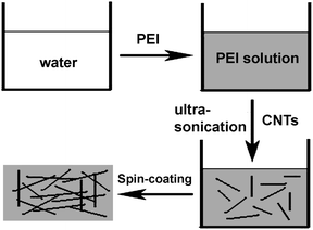 |
| | Scheme 1 Schematic illustration of the fabrication process of the CNT composite films. | |
Experimental
Long carbon nanotube arrays were synthesized on Si wafers at 750 °C, where pure ethylene was used as the carbon source. Forming gas (Ar + H2 = 94% + 6%) was used to carry the carbon source. The flow rates were controlled at 200 sccm for both ethylene and forming gas. The catalysts used in this study were Fe (0.5 nm) on Al2O3 (10 nm) on SiO2 (1 μm)/Si wafers. The Fe and Al2O3 films were deposited by sputtering and ion-beam-assisted deposition, respectively.
Carbon nanotube array were peeled off the substrates and ultrasonicated in nitric acid (40 vol%) for 30 min to remove the catalysts and impurities. The nitric acid solution containing the dispersed carbon nanotubes was then left overnight. Finally, removing the precipitate of amorphous carbon, the upper suspended carbon nanotube solution was collected. The solution was filtered and washed using deionized water several times. In this way, pure carbon nanotubes were obtained.
In a specific example, 10 g PEI was dissolved in 100 g deionized water to form a homogeneous solution. Purified carbon nanotubes were gradually dispersed in PEI solution with the assistance of ultrasonication for 3 h. Different carbon nanotube loaded homogeneous solutions having concentrations of 0.01, 0.02, 0.05, 0.5, 1, and 3 wt% CNTs were prepared to study the effect of CNT loading on the conductivity of the composite films.
Formation of PEI–CNT composite films by spin-coating
Homogeneous PEI–CNT solutions were spun-coated onto glass substrate at 1500 rpm for 15 s. Solid PEI–CNT composite films were obtained after evaporation of water by heating the precursor films on a hot plate at 70 °C for 1 h. Film thickness was controlled by the surrounding height. Here, the thickness of films was ∼0.5 mm.
Characterization
The morphology of the composite films was analyzed by scanning electron microscopy (SEM). The FTIR patterns of the samples were obtained using a Nicolet FTIR spectrometer The electrical conductivity of the films was evaluated using a standard four-probe method using a Physical Property Measurement System (PPMS).
Results and discussion
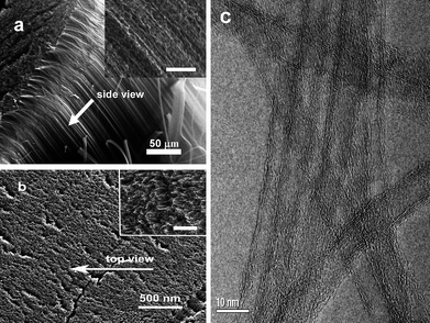
Fig. 1 shows the a CNT array synthesized by chemical vapor deposition. From the cross-sectional scanning electron microscopy (SEM) images (Fig. 1a, and b), the length of CNTs are estimated to be 0.5 mm. The side- and top-views show the CNT array is clean. There are no visible carbon or other particles on the array in the enlarged views from the side and top of the CNT array. The high-resolution transmission electron microscopy (HRTEM) image in Fig. 1c shows the multiwall character of the CNTs with a diameter of ∼8 nm. For CNT dispersion, water-soluble PEI was selected as the medium. Fig. 2 shows CNTs dispersed in water and a PEI solution, respectively. Unlike the CNTs in water (Fig. 2a), the CNTs are dispersed very well in the PEI solution (Fig. 2b). Importantly, the CNTs are dispersed homogeneously. Furthermore, the solution is stable (for at least 15 days) without any noticeable change in color or precipitation. It is worthwhile to note that purification of CNTs is necessary before CNTs are dispersed in PEI solution. Once the CNTs are well-dispersed in PEI solution, the composite films can be easily obtained using a spin-coating technique. Fig. 3 shows the surface morphologies of the PEI–CNT composite films. As can be seen from Fig. 3a, the composite film is very uniform. The enlarged image in Fig. 3b exhibits the high loading of CNTs in the composite films, and that the CNTs tightly combine with each other with the assistance of PEI.
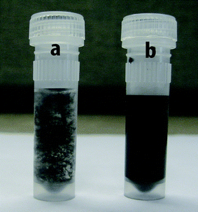 |
| | Fig. 2 Long CNTs dispersed in a) water and b) PEI solution. | |
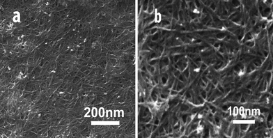 |
| | Fig. 3 SEM images of the PEI–CNT composite films at different magnifications. | |
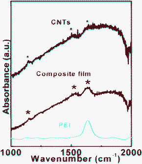
Infrared spectroscopy was used to characterize the PEI–CNT composite films. Fig. 4 shows the absorbance spectrum of the pure CNT, pure PEI, and composite PEI–CNT films, respectively. Three peaks for pure CNTs at 1152, 1530, and 1640 cm−1 (marked by black asterisks) can be assigned to the disorder-induced D-band, the G-band, and a shoulder's D′-band, respectively. The peaks appear a little weak due to strong background from the measuring environment. The pure PEI shows a typical peak at 1640 cm−1.34,35 The spectra for the composite film had the features (marked by red asterisks) obtained from CNTs and PEI, which indicates the obvious presence of both constituents in the composite film.
To test the recycling performance of the CNT composite films, we peeled off the film from the glass substrate, dissolved it in water, and spun-coated it back onto the substrate to form the CNT composite films again. The results show the prepared CNT composite films are reversibly soluble in water. Fig. 5 presents the reversible process: a) PEI–CNT solution, b) the PEI–CNT composite film, and c) ultrasonicating the film in water to form the solution. All the processes between solution and film are easily realized through only ultrasonication in water and spin-coating onto the substrate. The re-obtained solution and composite films are almost the same as the fresh precursor solution and the first CNT composite film. This whole process suggests that the composite films have a good water-soluble properties and can be recycled. Moreover, many synthesis methods for CNT composite films use either high-temperature procedures or organic solvents,15–25 whereas our process requires only benign water as the solvent, and a general low-cost spin-coating approach.
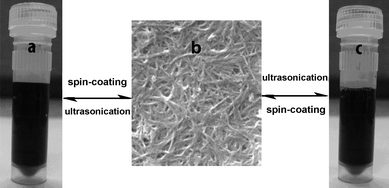 |
| | Fig. 5 The reversible water-soluble performance of the composite films. | |
Fig. 6 shows the conductivity of composite films as a function of loading concentrations of CNTs. It is found that the concentration of CNTs has a significant effect on the conductivity of the composite films. The conductivities are 0.01, 0.21, 31.12, and 43.73 S cm−1 when the concentration of CNTs is 0.05, 0.5, 1, and 3 wt%, respectively. Although PEI shows insulating characteristics, the conductivity of the composite films increases rapidly to 0.01 S cm−1 with a small amount of CNT inclusion (∼0.05 wt%). It should be noted that this level of electrical conduction can meet the requirement of 10−5 Ω cm−2 electrostatic dissipation applications.36,37 Several orders of magnitude enhancement in electrical conductivity has also been reported with a small loading of CNTs (0.0021 wt%).38 In comparison with the conductivities of other composite films with low loading of CNTs,38–40 the present composite films show higher conductivities. We believe that the large aspect ratio and the nanoscale dimensions of the nanotubes play very important roles in enhancing the electrical conductivity of the CNT composite films with low loading of CNTs. In the CNT composites with low loading concentration of CNTs, Bai et al. reported orders of magnitude enhancement of conductivity when the CNTs' length was increased from 1 to 50μm.41 In our case, the length of CNTs, on average, is about 0.5 mm. In addition, well-dispersed nanotubes have higher effective aspect ratios than those of nanotube aggregates. Both the large aspect ratio of long CNTs and the good dispersion of CNTs in the polymer have key effects on the conductivity of composites with low concentration of CNTs.
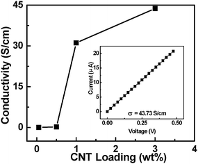 |
| | Fig. 6 The conductivity of the PEI–CNT composite films as a function of loading concentration of CNTs; the inset presents the current vs. voltage characteristic of a PEI–CNT composite film with 3 wt% CNT loading. | |
We note that the conductivity of the CNT composite film is still lower than the axial conductivity of ∼10![[hair space]](https://www.rsc.org/images/entities/char_200a.gif) 000 S cm−1 for CNT ropes.42 In general, the conductivity of films or networks derived from CNTs is 1–2 orders of magnitude lower than that of axial ropes of CNTs.43 It is believed that the conductivity of the CNT composite films in the present work is dominated by percolation processes. We know that PEI is an insulating polymer (the conductivity less than 1 × 10⁻¹⁰ S cm−1). When the CNT is loaded into the PEI matrix, there is not that big a change until the concentration of CNTs is up to 0.02 wt%. There is a dramatic increase in conductivity by eight orders of magnitude when the loading of CNT is over 0.02 wt%. With further loading of CNTs, the conductivity can reach to be ∼43 S cm−1. This behavior is indicative of percolative character in composite systems. The percolation threshold is about 0.02 wt%. It is lower than the 8.4 wt% for the composite films from CNT loading in poly (p-phenlyenevinylene-co-2,5-dioctoxy-m-phenylenylenevinylene)44 but higher than 0.0025 wt% for aligned CNT–epoxy composites.45 Usually, the percolation threshold of electrical conductivity in CNT–polymer composites is influenced by several factors (such as: alignment, aspect ratio, dispersion, etc.).36,46 Additionally, the change of CNT network structure in PEI with the increasing CNT concentration can be schematically described (Scheme 2). As the CNT network becomes highly compact, the effective contact area between the CNTs tends to saturate. Further increase of CNT concentration does not change the conductivity significantly. The highest conductivity of the CNT composite films is 43.73 S cm−1 at a CNT concentration of 3% (inset to Fig. 6). We believe that further improvement in the conductivity of the films can be obtained by using purer, more uniform, more compact and aligned CNTs in the solution.
000 S cm−1 for CNT ropes.42 In general, the conductivity of films or networks derived from CNTs is 1–2 orders of magnitude lower than that of axial ropes of CNTs.43 It is believed that the conductivity of the CNT composite films in the present work is dominated by percolation processes. We know that PEI is an insulating polymer (the conductivity less than 1 × 10⁻¹⁰ S cm−1). When the CNT is loaded into the PEI matrix, there is not that big a change until the concentration of CNTs is up to 0.02 wt%. There is a dramatic increase in conductivity by eight orders of magnitude when the loading of CNT is over 0.02 wt%. With further loading of CNTs, the conductivity can reach to be ∼43 S cm−1. This behavior is indicative of percolative character in composite systems. The percolation threshold is about 0.02 wt%. It is lower than the 8.4 wt% for the composite films from CNT loading in poly (p-phenlyenevinylene-co-2,5-dioctoxy-m-phenylenylenevinylene)44 but higher than 0.0025 wt% for aligned CNT–epoxy composites.45 Usually, the percolation threshold of electrical conductivity in CNT–polymer composites is influenced by several factors (such as: alignment, aspect ratio, dispersion, etc.).36,46 Additionally, the change of CNT network structure in PEI with the increasing CNT concentration can be schematically described (Scheme 2). As the CNT network becomes highly compact, the effective contact area between the CNTs tends to saturate. Further increase of CNT concentration does not change the conductivity significantly. The highest conductivity of the CNT composite films is 43.73 S cm−1 at a CNT concentration of 3% (inset to Fig. 6). We believe that further improvement in the conductivity of the films can be obtained by using purer, more uniform, more compact and aligned CNTs in the solution.
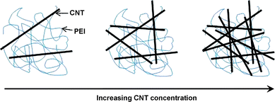 |
| | Scheme 2 The dispersion state of long CNTs in PEI as a function of CNT concentration. | |
The above microscopic view of the conductivity is also supported by the temperature-dependent conductivity of the CNT composite films shown in Fig. 7. The conductivity of the PEI–CNT films increases with temperature from 120 to 300 K (Fig. 7a). This increase suggests semiconducting behavior. In general, a variable range hopping mechanism47 is used to describe temperature-dependent conductivity. In detail, the relationship between conductivity and temperature in Mott's hopping model can be expressed as σ ∞ exp![[hair space]](https://www.rsc.org/images/entities/char_200a.gif) (− A/T
(− A/T![[hair space]](https://www.rsc.org/images/entities/char_200a.gif) 1/(d+1)), where σ is the conductivity, A is a constant, T is the temperature, and d is the dimensionality.48 The plot shown in Fig. 7b can be well described by lnσvs. T−1/4 (d = 3). Its linear fitting coefficient is 0.948. When d = 2 and 1, the linear fitting coefficients are 0.939 and 0.925, respectively. This result suggests that the electron transport is consistent with a three-dimensional hopping mechanism. This behavior is most likely due to the defective structures of CNT composites, in which electrons cannot be confined in the one-dimensional channel along the CNT direction. Instead, electrons hop from one localized site to another, or possibly from one CNT to another.
1/(d+1)), where σ is the conductivity, A is a constant, T is the temperature, and d is the dimensionality.48 The plot shown in Fig. 7b can be well described by lnσvs. T−1/4 (d = 3). Its linear fitting coefficient is 0.948. When d = 2 and 1, the linear fitting coefficients are 0.939 and 0.925, respectively. This result suggests that the electron transport is consistent with a three-dimensional hopping mechanism. This behavior is most likely due to the defective structures of CNT composites, in which electrons cannot be confined in the one-dimensional channel along the CNT direction. Instead, electrons hop from one localized site to another, or possibly from one CNT to another.
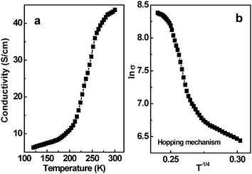 |
| | Fig. 7 a) Temperature-dependent conductivity of the PEI–CNT composite films measured by a four-probe method; b) Scaling of the conductivity (lnσvs. T−1/4) of the PEI–CNT composite films with variable range hopping. | |
Conclusions
In summary, recyclable and electrically conductive CNT composite films have been prepared in a water-soluble PEI matrix by a spin-coating process. Water-solubility tests showed the good recycling performance of the CNT composite films. Due to long CNTs and high CNT loading in PEI, the CNT composite films exhibit excellent electrical conductivity. The conductivity of the composite films is steadily improved as the concentration of CNTs increases, and the conductivity of the composites tends to saturate as the CNT network becomes increasingly compact. The highest conductivity of the PEI–CNT films is around 43.73 S cm−1 at a CNT concentration of 3 wt%.
Acknowledgements
This work was supported by the U.S. Department of Energy through the LANL/LDRD program.
References
- A. Carrillo, J. A. Swartz, J. M. Gamba, R. S. Kane, N. Chakrapani, B. Wei and P. M. Ajayan, Nano Lett., 2003, 3, 1437 CrossRef CAS.
- A. B. Dalton, H. J. Byrne, J. N. Coleman, S. Curran, A. P. Davey, B. McCarthy and W. Blau, Synth. Met., 1999, 102, 1176 CrossRef CAS.
- M. Álvaro, P. Atienzar, J. L. Bourdelande and H. Garcia, Chem. Commun., 2002, 3004 RSC.
- H. Ago, T. Kugler, F. Cacialli, K. Petritsch, R. H. Friend, W. R. Salaneck, Y. Ono, T. Yamabe and K. Tanaka, Synth. Met., 1999, 103, 2494 CrossRef CAS.
- R. Martel, T. Schmidt, H. R. Shea, T. Hertel and P. Avouris, Appl. Phys. Lett., 1998, 73, 2447 CrossRef CAS.
- P. M. Ajayan, Chem. Rev., 1999, 99, 1787 CrossRef CAS.
- S. J. Tans, M. H. Devoret, H. Dal, A. Thess, R. E. Smalley, L. J. Geerligs and C. Dekker, Nature, 1997, 386, 474 CrossRef CAS.
- L. C. Venema, J. W. G. Wildoer, J. W. Janssen, S. J. Tans, H. L. J. T. Tuinstra, L. P. Kouwenhoven and C. Dekker, Science, 1999, 283, 52 CrossRef CAS.
- Z. Xu, Y. Wu, B. Hu, I. N. Ivanov and D. B. Geohegan, Appl. Phys. Lett., 2005, 87, 263118 CrossRef.
- S. Kazaoui, N. Minami, B. Nalini, Y. Kim, N. Takada and K. Hara, Appl. Phys. Lett., 2005, 87, 211914 CrossRef.
- J. Kim, M. Kim and J. Choi, Synth. Met., 2003, 139, 565 CrossRef CAS.
- Y. Ha, E. You, B. Kim and J. Choi, Synth. Met., 2005, 153, 205 CrossRef CAS.
- P. Fournet, J. N. Coleman, B. Lahr, A. Drury, W. J. Blau, D. F. O'Brien and H. H. Horhold, J. Appl. Phys., 2001, 90, 969 CrossRef CAS.
- P. Fournet, D. F. O'Brien, J. N. Coleman, H. H. Horhold and W. J. Blau, Synth. Met., 2001, 121, 1683 CrossRef CAS.
- Z. C. Wu, Z. H. Chen, X. Du, J. M. Logan, J. Sippel, M. Nikolou, K. Kamaras, J. R. Reynolds, D. B. Tanner, A. F. Hebard and A. G. Rinzler, Science, 2004, 305, 1273 CrossRef CAS.
- X. F. Zhang, T. Liu, T. V. Sreekumar, S. Kumar, V. C. Moore, R. H. Hauge and R. E. Smalley, Nano Lett., 2003, 3, 1285 CrossRef CAS.
- H. J. Barraza, F. Pompeo, E. A. O'Rear and E. Resasco, Nano Lett., 2002, 2, 797 CrossRef CAS.
- F. M. Du, R. C. Scogna, W. Zhou, S. Brand, J. E. Fischer and K. I. Winey, Macromolecules, 2004, 37, 9048 CrossRef CAS.
- W. R. Small and M. Panhuis, Small, 2007, 3, 1500 CrossRef.
- D. Qian, E. C. Dickey, R. Andrews and T. Rantell, Appl. Phys. Lett., 2000, 76, 2868 CrossRef CAS.
- M. S. P. Shaffer and A. H. Windle, Adv. Mater., 1999, 11, 937 CrossRef CAS.
- L. Jin, C. Bower and O. Zhou, Appl. Phys. Lett., 1998, 73, 1197 CrossRef CAS.
- C. Bower, R. Rosen, L. Jin, J. Han and O. Zhou, Appl. Phys. Lett., 1999, 74, 3317 CrossRef CAS.
- B. McCarthy, J. N. Coleman, R. Czerw, A. B. Dalton, M. Panhius, A. Maiti, A. Drury, P. Bernier, J. B. Nagy, B. Lahr, H. J. Byrne, D. L. Carroll and W. J. Blau, J. Phys. Chem. B, 2002, 106, 2210 CrossRef CAS.
- X. G. Gong, J. Liu, S. Baskaran, R. D. Voise and J. S. Young, Chem. Mater., 2000, 12, 1049 CrossRef CAS.
- C. A. Poland, R. Duffin, I. Kinloch, A. Maynard, W. A. H. Wallace, A. Seaton, V. Stone, S. Brown, W. MacNee and K. Donaldson, Nat. Nanotechnol., 2008, 3, 423 CrossRef CAS.
- A. Takagi, A. Hirose, T. Nishimura, N. Fukumori, A. Ogata, A. Ohashi, S. Kitajima and J. Kanno, J. Toxicol. Sci., 2008, 33, 105 Search PubMed.
- K. Kostarelos, Nat. Biotechnol., 2008, 26, 774 CrossRef CAS.
-
USPTO Application #: 20090191458, Inventors: Subramanya Herle; Assignee: Matsushita Electric Industrial Co., Ltd. (Osaka, JP).
-
USPTO Application #: 20090168301, Inventors: Sriram Viswanathan, Toshio Tokune; Agent: Capitol City Techlaw, PLLC - Alexandria, VA, US.
- Q. Jia, T. McCleskey, A. Burrell, Y. Lin, G. Collis, H. Wang, A. Li and S. Foltyn, Nat. Mater., 2004, 3, 529 CrossRef CAS.
- G. Zou, M. Jain, H. Zhou, H. Luo, S. Baily, L. Civale, E. Bauer, T. McCleskey, A. Burrell and Q. Jia, Chem. Commun., 2008, 6022 RSC.
- H. Luo, H. Wang, Z. Bi, G. Zou, T. McCleskey, A. Burrell, E. Bauer, M. Hawley, Y. Wang and Q. Jia, Angew. Chem., Int. Ed., 2009, 48, 1490 CrossRef CAS.
- N. Jia, Q. Lian, H. Shen, C. Wang, X. Li and Z. Yang, Nano Lett., 2007, 7, 2976 CrossRef CAS.
- G. Zou, H. Yang, M. Jain, H. Zhou, D. Williams, M. Zhou, T. McCleskey, A. Burrell and Q. Jia, Carbon, 2009, 47, 933 CrossRef CAS.
- M. Moniruzzaman and K. I. Winey, Macromolecules, 2006, 39, 5194 CrossRef CAS.
- R. H. Baughman, A. A. Zakhidov and W. A. de Heer, Science, 2002, 297, 787 CrossRef CAS.
- C. A. Martin, J. K. W. Sandler, M. S. P. Shaffer, M. K. Schwarz, W. Bauhofer, K. Schulte and A. H. Windle, Compos. Sci. Technol., 2004, 64, 2309 CrossRef CAS.
- M. B. Bryning, M. F. Islam, J. M. Kikkawa and A. G. Yodh, Adv. Mater., 2005, 17, 1186 CrossRef CAS.
- S. Barrau, P. Demont, E. Perez, A. Peigney, C. Laurent and C. Lacabanne, Macromolecules, 2003, 36, 9678 CrossRef CAS.
- J. B. Bai and A. Allaoui, Composites, Part A, 2003, 34, 689 CrossRef.
- J. E. Fischer, H. Dai, A. Thess, R. Lee, N. M. Hanjani, D. L. Dehaas and R. E. Smalley, Phys. Rev. B: Condens. Matter, 1997, 55, R4921 CrossRef CAS.
- W. Ma, L. Song, R. Yang, T. Zhang, Y. Zhao, L. Sun, Y. Ren, D. Liu, L. Liu, J. Shen, Z. Zhang, Y. Xiang, W. Zhou and S. Xie, Nano Lett., 2007, 7, 2307 CrossRef CAS.
- J. N. Coleman, S. Curran, A. B. Dalton, A. P. Davey, B. McCarthy, W. Blau and R. C. Barklie, Phys. Rev. B: Condens. Matter Mater. Phys., 1998, 58, R7492 CrossRef CAS.
- J. K. W. Sandler, J. E. Kirk, I. A. Kinloch, M. S. P. Shaffer and A. H. Windle, Polymer, 2003, 44, 5893 CrossRef CAS.
- Y. Z. Long, Z. J. Chen, X. T. Zhang, J. Zhang and Z. F. Liu, J. Phys. D: Appl. Phys., 2004, 37, 1965 CrossRef CAS.
- S. Banerjee and D. Chakravorty, J. Appl. Phys., 1998, 84, 1149 CrossRef CAS.
-
S. N. Mott, Conduction in non-crystalline materials, Clarendon Press, Oxford 1987 Search PubMed.
Footnote |
| † Present address: School of Physical Science and Technology, Soochow University, Suzhou 215006, China |
|
| This journal is © The Royal Society of Chemistry 2010 |
Click here to see how this site uses Cookies. View our privacy policy here. 




![[hair space]](https://www.rsc.org/images/entities/char_200a.gif) 000 S cm−1 for CNT ropes.42 In general, the conductivity of films or networks derived from CNTs is 1–2 orders of magnitude lower than that of axial ropes of CNTs.43 It is believed that the conductivity of the CNT composite films in the present work is dominated by percolation processes. We know that PEI is an insulating polymer (the conductivity less than 1 × 10⁻¹⁰ S cm−1). When the CNT is loaded into the PEI matrix, there is not that big a change until the concentration of CNTs is up to 0.02 wt%. There is a dramatic increase in conductivity by eight orders of magnitude when the loading of CNT is over 0.02 wt%. With further loading of CNTs, the conductivity can reach to be ∼43 S cm−1. This behavior is indicative of percolative character in composite systems. The percolation threshold is about 0.02 wt%. It is lower than the 8.4 wt% for the composite films from CNT loading in poly (p-phenlyenevinylene-co-2,5-dioctoxy-m-phenylenylenevinylene)44 but higher than 0.0025 wt% for aligned CNT–epoxy composites.45 Usually, the percolation threshold of electrical conductivity in CNT–polymer composites is influenced by several factors (such as: alignment, aspect ratio, dispersion, etc.).36,46 Additionally, the change of CNT network structure in PEI with the increasing CNT concentration can be schematically described (Scheme 2). As the CNT network becomes highly compact, the effective contact area between the CNTs tends to saturate. Further increase of CNT concentration does not change the conductivity significantly. The highest conductivity of the CNT composite films is 43.73 S cm−1 at a CNT concentration of 3% (inset to Fig. 6). We believe that further improvement in the conductivity of the films can be obtained by using purer, more uniform, more compact and aligned CNTs in the solution.
000 S cm−1 for CNT ropes.42 In general, the conductivity of films or networks derived from CNTs is 1–2 orders of magnitude lower than that of axial ropes of CNTs.43 It is believed that the conductivity of the CNT composite films in the present work is dominated by percolation processes. We know that PEI is an insulating polymer (the conductivity less than 1 × 10⁻¹⁰ S cm−1). When the CNT is loaded into the PEI matrix, there is not that big a change until the concentration of CNTs is up to 0.02 wt%. There is a dramatic increase in conductivity by eight orders of magnitude when the loading of CNT is over 0.02 wt%. With further loading of CNTs, the conductivity can reach to be ∼43 S cm−1. This behavior is indicative of percolative character in composite systems. The percolation threshold is about 0.02 wt%. It is lower than the 8.4 wt% for the composite films from CNT loading in poly (p-phenlyenevinylene-co-2,5-dioctoxy-m-phenylenylenevinylene)44 but higher than 0.0025 wt% for aligned CNT–epoxy composites.45 Usually, the percolation threshold of electrical conductivity in CNT–polymer composites is influenced by several factors (such as: alignment, aspect ratio, dispersion, etc.).36,46 Additionally, the change of CNT network structure in PEI with the increasing CNT concentration can be schematically described (Scheme 2). As the CNT network becomes highly compact, the effective contact area between the CNTs tends to saturate. Further increase of CNT concentration does not change the conductivity significantly. The highest conductivity of the CNT composite films is 43.73 S cm−1 at a CNT concentration of 3% (inset to Fig. 6). We believe that further improvement in the conductivity of the films can be obtained by using purer, more uniform, more compact and aligned CNTs in the solution.
![[hair space]](https://www.rsc.org/images/entities/char_200a.gif) (− A/T
(− A/T![[hair space]](https://www.rsc.org/images/entities/char_200a.gif) 1/(d+1)), where σ is the conductivity, A is a constant, T is the temperature, and d is the dimensionality.48 The plot shown in Fig. 7b can be well described by lnσvs. T−1/4 (d = 3). Its linear fitting coefficient is 0.948. When d = 2 and 1, the linear fitting coefficients are 0.939 and 0.925, respectively. This result suggests that the electron transport is consistent with a three-dimensional hopping mechanism. This behavior is most likely due to the defective structures of CNT composites, in which electrons cannot be confined in the one-dimensional channel along the CNT direction. Instead, electrons hop from one localized site to another, or possibly from one CNT to another.
1/(d+1)), where σ is the conductivity, A is a constant, T is the temperature, and d is the dimensionality.48 The plot shown in Fig. 7b can be well described by lnσvs. T−1/4 (d = 3). Its linear fitting coefficient is 0.948. When d = 2 and 1, the linear fitting coefficients are 0.939 and 0.925, respectively. This result suggests that the electron transport is consistent with a three-dimensional hopping mechanism. This behavior is most likely due to the defective structures of CNT composites, in which electrons cannot be confined in the one-dimensional channel along the CNT direction. Instead, electrons hop from one localized site to another, or possibly from one CNT to another.
