Electrospun nanofibers for neural tissue engineering
Jingwei
Xie
,
Matthew R.
MacEwan
,
Andrea G.
Schwartz
and
Younan
Xia
*
Department of Biomedical Engineering, Washington University, St. Louis, MO 63130, USA. E-mail: xia@biomed.wustl.edu
First published on 27th October 2009
Abstract
Biodegradable nanofibers produced by electrospinning represent a new class of promising scaffolds to support nerve regeneration. We begin with a brief discussion on the electrospinning of nanofibers and methods for controlling the structure, porosity, and alignment of the electrospun nanofibers. The methods include control of the nanoscale morphology and microscale alignment of the nanofibers, as well as the fabrication of macroscale, three-dimensional tubular structures. We then highlight recent studies that utilize electrospun nanofibers to manipulate biological processes relevant to nervous tissue regeneration, including stem cell differentiation, guidance of neurite extension, and peripheral nerve injury treatments. The main objective of this feature article is to provide valuable insights into methods for investigating the mechanisms of neurite growth on novel nanofibrous scaffolds and optimization of the nanofiber scaffolds and conduits for repairing peripheral nerve injuries.
 Jingwei Xie Jingwei Xie | Jingwei Xie received his BSc and MSc degrees (with Professor. Xiaohua Lu) from Nanjing University of Technology in 1999 and 2002, respectively. He received his PhD degree (with Professor Chi-Hwa Wang) from the Department of Chemical and Biomolecular Engineering, National University of Singapore in June 2007, and immediately joined Professor Younan Xia’s group as a postdoctoral research associate at Washington University in St. Louis, where his research centers on the fabrication of nanostructured materials for biomedical applications. His research interests include micro- and nanofabrication, neural tissue engineering, stem cell therapy, tendon repair, and controlled release formulations. |
 Younan Xia Younan Xia | Younan Xia received his BSc degree in chemical physics from the University of Science and Technology of China in 1987. He received a MSc degree in inorganic chemistry from the University of Pennsylvania (with the late Professor Alan G. MacDiarmid) in 1993 and a PhD degree in physical chemistry from Harvard University (with Professor George M. Whitesides) in 1996. Currently, he is the James M. McKelvey Professor for Advanced Materials in the Department of Biomedical Engineering, Washington University in St. Louis. His research centers on the design and synthesis of nanostructured materials for applications in tissue engineering, drug delivery, cancer treatment, imaging, sensing, catalysis, energy conversion, photonics, and electronics. |
1. Introduction
Peripheral nerve injuries often result from acute trauma and may lead to chronic sensorimotor defects due to the lack of a successful and robust reparative technique.1 Clinically, the typical procedures for repairing injured peripheral nerves are based upon either direct coaptation of the transected nerve stumps (in the case of small nerve defects) or the use of nerve grafts (in the case of large nerve defects).2 For autografting that involves the harvest of a donor nerve from the patient and transplantation into the defect site, it can often yield superior functional recovery. The procedure, however, tends to be impaired by a number of drawbacks such as loss of function at the donor site, limited availability of donor nerves, size mismatch between the donor and recipient nerves, and the need for multiple surgeries.3 As an alternative, allografts (i.e., nerves harvested from other human being or animal) can be employed, but patients are at a risk of immuno- and disease-related complications. As a result, there exists an imperative need for the development of artificial nerve guidance conduits (NGCs), which can potentially overcome the limitations associated with nerve autografts and allografts.Many types of NGCs have been developed to facilitate axonal guidance and thus to enhance nerve regeneration; good examples include arrays of microchannels and microfilaments, fiber bundles, hollow fiber membranes, and multi-layered tubes.4 These synthetic NGCs offer a range of advantages over nerve autografts and allografts, including improved availability, a wider range of size selection, no extra surgery to harvest the donor nerve, reduced axonal escape at the suture site, and the ability to stimulate and guide regenerating axons.5 While most of these synthetic conduits have shown great promise in vitro, they are still challenged or limited by the inability to direct and enhance axonal regeneration in vivo.6 In addition, synthetic NGCs are currently limited in supporting functional nerve regeneration across nerve defects beyond a critical length.6a In general, NGCs are incapable of selectively guiding motor and sensory axons toward the appropriate end organs. Thus, only a limited percentage of the regenerated fibers is able to re-innervate the desired motor or sensory targets. Most of the fabricated conduits to date are also troubled by a rigid structure with limited flexibility, which may impair intraoperative handling and make it very difficult to implant the devices.7 To this end, a new class of NGCs based upon electrospun nanofibers may have the potential to overcome some of the limitations associated with traditional NGCs.
Owing to the small feature size, a nonwoven mat derived from electrospun nanofibers typically exhibits a high porosity and large surface area. These features enable a nanofiber-based scaffold to closely mimic the hierarchical structure of the extracellular matrix (ECM), an environment critical for cell attachment/migration, signal transduction, and nutrient transport.8aNanofibers can also be functionalized via encapsulation or attachment of bioactive molecules such as native ECMproteins and nucleic acids to potentially guide both the differentiation and proliferation of cells seeded on the scaffold. In addition, electrospun nanofibers can be readily aligned into uniaxial arrays. The resulting anisotropic material properties have been shown to be an effective cue to direct and enhance neurite outgrowth, providing a major advantage over other isotropic materials such as hydrogels or nonwoven fibrous structures. By manipulating their morphology, alignment, stacking, and/or folding, the electrospun nanofibers can be assembled into a large number of hierarchically structured scaffolds or conduits. All these attributes make electrospun nanofibers an intriguing class of materials for neural tissue engineering.8
This feature article reviews the recent progress on the application of electrospun nanofibers to neural tissue engineering. We illustrate how to control the alignment and morphology of electrospun nanofibers and to fabricate novel NGCs from nanofibers. A major emphasis is placed on highlighting the potential of electrospun nanofibers for manipulating stem cell differentiation, guiding and promoting neurite outgrowth, and ultimately serving as NGCs for peripheral nerve injury repair.
2. Electrospinning of nanofibers
Electrospinning is a remarkably simple and versatile technique and it has been successfully applied to more than 100 different types of polymers derived from both natural and synthetic origins.9Fig. 1 shows a typical apparatus for electrospinning, which consists of three major components: a high-voltage power supply, a spinneret, and an electrically conductive collector. An ordinary hypodermic needle and a piece of aluminium foil serve well as the spinneret and collector, respectively. The polymer to be electrospun may be in the form of a solution or melt that is typically loaded in a syringe and fed into the spinneret at a specific rate by controlling with a syringe pump. In some cases, a well-controlled environment (e.g., with suitable humidity, temperature, and atmosphere) may also be required for electrospinning, especially for the fabrication of composite or ceramic nanofibers from a sol –gel precursor.10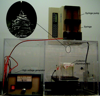 | ||
| Fig. 1 A typical setup for electrospinning which consists of three major components: a high-voltage supply, a spinneret (in this case, a flat-end needle), and a collector (in this case, a piece of aluminium foil). The inset shows a typical photograph of an electrospinning jet captured using a high-speed camera. Adapted with permission from refs. 8a and 12. Copyright Wiley-VCH (2008) and Elsevier (2008). | ||
The essence of electrospinning is to generate a continuous jet by charging the surface of a liquid droplet. In contrast to the simplicity of setup, the mechanism of electrospinning is much more complicated. As established in a recent study, the small diameter of electrospun fibers is a result of the whipping motion that exerts a strong axial force, rather than the splaying of jet, as previously believed.11 The inset in Fig. 1 shows a snapshot of a jet, which was captured with the aid of a high-speed camera.12 The whipping instability is thought to originate mainly from the electrostatic interactions between the external electric field and the charges immobilized on the surface of the jet. The solution for electrospinning has to possess appropriate viscoelastic properties in order to survive the whipping process that tends to break the jet into individual droplets. As a result of continuous acceleration and stretching of the jet, electrospun nanofibers are typically several orders of magnitude thinner than those produced using conventional spinning techniques. In general, electrospinning is capable of generating fibers as thin as tens of nanometres in diameter by optimizing parameters such as the intrinsic properties of the solution (e.g., polarity and surface tension of the solvent, molecular weight and conformation of the polymer, polymer chain entanglement and intermolecular interactions, viscosity and elasticity, and electrical conductivity of the solution) and the operational parameters including the strength of the electric field, the distance between the spinneret and the collector, and the feeding rate for the solution.9
3. Controlling nanofiber morphology
The morphology of an individual nanofiber can be manipulated by controlling the parameters for electrospinning. Here we limit the discussion to specific examples that could have potential implications in neural tissue engineering. Successful electrospinning of a polymer solution requires rapid evaporation of the solvent while the jet is accelerated toward the collector. This results in evaporative cooling, which significantly reduces the surface temperature of the jet. Such localized cooling at the surface of a jet can result in moisture condensation, leading to vapor-induced phase separation.13 In a typical situation, the moisture in the surrounding air condenses onto the fiber and grows in the form of small droplets as the surface is cooled. The droplets remain as individual entities and behave like solid spheres with respect to convection currents on the surface of the jet. At a later stage, as the jet solidifies through solvent evaporation, the water droplets become voids on the surface of the fibers. Fig. 2A shows SEM image of electrospun poly(lactic acid) (PLA) fibers with a high surface porosity generated via cooling-induced phase separation. Alternatively, uniformly porous electrospun fibers can be fabricated by modifying the collection scheme. For example, Xia et al. have demonstrated the fabrication of highly porous fibers by electrospinning the jet directly into a cryogenic liquid.14 Well-defined pores developed within each fiber as a result of the temperature-induced phase separation between the polymer and the solvent and the evaporation of the solvent under freeze-drying conditions. Fig. 2B shows TEM images of a porous poly(styrene) (PS) fiber prepared using this method, which was porous throughout. This approach has been extended to a number of polymers including poly(vinylidene fluoride) (PVDF), poly(acrylonitrile) (PAN), and poly(ε-caprolactone) (PCL).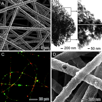 | ||
| Fig. 2 (A) SEM image of poly(lactic acid) fibers with a porous structure fabricated by vapor-induced phase separation. (B) TEM images of polystyrene fibers with a porous structure fabricated by placing the collector in a liquid nitrogen bath. (C) Fluorescence micrograph of polyurethane fibers containing PVA/EGF-AF488 and PVA/BSA-TR particles. (D) SEM image of polypyrrole tubes. Adapted with permission from refs. 8a, 14,15, and 16. Copyright Wiley-VCH (2008), American Chemical Society (2006), and Wiley-VCH (2009). | ||
In addition to the creation of voids in fibers, it is possible to fill distinct domains within each fiber with specific molecules of interest. Fig. 2C shows a fluorescence micrograph of polyurethane (PU) fibers containing an endothelial growth factor fluorescently labeled with Alexafluor 488 (EGF-AF) (green) and bovine serum albumin fluorescently labeled with Texas-Red (BSA-TR) (red). These fibers were fabricated by separately encapsulating each biological species into poly(vinyl alcohol) (PVA) nanoparticles using a single-emulsion method, and then electrospinning a polymer solution containing the PVAnanoparticles.15 Upon electrospinning, Wnek et al.15 obtained polymer fibers containing distinct domains of each biological species. Compared with the uniform distribution of a single component inside an electrospun fiber, the encapsulation of two components in distinct domains offers the opportunity to control the release of multiple compounds at different rates. This capability is of particular interest to the field of neural tissue engineering, where a set of biological cues is often needed for controlling the fate of cells.
Fibers with a core–sheath morphology can be fabricated by either co-axial electrospinning or coating the surface of electrospun nanofibers with a different material post electrospinning. Xia et al. have prepared conductive core–sheath nanofibersvia a combination of electrospinning and aqueous polymerization.16 Specifically, electrospun nanofibers of PCL or PLA were employed as templates to generate uniform sheaths of polypyrrole (PPy)—a conducting polymer—via in situpolymerization. Fig. 2D shows an SEM image of PPynanotubes, which were fabricated by soaking the PCL–PPy core–sheath nanofibers in methylene chloride to selectively remove the PCL cores.
4. Controlling nanofiber alignment
In a typical situation, electrospun nanofibers are deposited on the collector as a nonwoven mat, with no preferential orientation for the fibers (Fig. 3A). It is possible to align the fibers into an uniaxial array by using different types of collectors to manipulate the distribution of the electric field. One of the early methods developed for this purpose employed a rotating mandrel to collect electrospun nanofibers as parallel arrays. In this case, the linear speed of the mandrel must match the speed of the jet (typically 1–5 m s−1) in order for the fibers to be mechanically stretched and aligned around the circumference of the mandrel.17 A lower rotation speed results in less precise fiber alignment while a higher rotation speed can exert a tensile load that may cause the fiber to break. In addition, this technique can only achieve good alignment when the width of the mandrel becomes very thin (typically, below 5 mm), similar to a disc, and the large mechanical forces involved could easily cause the fibers to break during deposition.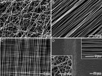 | ||
| Fig. 3 SEM images of different assemblies of electrospun nanofibers: (A) a nonwoven mat of randomly oriented poly(ε-caprolactone)nanofibers, (B) an uniaxially aligned array of poly(ε-caprolactone)nanofibers, (C) a perpendicularly stacked array of poly(ε-caprolactone)nanofibers, and (D) a mat containing both random (left side) and aligned (right side) poly(ε-caprolactone)nanofibers. Adapted with permission from ref. 32. Copyright American Chemical Society (2009). | ||
To overcome these limitations, new types of collectors have been developed to provide a better control over fiber alignment, including a rapidly oscillating frame, a ring electrode, a metal frame, a rotating drum, and a pair of electrodes separated by an insulating gap.18 Among these new approaches, the insulating gap stands out as a particularly simple and scalable method.19 Inclusion of an insulating gap into the collector dramatically alters the distribution of the electric field between the charged spinneret and the grounded collector. Uniaxial alignment of the fiber is achieved as the jet descends into the vicinity of the collector and the charges on the fiber start to induce opposite charges on the conductive regions across the insulating gap. The electrostatic attractions between the opposite charges subsequently stretch and align the fiber across the gap. For a conventional collector, the charges on the deposited fiber are often quickly dissipated into the ground. However, with the introduction of an insulating gap, the charges can remain on the fiber for an extended period of time, generating electrostatic repulsions between the deposited and incoming fibers. This effect further improves the fiber alignment with respect to collection time. Fig. 3B shows an SEM image of an uniaxially aligned array of poly(vinyl pyrrolidone) (PVP) fibers that were collected across two silicon strips separated by an air gap. This simple approach is able to overcome most of the technical problems associated with other alignment techniques. Additionally, the air gap allows one to easily transfer the aligned fibers from the collector onto other solid supports and further stack them into a multi-layered structure. Fig. 3C shows an SEM image of a double-layered structure fabricated by sequentially transferring aligned fibers from the gap region onto a silicon wafer. This method can also be extended by replacing the void gap with a highly insulating substrate such as quartz or PS. By patterning an array of electrodes on the insulating substrate, one can guide the fibers to directly deposit into a multi-layered film by alternating the high-voltage application scheme.20Fig. 3D shows an SEM image of a fiber mat containing both random (left side) and uniaxially aligned (right side) fiber regions achieved by using two metal plates separated by an air gap. In this case, random nanofibers were deposited on the conductive metal substrates while the fibers were uniaxially aligned across the air gap.
5. Fabricating nerve guidance conduits
Macroscale tubes made of electrospun nanofibers are promising candidates for application as vascular grafts and nerve conduits.7,21Fig. 4 illustrates the schematics of several types of such tubular structures. Uniform tubes comprised of random or circumferentially aligned fibers can be readily fabricated by depositing the fibers on a rotating mandrel with a relatively low speed. A second approach is to manually process membranes of aligned or random nanofibers into various three-dimensional (3D) constructs post electrospinning. For example, one can fabricate a tube by rolling up a fiber membrane and securing the edges through the use of a solvent, glue, or heating.22 Significantly, this technique allows one to stack multiple layers, such as a mesh of aligned fibers and a nonwoven mat of random fibers before rolling. The tubes fabricated in this way have a double-layered structure, with random fibers in the outer layer and aligned fibers in the inner layer. In addition, Ramakrishna et al. have demonstrated a method for fabricating a tube consisting of diagonally aligned electrospun fibers through a combination of electrostatic and mechanical approaches.23 The tube was obtained by depositing fibers on a rotating Teflon tube, resulting in a tubular structure with uniform thickness and superior mechanical strength without any lines of weakness. A knife-edged auxiliary electrode, placed at a 45° angle relative to the long axis of the rotating Teflon tube and parallel to the needle, was charged with a polarity opposite to the spinneret, creating an electrostatic field that promoted diagonal fiber alignment on the collector. More recently, Chang and Zhang reported a static method for fabricating 3D tubes composed of ultrafine electrospun fibers.24 By making use of this technique, one can simultaneously prepare arrays of microscale and macroscale tubes with multiple patterns, sizes, shapes, structures, and even interconnected channels.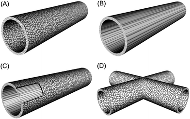 | ||
| Fig. 4 Schematic illustrating various tubular structures composed of: (A) random fibers, (B) aligned fibers, (C) random fibers in the outer layer and aligned fibers in the inner layer, and (D) interconnected tubes composed of random fibers. | ||
6. Electrospun nanofibers for neural tissue engineering
6.1. Manipulating the differentiation of stem cells
Stem cell differentiation is controlled by a complex pattern of gene regulation, which is governed by an array of cellular signaling pathways. In principle, the differentiation of stem cells can be manipulated via biochemical, topographical, and electrical cues.25 Recently, researchers have started to explore the use of nanoscale structures to stimulate and control the differentiation of stem cells. Electrospun nanofibers are emerging as a new platform that can be exploited for understanding, assessing, and manipulating the differentiation of stem cells.Xia et al. reported that embryonic stem cells (ESCs) seeded on nanofibers could be induced to differentiate into neural lineages.26 More significantly, it has been demonstrated that aligned nanofibers could not only enhance the differentiation of ESCs into neural lineages but also control the direction of neurite outgrowth from the seeded cells. Fig. 5 shows fluorescence micrographs of immunostained RW4 embryoid bodies (EBs) taken after 14 days of culture on aligned PCLnanofibers. Specifically, Fig. 5A and B, shows the results of Tuj1 staining, which is limited to cells that display a neuronal phenotype , as evidenced by clear visualization of both the cell bodies and extending axonal protrusions. Fig. 5C and D, shows the results of staining by O4, an antibody that recognizes an oligodendrocyte-specific glycolipid and therefore displays the multipolar morphology characteristic of oligodendrocytes. Fig. 5E and F, shows the results of staining for glial fibrillary acidic protein (GFAP). Cells expressing the astrocytic marker, antigen GFAP, exhibit a flat morphology characteristic of cultured astrocytes. These micrographs also indicate that the neurites were extended along the alignment direction of the nanofibers. The oligodendrocytes also appear to have migrated along the long axis of the aligned nanofibers, indicating possible myelination of the extending axons. In contrast, when a scaffold of random nanofibers was employed, the neurites appeared to extend along all possible directions from the main body of the EB. Also, both oligodendrocytes and astrocytes migrated randomly to the surrounding region of the EBs. Furthermore, more astrocytes were present around the EBs cultured on random fibers than those on aligned fibers.
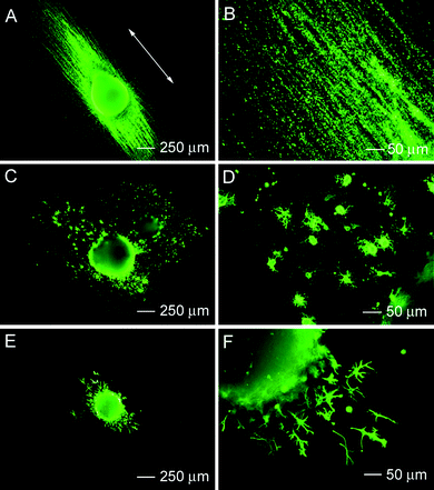 | ||
| Fig. 5 Immunohistochemistry performed for RW4 embryoid bodies after 14 days of culture on aligned poly(ε-caprolactone)nanofibers for mature cell markers including (A, B) Tuj1 (for neurons), (C, D) O4 (for oligodendrocytes), and (E, F) GFAP (for astrocytes). Adapted with permission from ref. 26. Copyright Elsevier (2009). | ||
In another recent study, Mao et al. studied the influence of the diameter of electrospun fibers on the differentiation and proliferation of neural stem cells.27 As the diameter was increased, the neural stem cells showed less migration, spreading, and proliferation in the presence of fibroblast growth factor-2 (FGF-2) and serum-free medium. When cultured in 1 mM retinoic acid and 1% fetal bovine serum (FBS) in a petri dish, the neural stem cells spread and assumed a glial cell shape and preferentially differentiated into oligodendrocytes, whereas on 749-nm and 1452-nm fibers, they were elongated and preferentially differentiated into neuronal lineage. These results suggest that the topographical cue, when applied in conjunction with biochemical signals, may become an instructive tool for regulating the differentiation of stem cells. By imposing different biochemical and topological conditions on the stem cellsvia the scaffold material, it is possible to guide and dictate both the differentiation and proliferation of neural stem cells.
Previous studies indicated that the elasticity of a matrix material could also influence the fate of stem cells and variations in this parameter can direct human mesenchymal stem cells (MSCs) toward neuron, muscle, or bone lineages.25d To this end, engineering the elasticity of electrospun nanofibers could provide a simple and versatile means for controlling the differentiation of stem cells. It has also been reported that immobilization of signaling proteins could enable further control of the fate of stem cells.28 This work suggests that immobilization of signaling proteins such as leukemia inhibitory factor on the surface of electrospun nanofibers could provide another interesting approach to directing the differentiation of stem cells. Furthermore, encapsulation of small molecules such as retinoic acid within electrospun nanofibers can also be used to control the fate of stem cells through a sustained release mechanism.
6.2. Directing and promoting neurite outgrowth
Many studies have demonstrated that microchannels, microgrooves, microridges, and stripes can provide topographical cues to direct neurite extension. However, compared to the dimensions of the ECM, these microstructures are almost on the same scale as the diameter of axons or cells and thus are unable to support the sub-cellular events usually controlled by the ECM. Due to their submicron or even smaller sizes, electrospun nanofibers are supposed to be more physiologically relevant in terms of their potential to mimic the ECM. As an example, the highly anisotropic feature of aligned electrospun nanofibers has been employed to successfully guide the outgrowth of neurites. Ramakrishna et al. found that scaffolds made of aligned nanofibers were better suited for culturing nerve stem cellsin vitro than scaffolds of random microfibers.29 The fluorescence micrographs in Fig. 6A and B, show C17.2 neural stem cells stained with anti-neurofilament 200, which were cultured on both random and aligned electrospun nanofibers. A comparison of these two images clearly indicates that aligned nanofibers can direct neurite extension. Martin et al. also demonstrated that aligned electrospun nanofibers without any surface modification could specify the direction of dorsal root ganglia (DRG) neurite growth and even guide axonal growth and glial cell migration.30 However, most of these studies failed to address the effect of fiber density on directing neurite outgrowth. More recently, by controlling the deposition time to tailor fiber density, Gilbert et al. reported that an increase in fiber density correlated to an increase in the number of neurites, but the average neurite length was not statistically different between the two different fiber densities.31 However, this study only examined a limited range of fiber densities and the fiber's diameter was on the micron scale.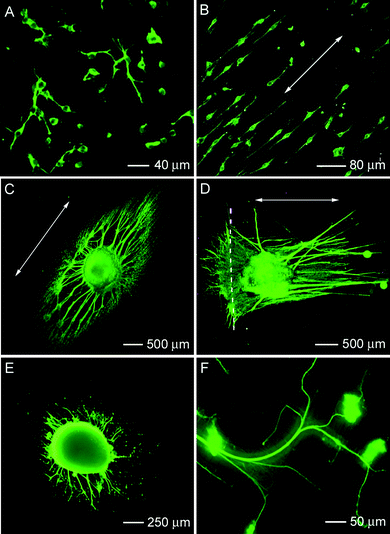 | ||
| Fig. 6 Fluorescence micrographs showing immunostained neurofilament 200 kD in neural stem cells after 2 days of culture: (A) on random nanofibers and (B) on aligned nanofibers. (C) Typical neurite field projected from dorsal root ganglia on aligned poly(ε-caprolactone)nanofibers with laminin coating. (D) Typical neurite field projected from dorsal root ganglia at a border between random and aligned poly(ε-caprolactone)nanofibers with laminin coating. (E, F) Typical neurite field projected from dorsal root ganglia on a mat of perpendicular poly(ε-caprolactone) fibers. Adapted with permission from refs. 29 and 32. Copyright Elsevier (2005) and American Chemical Society (2009). | ||
Most recently, Xia et al. investigated neurite outgrowth on nanofiber scaffolds with different orders, structures, and surface properties.32 The fluorescence micrograph in Fig. 6C shows a typical neurite field extended from DRG cultured on aligned PCLnanofibers whose surface had been coated with laminin. As previously noted, by making use of a collector composed of two metal strips separated by an air gap, it was possible to fabricate scaffolds containing both aligned and random nanofibers. When DRG were seeded at the border separating aligned and random nanofibers, the same DRG simultaneously expressed aligned and random neurite fields in response to the underlying nanofibers (Fig. 6D). When cultured on a double-layered scaffold where the nanofibers in each layer were aligned along directions perpendicular to each other, the neurites were found to be dependent on the fiber's orientation in both layers. The biaxial pattern observed in this study demonstrates that neurite outgrowth can be influenced by nanofibers in different layers of a scaffold, rather than the topmost layer only, in a density dependent manner. At low fiber density (with fiber separation ≈ 5 µm), it was demonstrated for the first time that some of the neurites growing along the long axis of the fibers in one layer suddenly made a sharp turn to follow the long axis of the fibers in the other layer (Fig. 6E and F).
Aligned electrospun nanofibers have been demonstrated to provide guidance for neurite extension. However, guidance of neurite extension alone is insufficient for promoting nerve regeneration. Fast neurite outgrowth plays a critical role as well and can be efficiently enhanced using electrospun nanofibers functionalized with bioactive molecules such as ECMproteins (e.g., laminin and fibronectin), neuroactive peptides (e.g., human tenascin), or growth factors (e.g., basic fibroblastgrowth factor, bFGF, and nerve growth factor, NGF). Typical methods for functionalizing electrospun nanofibers are based on surface conjugation and bulk encapsulation. In some cases, surface treatment can also affect the interaction between the cells and nanofibers. Ramakrishna et al. used a simple plasma treatment procedure to improve the hydrophilicity of electrospun PCLnanofibers, leading to enhancement of adhesion, proliferation, and interactions with the surface of nanofibers for Schwann cells. They further demonstrated that plasma-treated PCLnanofibers could serve as a cost-effective alternative to scaffolds made from a blend of PCL and collagen for peripheral nerve injury repair.33 Li et al. immobilized bFGF and laminin on PLAnanofibers using di-amino-poly(ethylene glycol) and heparin as linker molecules, in an effort to simulate the physical and biochemical properties of native matrix fibrils.34 The immobilized biochemical factors were found to be as effective as soluble factors in synergizing with aligned nanofibers to enhance neurite outgrowth by 2–4 fold. This study highlighted the relative importance of nanoscale topography and chemical signaling in guiding axonal outgrowth. In another study, Meiners et al. reported that surface modification of electrospun nanofibers with neuroactive peptides derived from human tenascin-C significantly enhanced neuronal attachment, neurite generation, and neurite extension in vitro as compared to poly(L-lysine)-coated cover slips.35 Such enhanced performance is presumably due to a combination of the 3D nanofiber architecture and chemical cues that provide a more native-like environment for neuronal growth.
Mey et al. tested the biocompatibility of 25 : 75 collagen/PCL blend nanofibers by assessing cell adhesion, survival, migration and effects on cell morphology, axonal growth and axonal guidance.36 It was shown that Schwann cell migration, neurite orientation, and process formation of Schwann cells, fibroblasts and olfactory ensheathing cells were all improved on collagen/PCL fibers when compared with PCL fibers. While the velocity of neurite elongation from DRG explants was higher on PCL fibers, analysis of isolated sensory neurons showed significantly better axonal guidance by the collagen/PCL blend fibers. This study demonstrated that electrospun fibers composed of a collagen and PCL blend represent a better substrate for supporting cell proliferation, neurite outgrowth, and cell migration and, as such, would be a more suitable material for fabricating artificial nerve implants. In a separate study, Ramakrishna et al. corroborated this result by demonstrating that electrospinning a blend of laminin and a synthetic polymer is a facile and efficient method for the fabrication of a biomimetic scaffold.37 Other than blending laminin with PCL, they also investigated a blend of chitosan and PCL, which showed better tensile strength and better cell attachment and proliferation than either chitosan or PCL scaffolds alone. This result indicates that blend materials are able to take advantage of both the superior mechanical properties of a synthetic polymer, like PCL, and the cytocompatibility of a natural polymer, like chitosan.38 Furthermore, the chitosan/PCL blend nanofibers not only promoted the adhesion of Schwann cells, but also helped to maintain their characteristic cell morphology and cell phenotype , providing a new class of scaffolds for neural tissue engineering.
In addition to incorporating ECMproteins and growth factors, applying an electric field to the nanofiber system represents another way to further enhance neurite outgrowth. A number of recent studies have demonstrated the introduction of electrical cues into electrospun fibers by coating the fiber surface with a conductive polymer.16,39 Xia et al. functionalized electrospun PCLnanofibers by coating them with PPy to form conductive, core–sheath nanofibers.16 These conductive nanofibers offer a unique system for studying the synergistic effect of different cues on neurite outgrowth in vitro. It was found that explanted DRG adhered well to the conductive, core–sheath nanofibers and generated neurites across the surface when the culture medium was supplemented with a NGF. Furthermore, the neurites could be oriented along one direction and their maximum length was enhanced by 82% when they were grown on uniaxially aligned nanofibers as compared with their growth on random nanofibers. Electrical stimulation was found to further increase the maximum length of neurites for random and aligned scaffolds by 83% and 47%, respectively, relative to controls without electrical stimulation. It is worth noting that neurotrophic factors, ECMproteins, and other types of functional molecules can also be incorporated into or onto the surface of the PPy sheath as a means of further enhancing neurite outgrowth. Cells (e.g., neural and embryonic stem cells) could be seeded on the core-sheath nanofibers as well to form artificial nerve tissue grafts. These approaches may represent the next generation of advanced synthetic nerve conduits capable of simultaneously presenting electrical stimulation, topographic cues, and biochemical signals for peripheral nerve injury repair.
Although considerable research has been carried out to characterize the role of electrospun nanofibers in guiding and promoting neurite outgrowth in vitro, much less attention has been paid to the effects of the mechanical properties (e.g., stiffness) and roughness (e.g., surface porosity) of nanofibers, and the role of the substrate on which the nanofibers are deposited. In addition, immobilized concentration gradients of attractive or repellent molecules on the surface of electrospun nanofibers could provide another biologically inspired route to achieve fine control over the direction and enhancement of neurite extension.
6.3. Repairing peripheral nerve injuries
As noted above, a large number of studies have demonstrated the use of electrospun nanofibers in guiding and enhancing neurite extension and axonal regeneration from primary neuronal populations in vitro. The results of these studies strongly suggest that nanofiber-based scaffolds hold a great potential as a new class of synthetic NGCs for repairing peripheral nerve injuries and defects in vivo. Although many types of biomaterials have been examined for constructing NGCs, the use of electrospun nanofibers remains largely unexplored. Initial studies conducted by Ramakrishna et al. demonstrated that 5 out of 11 nanofiber-based NGCs consisting of random poly(lactide-co-glycolide) (PLGA) nanofibers were able to support nerve regeneration across a 10-mm nerve defect upon immunohistochemical and histomorphometric analysis,40 albeit no characterization of functional recovery was provided. Gelain et al. obtained similar results when they used NGCs consisting of random nanofibers to repair a 10-mm defect in a rat sciatic nerve.7 The fibers were electrospun from a polymer blend of PLGA and PCL. These results demonstrate that nanofiber-based scaffolds (without ECMprotein coating or immobilized neurotrophic factor) were able to function as NGCs. Significantly, Gelain et al. demonstrated that the regenerated nerve tissue contained in the nanofiber-based NGCs 16 weeks after implantation was capable of conducting electrical impulses and supporting retrograde transport of fluorescent tracers. Observation of such functional recovery by the regenerative nerve tissue, although incomplete, suggested that nanofiber-based NGCs may not only encourage neurite outgrowth from peripheral nerve tissue in vivo, but that they may also effectively support the reinnervation of distal fiber tracts by regenerating axons. Both Chung and Itoh et al. further examined the use of assemblies of PLGA and poly(p-dioxone) (PPD) nanofibers and chitosan nonwoven microfiber/nanofiber NGCs to promote peripheral nerve regeneration in vivo.41 Nevertheless, none of these studies used aligned electrospun nanofibers to take advantage of their guidance effect on axonal growth. Initial studies on the use of electrospun nanofiber materials as NGCs suggest that these materials are promising for the repair and regeneration of peripheral nerve tissue, although the full potential of such NGCs remains to be determined.For most of the in vivo studies to date, the nanofiber-based NGCs were constructed by collecting a cylindrical tube of random nanofibers using a rotating mandrel. While this method emphasizes the simplicity with which such nanofiber conduits can be fabricated, this technique is not suitable for fabricating NGCs composed of axially aligned nanofibers. Most recently, a few studies have begun to investigate the effect of nanofiber alignment on nerve regeneration. These studies utilized nanofiber-based NGCs constructed by rolling and sealing non-woven nanofiber mats with variations in both fiber organization and composition. Using this fabrication method, Leong et al. demonstrated that NGCs composed of axially aligned fibers were able to improve peripheral nerve regeneration across a 15-mm nerve defect compared with NGCs composed of random or circumferentially aligned fibers.22 This observation confirms that nanofiber alignment is able to influence both the axonal regeneration and the regenerative tissue response in vivo. Additionally, these results also suggest that the immobilization or encapsulation of neurotrophic factors, such as NGF and Glial cell-derived neurotrophic factor (GDNF), in or on nanofiber-based NGCs may provide a simultaneous and synergistic method of enhancing and guiding nerve regeneration in vivo. In another study, Bellamkonda et al. examined the repair of a 17-mm nerve gap using a NGC fabricated by stacking 10–12 layers of axially aligned or random nanofibers within two halves of a longitudinally split polysulfone tube.42 It was demonstrated that the aligned, but not the random fiber, construct successfully promoted regeneration of axons across the 17-mm nerve gap, re-innervated muscles, and formed new neuromuscular junctions, as confirmed by histological, electrophysiological, and behavioral analysis.
While these studies provide new insight into the use of electrospun nanofibers in controlling and enhancing peripheral nerve regeneration, many questions regarding the use of nanofiber-based NGCs remain to be addressed. For example, in the aforementioned cases, the outer layer of the conduits was made of solid film which could limit the diffusion of nutrients into and waste out of the scaffold material. Two of the most important objectives in future investigations of nanofiber-based NGCs as clinically viable devices to promote peripheral nerve regeneration will be: i) to determine whether nanofiber-based NGCs support or enhance functional sensorimotor recovery following peripheral nerve injury, and ii) to compare the nanofiber-based NGCs with the currently used nerve allografts and silicone-based NGCs.
Preliminary studies conducted by our group have begun to address these advanced topics through a series of in vivo studies that use multi-layered, nanofiber-based NGCs to repair 10-mm nerve defects in a rat sciatic nerve regeneration model. Specifically, the NGCs were constructed by sequentially electrospinning layers of random and aligned nanofibers, which were then rolled up and sealed to yield 12-mm cylindrical conduits with axially-aligned nanofibers on the inner surface and randomly oriented nanofibers on the outer surface. A similar idea was reported in two recent in vitro and in vivo studies.43 The aligned fibers of the conduit's interior surface layer serve as a means of contact guidance for the growth of axons during neuronal regeneration. The random fibers in the outer layer help enhance the suture strength via the isotropic mechanical properties and nutrient transport through the increased porosity. The NGCs implanted in rat sciatic nerve tissue were demonstrated to support nerve regeneration across a 10-mm defect upon implantation 8 weeks post-operatively. In addition, the multi-layered NGCs promoted a dramatically different macroscopic morphology in the regenerated nerve segments than silicone NGCs of similar length and size. Fig. 7A and B, shows representative 3D reconstructions of serially-sectioned regenerative nerve tissue contained in a silicone NGC and a multi-layered NGC that were used to bridge the 10-mm nerve defect. Specifically, the multi-layered NGC promoted a more cylindrical morphology in the regenerated nerve segment than the silicone NGC that typically promoted a tapered morphology in the regenerated nerve segment.7,44 The ability of a multi-layered, nanofiber-based NGC to promote a cylindrical morphology in the regenerating nerve tissue and to increase the cross-sectional area of nerve tissue at mid-conduit, suggests that the NGCs may enhance nerve regeneration by facilitating neurite extension along the inner surface of the conduit. These properties will subsequently enable nerve regeneration and neurite extension across a larger percentage of the open area of the implanted conduit.
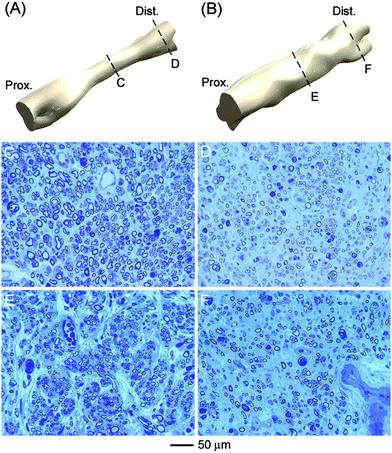 | ||
| Fig. 7 Isometric views of 3D reconstruction of regenerated nerve inside (A) silicone-, and (B) poly(ε-caprolactone)nanofiber-based nerve guidance conduits, respectively. Light microscopy images of cross sections of the regenerated nerve from middle (left side) and distal (right side) parts of the (C, D) silicone and (E, F) nanofiber-based conduits. | ||
While correlating well with in vitro studies of nanofiber scaffolds, this mechanism of nerve regeneration represents a significant departure from what has been observed for silicone NGCs. Despite the difference in the neuro-regenerative mechanism, multi-layered NGCs were demonstrated to preserve the quantity, quality, and maturity of axons regenerating across the imposed nerve defect 8 weeks post-operatively. Fig. 7C and E, shows optical micrographs of ultra-thin epoxy sections of regenerative nerve tissue obtained at mid-conduit from implanted silicone NGCs and multi-layered NGCs, respectively, while Fig. 7D and F, shows similar micrographs of regenerative nerve tissue obtained 5 mm distal to mid-conduit from implanted silicone NGCs and multi-layered NGCs, respectively. These preliminary results suggest that multi-layered NGCs performed as well as, if not better than silicone NGCs in vivo, and that the NGCs possibly employ a mechanism of neuro-regeneration which might allow for superior levels of nerve regeneration under optimal conditions.
In addition to the histological studies, pilot studies conducted by our group have indicated that the multi-layered NGCs support functional recovery following peripheral nerve injury repair. Electrophysiological studies conducted with such NGCs in situ confirmed that the regenerative nerve tissue contained in the implanted nanofiber-based NGCs was capable of conducting compound neural action potentials (CNAPs) with a near physiological conduction velocity. Furthermore, successful evocation of the twitch and tetanic responses in the extensor digitorum longus muscle upon stimulation of the sciatic nerve proximal to the implanted conduit indicates that the nanofiber-based NGCs supported robust regeneration of motor axons across the nerve defect, as well as functional reinnervation of distal motor targets. Both CNAP conduction and evoked muscle force measurements additionally correlated well with observations of improved ambulation in animals, as measured by walking track assessment and calculation of sciatic function index (SFI) scores. Taken together, these results positively confirm the ability of the nanofiber-based NGCs to promote recovery in sensorimotor function following nerve injury repair; a point infrequently addressed by studies investigating the use of nanofiber-based NGCs. Quantitative analysis of conducted CNAP and evoked muscle force amplitude demonstrated that multi-layered, nanofiber-based NGCs provided superior functional recovery to standard silicone NGCs.
NGCs based on electrospun nanofibers may represent a new approach to improving the treatment of peripheral nerve injury in vivo through their ability to promote an alternative mechanism of axonal regeneration upon implantation into peripheral nerve tissue. Yet, while preliminary data have demonstrated the vast potential of nanofiber substrates as NGC materials, additional studies are required to optimize the design and fabrication of such NGCs. Additionally, a recent study demonstrated that the transplantation of ESCs improves nerve repair and functional recovery after severe sciatic nerve axotomy.45 Electrospun nanofiber scaffolds in conjunction with ESC therapy and/or sustained delivery of NGF could provide a promising route for peripheral nerve injury repair. Through further investigations, neuroregenerative nanofiber-based NGCs could be designed such to rival or surpass the regenerative capabilities of peripheral nerve allografts, therefore promoting nanofiber-based NGCs as a clinically-viable therapy for injuries of the peripheral nervous system.
In addition to the use in a peripheral nervous system, electrospun nanofiber scaffolds may be useful in the repair and regeneration of the central nervous system (CNS). However, the use of electrospun nanofibers for spinal cord injury repair is still in its infancy. Recently, Meiners et al. discussed the design of implants comprised of biodegradable electrospun nanofibers for the purpose of bridging injuries of the spinal cord.46 Their preliminary work demonstrated that polyamidenanofibers covalently modified with neuroactive molecules provided a promising scaffold for promoting spinal cord regeneration. However, it was found that the random orientation of the nanofiber fabric folds was an impediment to the forward movement of axons. In the spinal cord, axonal tracing usually follows a strict topography. Hereafter, grafts should be able to recapitulate the in vivo microenvironment in order to allow reconnection of axons to the appropriate targets and to gain maximum functional recovery after injury repair. For the appropriate guidance of regenerated axons, efforts should be directed toward the engineering of ordered nanofiber structures in combination with the sustained delivery of neurotrophic factors and cell-based therapies. To this end, a blend of the nanofibers with cells could be used as an ideal cell construct for repairing spinal cord injury. Fig. 8 shows microscopy images of multi-layered cell-fiber constructs.47 This idea could be extended to fabricate multi-layered cell-fiber constructs for spinal cord injury repair.
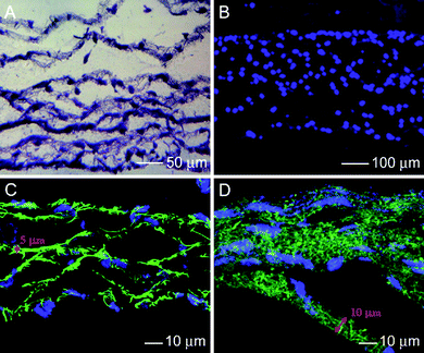 | ||
| Fig. 8 (A) Fluorescence micrograph of the cross section of a fiber-cell construct stained with hematoxylin for cell nucleus in blue color. (B) Fluorescence micrograph of a DAPI-stained cross section of the fiber-cell construct cultured for 2 days. (C, D) Confocal microscopy images of cross sections of the cell-fiber construct with a controlled thickness for the fiber layer. The fibers were labeled with FITC in green color and the cells were stained in blue color by DAPI. Adapted with permission from ref. 47. Copyright Mary Ann Liebert (2009). | ||
7. Concluding remarks
In summary, electrospun nanofibers have significant implications for understanding and control of neurite outgrowth and for use in nerve regeneration. The potential use of electrospinning for fabricating NGCs can be greatly enhanced by combining electrospun mats with many other well-established techniques (e.g., functionalization of fibers and cell implantation). The composition, morphology, and structure of the fibers can all be tailored using a number of physical and chemical methods. Surface modification has been exploited to provide a simple route to promote neurite outgrowth, while control of fiber alignment has been utilized to guide neurite extension. All these research activities have led to the exploration of scaffolds based on electrospun nanofibers for applications to neural tissue engineering. Although electrospun nanofibers have been demonstrated to be capable of guiding and promoting neurite or axonal growth in vitro, only a few in vivo studies have been carried out to date. More efforts should be directed toward testing conduits based on electrospun nanofibers for peripheral nerve injury repair in vivo. Additionally, there is a strong need for improving the conduit design in the following aspects: a suitable degradation profile, optimization of the fiber organization for better guidance of regenerative axon growth, and application of external cues for further enhancing axonal extension and guidance.Acknowledgements
This work was supported in part by a 2006 NIH Director's Pioneer Award (DP1 OD000798) and start-up funds from Washington University in St. Louis. Part of the work was performed at the Nano Research Facility (NRF), a member of the National Nanotechnology Infrastructure Network (NNIN), which is supported by the NSF under award no. ECS-0335765. NRF is part of School of Engineering and Applied Science at Washington University in St. Louis.References
- G. R. Evans, Anat. Rec., 2001, 263, 396–404 CrossRef CAS.
- C. E. Schmidt and J. B. Leach, Annu. Rev. Biomed. Eng., 2003, 5, 293–347 CrossRef CAS.
- (a) G. R. Evans, Semin. Surg. Oncol., 2000, 19, 312–318 CrossRef CAS; (b) P. C. Francel, K. S. Smith, F. A. Stevens, S. C. Kim, J. Gossett, C. Gossett, M. E. Davis, M. Lenaerts and P. Tompkins, J. Neurosurg., 2003, 99, 549–554 CrossRef; (c) R. V. Bellamkonda, Biomaterials, 2006, 27, 3515–3518 CAS.
- G. Lundborg, J. Hand Surg., 2000, 25, 391–414 CAS.
- (a) G. C. Ruiter, I. A. Onyeneho, E. T. Liang, M. J. Moore, A. M. Knight, M. J. A. Malessy, R. J. Spinner, L. Lu, B. L. Currier, M. J. Yaszemski and A. J. Windebank, J. Biomed. Mater. Res., 2007, 85A, 643–651 Search PubMed; (b) T. B. Ngo, P. J. Waggoner, A. A. Romero, K. D. Nelson, R. C. Eberhart and G. M. Smith, J. Neurosci. Res., 2003, 72, 227–238 CrossRef CAS; (c) T. B. Bini, S. Gao, X. Xu, S. Wang, S. Ramakrishna and K. W. Leong, J. Biomed. Mater. Res., 2004, 68a, 286–295 Search PubMed; (d) N. Zhang, C. Zhang and X. Wen, J. Biomed. Mater. Res., Part A, 2005, 75a, 941–949 CrossRef CAS; X. Wen and P. A. Tresco, Biomaterials, 2006, 27, 3800–3809 CrossRef CAS; (e) M. C. Lu, Y. T. Huang, J. H. Lin, C. H. Yao, C. W. Lou, C. C. Tsai and Y. S. Chen, J. Mater. Sci.: Mater. Med., 2009, 20, 1175–1180 CrossRef CAS.
- (a) J. S. Taras, V. Nanavati and P. Steelman, J. Hand Ther., 2005, 18, 191–197 Search PubMed; (b) M. F. Meek and J. H. Coert, J. Reconstr. Microsurg., 2002, 18, 97–109 CrossRef CAS.
- S. Panseri, C. Cunha, J. Lowery, U. D. Carro, F. Taraballi, S. Amadio, A. Vescovi and F. Gelain, BMC Biotechnol., 2008, 8, 39–51 CrossRef.
- (a) J. Xie, X. Li and Y. Xia, Macromol. Rapid Commun., 2008, 29, 1769–1848; (b) S. G. Kumbar, R. James, S. P. Nukavarapu and C. T. Laurencin, Biomed. Mater., 2008, 3, 034002 Search PubMed.
- (a) D. Li and Y. Xia, Adv. Mater., 2004, 16, 1151–1170 CrossRef CAS; (b) C. Burger, B. S. Hsiao and B. Chu, Annu. Rev. Mater. Res., 2006, 36, 333–368 CrossRef CAS.
- D. Li, J. T. McCann and Y. Xia, J. Am. Ceram. Soc., 2006, 89, 1861–1869 CrossRef CAS.
- (a) A. L. Yarin, S. Koombhongse and D. H. Reneker, J. Appl. Phys., 2001, 89, 3018–3026 CrossRef CAS; (b) D. H. Reneker, A. L. Yarin, H. Fong and S. Koobhongse, J. Appl. Phys., 2000, 87, 4531–4547 CrossRef CAS.
- T. Han, D. H. Reneker and A. L. Yarin, Polymer, 2007, 48, 6064–6076 CrossRef CAS.
- S. Megelski, J. S. Stephens, D. B. Chase and J. F. Rabolt, Macromolecules, 2002, 35, 8456–8466 CrossRef CAS.
- J. T. McCann, M. Marquez and Y. Xia, J. Am. Chem. Soc., 2006, 128, 1436–1437 CrossRef CAS.
- B. Dong, M. E. Smith and G. E. Wnek, Small, 2009, 5, 1508–1512 CrossRef CAS.
- J. Xie, M. R. MacEwan, S. M. Willerth, X. Li, D. Moran, S. E. Sakiyama-Elbert and Y. Xia, Adv. Funct. Mater., 2009, 19, 2312–2318 CrossRef CAS.
- D. H. Reneker and A. L. Yarin, Polymer, 2008, 49, 2387–2425 CrossRef CAS.
- W. E. Teo and S. Ramakrishna, Nanotechnology, 2006, 17, R89 CrossRef CAS.
- D. Li, Y. Wang and Y. Xia, Nano Lett., 2003, 3, 1167 CrossRef CAS.
- D. Li, Y. Wang and Y. Xia, Adv. Mater., 2004, 16, 361–366 CrossRef CAS.
- C. K. Hashi, Y. Zhu, G. Y. Yang, W. L. Young, B. S. Hsiao, K. Wang, B. Chu and S. Li, Proc. Natl. Acad. Sci. U. S. A., 2007, 104, 11915–11920 CrossRef CAS.
- S. Y. Chew, R. Mi, A. Hoke and K. W. Leong, Adv. Funct. Mater., 2007, 17, 1288–1296 CrossRef CAS.
- W. E. Teo, M. Kotaki and S. Ramakrishna, Nanotechnology, 2005, 16, 918–924 CrossRef CAS.
- D. Zhang and J. Chang, Nano Lett., 2008, 8, 3283–3287 CrossRef CAS.
- (a) S. M. Willerth, T. E. Faxel, D. I. Gottlieb and S. E. Sakiyama-Elbert, Stem Cells, 2007, 25, 2235–2244 Search PubMed; (b) P. Murray and D. Edgar, Philos. Trans. R. Soc. London, Ser. B, 2004, 359, 1009–1020 CrossRef CAS; (c) M. Yamada, K. Tanemura, S. Okada, A. Iwanami, M. Nakamura, H. Mizuno, M. Ozawa, R. Ohyama-Goto, N. Kitamura, M. Kawano, K. Tan-Takeuchi, C. Ohtsuka, A. Mitawaki, A. Takashima, M. Ogawa, Y. Toyama, H. Okano and T. Kondo, Stem Cells, 2007, 25, 562–570 Search PubMed; (d) A. J. Engler, S. Sen, H. L. Sweeney and D. E. Discher, Cell, 2006, 126, 677–689 CrossRef CAS.
- J. Xie, S. M. Willerth, X. Li, M. R. MacEwa, A. Rader, S. E. Sakiyama-Elbert and Y. Xia, Biomaterials, 2009, 30, 354–362 CrossRef CAS.
- G. T. Christopherson, H. Song and H. Q. Mao, Biomaterials, 2009, 30, 556–564 CrossRef CAS.
- K. Alberti, R. E. Davey, K. Onishi, S. George, K. Salchert, F. P. Seib, M. Bornhauser, T. Pompe, A. Nagy, C. Werner and P. W. Zandstra, Nat. Methods, 2008, 5, 645–650 CrossRef CAS.
- F. Yang, R. Murugan, S. Wang and S. Ramakrishna, Biomaterials, 2005, 26, 2603–2610 CrossRef CAS.
- (a) J. M. Corey, D. Y. Lin, K. B. Mycek, Q. Chen, S. Samuel, E. L. Feldman and D. C. Martin, J. Biomed. Mater. Res., Part A, 2007, 83a, 636–645 CrossRef CAS; (b) W. N. Chow, D. G. Simpson, J. W. Bigbee and R. J. Colello, Neuron Glia Biol., 2007, 3, 119–126 Search PubMed.
- H. B. Wang, M. E. Mullins, J. M. Cregg, A. Hurtado, M. Outdega, M. T. Trombley and R. J. Gilbert, J. Neural Eng., 2009, 6, 016001 Search PubMed.
- J. Xie, M. R. MacEwan, X. Li, S. E. Sakiyama-Elbert and Y. Xia, ACS Nano, 2009, 3, 1151–1159 CrossRef CAS.
- M. P. Prabhakaran, J. Venugopal, C. K. Chan and S. Ramakrishna, Nanotechnology, 2008, 19, 455102 CrossRef.
- S. Patel, K. Kurpinski, R. Quigley, H. Gao, B. S. Hsiao, M. M. Poo and S. Li, Nano Lett., 2007, 7, 2122–2128 CrossRef CAS.
- I. Ahmed, H. Liu, P. C. Mamiya, A. S. Ponery, A. N. Babu, T. Weik, M. Schindler and S. Meiners, J. Biomed. Mater. Res. A., 2006, 76, 851–860 CrossRef.
- E. Schnell, K. Klinkhammer, S. Balzer, G. Brook, K. Klee, P. Dalton and J. Mey, Biomaterials, 2007, 28, 3012–3025 CrossRef CAS.
- H. S. Koh, T. Yong and S. Ramakrishna, Biomaterials, 2008, 29, 3574–3582 CrossRef CAS.
- M. P. Prabhakaran, J. R. Venugopal, T. T. Chyan, L. B. Hai, C. K. Chan, A. Y. Lim and S. Ramkrishna, Tissue Eng. A, 2008, 14, 1787–1797 Search PubMed.
- (a) J. Y. Lee, C. Bashur, A. Goldstein and C. E. Schmidt, Biomaterials, 2009, 30, 4325–4335 CrossRef CAS; (b) Y. Liu, X. Liu, J. Chen, K. J. Gilmore and G. G. Wallace, Chem. Commun., 2008, 3729–3731 RSC.
- T. B. Bini, S. Gao, T. C. Tan, S. Wang, A. Lim, L. B. Hai and S. Ramakrishna, Nanotec hnology, 2004, 15, 1459–1464 CrossRef CAS.
- (a) H. K. Bae and D. J. Chung, IFMBE Proc., 2007, 14, 3354–3357 Search PubMed; (b) W. Wang, S. Itoh, A. Matsuda, S. Ichinose, K. Shinomiya, Y. Hata and J. Tanaka, J. Biomed. Mater. Res., Part A, 2008, 84a, 557–566 CrossRef CAS.
- Y. Kim, V. K. Haftel, S. Kumar and R. V. Bellamkonda, Biomaterials, 2008, 29, 3117–3127 CrossRef CAS.
- (a) L. Yao, N. O'Brien, A. Windebank and A. Pandit, J. Biomed. Mater. Res. B: Appl. Biomater., 2009, 90, 483–491 CrossRef; (b) W. Wang, S. Itoh, K. Konno, T. Kikkawa, S. Ichinose, K. Sakai, T. Ohkuma and K. Watabe, J. Biomed. Mater. Res., Part A, 2008 DOI:10.1002/jbm.a.32329.
- J. S. Belkas, M. S. Schoichet and R. Midha, Oper. Tech. Orthop., 2004, 14, 190–198 Search PubMed.
- L. Cui, J. Jiang, L. Wei, X. Zhou, J. L. Fraser, B. J. Snider and S. P. Yu, Stem Cells, 2008, 26, 1356–1365 Search PubMed.
- S. Meiners, I. Ahmed, A. S. Ponery, N. Amor, S. L. Harris, V. Ayres, Y. Fan, Q. Chen, R. Delgado-Rivera and A. N. Babu, Polym. Int., 2007, 56, 1340–1348 CrossRef CAS.
- X. Yang, J. D. Shah and H. Wang, Tissue Eng. A, 2009, 15, 945–955 Search PubMed.
| This journal is © The Royal Society of Chemistry 2010 |
