In situ generation of pH gradients in microfluidic devices for biofabrication of freestanding, semi-permeable chitosan membranes
Xiaolong
Luo
a,
Dean Larios
Berlin
b,
Jordan
Betz
b,
Gregory F.
Payne
a,
William E.
Bentley
*ab and
Gary W.
Rubloff
*cd
aUniversity of Maryland Biotechnology Institute (UMBI), University of Maryland, College Park, MD 20742, USA
bFischell Department of Bioengineering, University of Maryland, College Park, MD 20742, USA. E-mail: bentley@umd.edu; Fax: +1 301 405 9953; Tel: +1 301 405 4321
cInstitute for Systems Research (ISR), University of Maryland, College Park, MD 20742, USA
dDepartment of Materials Science and Engineering, University of Maryland, College Park, MD 20742, USA. E-mail: rubloff@umd.edu; Fax: +1 301 314 9920; Tel: +1 302 405 3011
First published on 3rd November 2009
Abstract
We report the in situ generation of pH gradients in microfluidic devices for biofabrication of freestanding, semi-permeable chitosan membranes. The pH-stimuli-responsive polysaccharide chitosan was enlisted to form a freestanding hydrophilic membrane structure in microfluidic networks where pH gradients are generated at the converging interface between a slightly acidic chitosan solution and a slightly basic buffer solution. A simple and effective pumping strategy was devised to realize a stable flow interface thereby generating a stable, well-controlled and localized pH gradient. Chitosan molecules were deprotonated at the flow interface, causing gelation and solidification of a freestanding chitosan membrane from a nucleation point at the junction of two converging flow streams to an anchoring point where the two flow streams diverge to two output channels. The fabricated chitosan membranes were about 30–60 µm thick and uniform throughout the flow interface inside the microchannels. A T-shaped membrane formed by sequentially fabricating orthogonal membranes demonstrates flexibility of the assembly process. The membranes are permeable to aqueous solutions and are removed by mildly acidic solutions. Permeability tests suggested that the membrane pore size was a few nanometres, i.e., the size range of antibodies. Building on the widely reported use of chitosan as a soft interconnect for biological components and microfabricated devices and the broad applications of membrane functionalities in microsystems, we believe that the facile, rapid biofabrication of freestanding chitosan membranes can be applied to many biochemical, bioanalytical, biosensing applications and cellular studies.
Introduction
The integration of membrane functionality into microfluidics has attracted substantial attention in the last decade. Mass transport control is achieved by integrated membranes for applications such as filtration,1–4 microdialysis,5,6 extraction7 and gas–liquid exchange.8 Approaches to membrane integration include direct incorporation of commercial membranes or forming membranes as part of the bioMEMS chip fabrication process, both of which pose difficulty in packaging the microfluidic chips or extra complexity and cost in fabrication.9 Recently, in situ photopolymerization and thermo-gelation have been investigated to form porous structures in microchannels.10,11 For example, membrane-like hydrogels produced by ultraviolet photopolymerization12,13 or thermo-sensitive gelation11,14–16 in microfluidics have emerged for creating 3D cell culture environments. However, in many cases the ultraviolet photopolymerization and thermo-initiative gelation are cytotoxic.11–13,15,16 Moreover, the composition and properties of animal-derived collagen by thermo-gelation are difficult to control.11,15,16Using laminar flow patterning in microfluidics for in situ microfabrication was originally reported by Whitesides et al.17,18 and has recently been exploited for fabrication of polymer membranes in microfluidic devices.19–22 Most membranes in microfluidics are made of non-biological materials, or are fabricated via non-biological routes. In the case of in situ membrane microfabrication, the lingering initiators and monomer residues from either photopolymerization or polymer chain reactions might be toxic to subsequent biological applications, and subsequent modification of the formed membrane is required for biomolecular assembly.19 Therefore, a natural fabrication process—using biological or biocompatible materials—is highly desirable for biomolecular applications and cell manipulation.23
Here we exploit the in situ generation of pH gradients as the driving force for membrane assembly in microfluidic devices. Electrochemically generated pH gradients were formed by electrical signals in microfluidic channels under flowing conditions for isoelectric focusing24 and transverse isoelectric focusing (IEF).25 Non-electrochemical generation of pH or other chemical gradients inside microfluidic networks has been demonstrated by converging multiple flow streams within a gradient generator.26,27 The generation of gradients with laminar flow systems has continued to evolve and expand to broad applications.28–31
Biofabrication is an emerging paradigm which exploits biologically derived materials and biocatalysts for fabrication and offers opportunities to access a wider range of fabrication options.32 Self-assembly,33 enzymatic assembly34 and directed assembly35–38 are typical biofabrication approaches that have been broadly exploited to assemble biological species onto solid surfaces. For example, stimuli-responsive alginate gels can be formed in microfluidic channels.39–42 Chitosan, a natural biomaterial is another ideal candidate material whose pH-responsive properties make it uniquely valuable in biofabrication. Recently, we have demonstrated that the amino polysaccharide chitosan is a key enabling material for biofabrication.32 Chitosan is a linear β-1,4-linked polysaccharide that is obtained by partial deacetylation of chitin. As shown in Scheme 1(a), chitosan has abundant primary amine groups at the C-2 position of the glucosamine residues, enabling important functional properties of chitosan to be exploited for biofabrication.43 At low pH, these amines are protonated and positively charged, and chitosan is a water-soluble cationic polyelectrolyte. At higher pH than the pKa of ∼6.3, chitosan's amines become deprotonated, so that the polymer loses its charge and becomes insoluble with gel or film forming characteristics. By utilizing the pH-dependent solubility of chitosan combined with electrical signals to control local pH at electrodes, our research groups have exploited the stimuli-responsive directed assembly of chitosan at electrode surfaces in microchips33,36,44–47 and bioMEMS devices.36–38,48
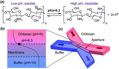 | ||
| Scheme 1 (a) Polysaccharide chitosan with pH-responsive solubility; (b) a top view and (c) a 3D perspective view of the pH gradient across aperture openings between the buffer and chitosan flow streams. | ||
This paper reports the in situ microfabrication of freestanding, semi-permeable chitosan membranes by pH gradients across aperture openings in microfluidic networks (as shown in Scheme 1(b)). By utilizing the unique pH-dependent solubility of chitosan, we demonstrate that hydrophilic permeable biopolymer membranes can be formed in microfluidic networks by pH gradients generated at the converging interface between a slightly acidic chitosan solution and a slightly basic solution. Both a stable flow interface and a pH gradient were realized by incorporating a simple and reliable pumping strategy that exposes the acidic chitosan solution to an adjacent basic buffer. The resultant biofabricated chitosan membranes were found to be uniform throughout the flow interface, permeable to aqueous solutions and removable by mildly acidic solutions. Permeability tests further confirmed the pore size of the membranes to be a few nanometres, similar to the size of proteins (antibodies). Building on the use of chitosan as a soft interconnect for biological components32,33,35–37,46,48–50 and the broad applications of membrane functionalities in microsystems,1–7,11–16 we believe that the facile, rapid in situ biofabrication of freestanding chitosan membranes in microfluidics can be applied to many biochemical, bioanalytical and biosensing applications.
Materials and methods
Chemicals
Chitosan (medium molecular weight, average molecular weight 300![[thin space (1/6-em)]](https://www.rsc.org/images/entities/char_2009.gif) 000 g mol−1), phosphate buffered saline tablets (10 mM phosphate buffer, 2.7 mM KCl and 137 mM NaCl, pH 7.4), fluorescein (for fluorescence, free acid, λex = 490 nm/λem = 514 nm in 0.1 M Tris pH 8.0) and universal pH indicator (pH 4–10) were purchased from Sigma Aldrich. Sodium hydroxide and hydrochloric acid were purchased from Fisher Scientific. PDMS kits (Sylgard 184 and curing agent) were purchased from Dow Corning. Microbore PTFE tubing (0.022″ ID/0.042″ OD) was purchased from Cole-Parmer, IL. Genie syringe pumps were purchased from Kent Scientific, CT. Micro-glass slides and single-use syringes were purchased from VWR®, PA. 5-(and 6-)Carboxyfluorescein succinimidyl ester (NHS-fluorescein, wavelengths of 495 nm and 519 nm) and FluoSphere® polystyrene nanospheres (20 nm diameter, yellow-green fluorescent (λex = 505 nm/λem = 515 nm, %2 solids) were purchased from Invitrogen Corp., CA and stored in a desiccator at −20 °C in a dark container until use. Stainless steel catheter plugs (20 ga × 12 mm) were purchased from Instech Solomon, PA. A Harris Uni-core punch (1.0 mm) was purchased from Ted Pella Inc., CA.
000 g mol−1), phosphate buffered saline tablets (10 mM phosphate buffer, 2.7 mM KCl and 137 mM NaCl, pH 7.4), fluorescein (for fluorescence, free acid, λex = 490 nm/λem = 514 nm in 0.1 M Tris pH 8.0) and universal pH indicator (pH 4–10) were purchased from Sigma Aldrich. Sodium hydroxide and hydrochloric acid were purchased from Fisher Scientific. PDMS kits (Sylgard 184 and curing agent) were purchased from Dow Corning. Microbore PTFE tubing (0.022″ ID/0.042″ OD) was purchased from Cole-Parmer, IL. Genie syringe pumps were purchased from Kent Scientific, CT. Micro-glass slides and single-use syringes were purchased from VWR®, PA. 5-(and 6-)Carboxyfluorescein succinimidyl ester (NHS-fluorescein, wavelengths of 495 nm and 519 nm) and FluoSphere® polystyrene nanospheres (20 nm diameter, yellow-green fluorescent (λex = 505 nm/λem = 515 nm, %2 solids) were purchased from Invitrogen Corp., CA and stored in a desiccator at −20 °C in a dark container until use. Stainless steel catheter plugs (20 ga × 12 mm) were purchased from Instech Solomon, PA. A Harris Uni-core punch (1.0 mm) was purchased from Ted Pella Inc., CA.
Chitosan preparation
A 0.5% chitosan solution was prepared by adding chitosan flakes to de-ionized water, with HCl added dropwise to maintain pH ≈ 3; they were mixed overnight. The pH was then adjusted to 5 by the dropwise addition of 1 M NaOH. DI water was added to bring the mixture to 0.5%. The resulting chitosan solution was then filtered and stored at 4 °C. Fluorescently labeled chitosan was prepared by reacting NHS-fluorescein with chitosan to produce up to 6% labeled chitosan so that the pH-dependent responsiveness was retained. Details of the labeling procedure were previously reported.45TRITC-labeled antibody
Polyclonal rabbit anti Escherichia coli antibody was purchased from AbD Serotec, Oxford, UK. Alexa Fluoreporter Texas Red (wavelengths of 577 nm and 603 nm) protein labeling kit was purchased from Invitrogen. TRITC labeling of anti E. coli antibody was performed as per the manufacturer's specification (Invitrogen).Microfluidic device fabrication
The microchannels were fabricated with polydimethylsiloxane (PDMS) via soft lithography. The angle between the two converging (dividing) microchannels was either 30° or 60°. PDMS microchannels were cured, delaminated from patterned SU-8 molds and punched with input–output holes. For most of the devices, the PDMS microchannels (500 µm wide, 85 µm or 135 µm high) were permanently bonded to piranha-cleaned glass slides by oxygen plasma treatment (450 mTorr pressure, 20 W power, 20 sccm oxygen flow rate for 30 s) using a Trion RIE machine. For the devices used to investigate the membrane microstructure when we wanted to remove the membrane, the PDMS microchannels were non-permanently sandwiched between a PDMS layer and a glass slide which, in turn, were compressed between two Plexiglas plates by screws. Liquid flows into the device were through flexible PTFE tubing.Pumping setup
A novel pumping strategy shown in Fig. 1(a) was devised to produce a stable flow interface and pH gradient. An air plug of ∼2 cm3 was introduced into each syringe and the pumps were mounted vertically to position the air plug above the liquid. This damped the pulsatile flow often accompanying stepper motors and peristaltic pumps. Fig. 1(b) shows a stable, well-balanced flow interface between two dye solutions using this pumping strategy. The extra fluid input (the center microchannel in Fig. 1(a)) is used to introduce acidic solutions to dissolve and remove chitosan membranes for subsequent experimentation. Due to the apparent differences in viscosity of the chitosan (0.5% w/v, pH 4.9) and buffer solutions (pH 10), the buffer flow rates are much higher than the chitosan flow rates. We typically set the chitosan solution to 10–30 µL min−1 and the buffer to 100–250 µL min−1.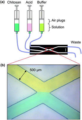 | ||
| Fig. 1 Experimental setup: (a) pumping setup to form a chitosan membrane at a stable flow interface with compressible air plugs in vertically mounted syringe pumps; (b) flow interface between yellow (top) and blue (bottom) dye solutions well-balanced in microfluidic channels. | ||
Membrane microstructure investigation
To investigate the microstructure of the fabricated membrane, we developed a simple extraction procedure using the non-permanently sandwiched devices as noted above. After a membrane was fabricated using the non-permanently bonded device as described above, the microchannels were filled with DI water, disconnected from the syringe pumps and sealed with metal plugs. Next, the microfluidic device was stored at −20 °C in a freezer for 2 h to encase the membrane in ice. The intact membrane was recovered by first disassembling the whole device in an ice bath and then carefully detaching the PDMS microchannel from the glass slide. The chitosan membrane was thawed in PBS buffer for observation by optical microscopy. This freeze–thaw procedure was adapted from the literature19 since direct opening of non-permanently sealed microchannels tends to tear the membrane and leave the membrane partially attached to the microchannel ceiling (PDMS) and/or the floor (glass slide).Membrane permeability tests
Membrane permeability tests were performed by introducing a test solution from one input, closing the other input stream and leaving both outputs open. The first two tests were sequentially performed on the same membrane with solutions containing small fluorescein molecules (MW 332, 0.2 mM) and red fluorescently labeled polyclonal antibodies (∼150 kDa, 2 µM), respectively, pumped at 4 µL min−1 flow rate into the microchannels. A third test was performed with a solution containing 20 nm (diameter) polystyrene nanospheres pumped at 4 µL min−1 flow rate into the microchannels. In all the cases, the device was viewed under a Zeiss 310 optical microscope with appropriate filter sets. These tests were repeated three times.Results
pH gradient generation in a microfluidic device
By applying the pumping strategy that incorporates compressible air plugs in vertically mounted syringe pumps, we first generated a stable pH gradient between adjacent flow streams of a basic solution and an acidic solution in a microfluidic device as shown in Fig. 2. For this, a middle flow stream of universal pH indicator (active at pH 4–10) was introduced into the center microchannel (Fig. 2(a)) while the basic buffer solution (pH 10) was introduced into the upper-left microchannel and the acidic buffer solution (pH 4) was introduced into the lower-left microchannel. As indicated in Fig. 2(b), a stable pH gradient was generated at the interface between the upper basic buffer solution and the lower acidic buffer solution. A magnified view of the pH indicator flow stream in Fig. 2(c) clearly indicates the pH gradient from pH 4 (pink) of the acidic buffer solution to pH 10 (blue) of the basic buffer solution.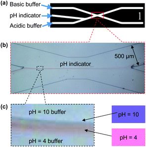 | ||
| Fig. 2 Generation of a pH gradient in microfluidics: (a) introduction of test solutions: basic buffer (pH = 10) to the upper-left channel, universal pH indicator (active pH 4–10) to the center-left channel and acidic buffer (pH = 4) to the lower-left channel; (b) well-balanced flow streams with a pH gradient generated in the middle of the microchannel network; (c) magnified view of the well-defined pH gradient from pH 4 (pink) to pH 10 (blue) generated between the acidic and basic buffer solutions. | ||
Biofabrication of straight and T-shape chitosan membranes by a pH gradient at the flow interface
Using this pH gradient, in Fig. 3 we demonstrate the biofabrication of chitosan membranes at the flow interface. Adjacent flow streams of (1) a NHS fluorescent-labeled, slightly acidic chitosan solution (pH 5) and (2) a relatively basic buffer solution (pH 10) are allowed to contact each other for varied times. Chitosan molecules are deprotonated at the flow interface, causing gelation and solidification of a freestanding vertical chitosan membrane. We refer to the membrane as vertical because it is perpendicular to the plane of the microfluidics network. Fig. 3(a) illustrates the typical membrane growth. The PDMS surface at the junction of the two laminar flow streams acts as the nucleation point for membrane growth, where deprotonated chitosan molecules self-assemble onto the PDMS surface. Growth of the freestanding membrane proceeds throughout the flow interface from the upstream nucleation point to the downstream anchoring point where the two laminar streams diverge to the two output channels. An extra fluid input (a third microchannel) is used to introduce acidic solutions to dissolve and remove chitosan membranes when desired. The formation of a 1.25 mm long, 30 µm thick and 85 µm high (microchannel height) chitosan membrane shown in Fig. 3(a) was completed within 10 min. The flow rates used to form this membrane are 10 µL min−1 for the fluorescent-labeled chitosan and ∼160 µL min−1 for the basic buffer. The angle between the two converging (and dividing) microchannels is 60°.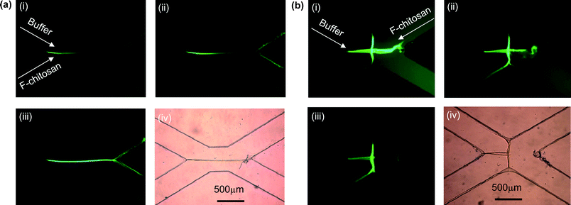 | ||
| Fig. 3 In situ biofabrication of (a) a straight chitosan membrane and (b) a T-shape chitosan membrane in microfluidics with a NHS fluorescently labeled, slightly acidic chitosan solution (pH ≈ 5). The formation of the T-shape membrane was achieved by switching the chitosan input from the lower-left channel to the upper-right channel, which demonstrates that the fabricated membrane is permeable to aqueous basic buffer solution and removable by acid chitosan solution. | ||
The biofabricated chitosan membrane was found to be permeable to aqueous solutions and removable by mildly acidic solutions. The permeability and manufacturing flexibility of these chitosan membranes were demonstrated by the formation of a T-shaped chitosan membrane inside a microfluidic device shown in Fig. 3(b). After a straight membrane was formed with fluorescently labeled chitosan solution, the same chitosan solution was introduced at a reduced flow rate of 3 µL min−1 from the upper-right channel instead of the lower-left channel. The basic buffer solution was also introduced at a reduced flow rate of 20 µL min−1 from the upper-right channel as before, but was exited through the lower-left channel. In this way, the two fluids move from top to bottom and out. The whole process was monitored under optical microscopy and no displacement of the assembled membrane was observed. The results in Fig. 3(b) illustrate that (1) the right side of the original membrane was dissolved by the acidic chitosan solution, (2) the left side of the original membrane was permeable to the basic buffer solution, and (3) a new membrane was formed at the new interface between the buffer solution and chitosan solution (and are perpendicular to the original membrane). This procedure allows for sequential construction of more complex geometries without opening the device, or breaking the seals. By judicious sequencing of input chitosan, buffer and acid fluids, and careful balancing of the formation and dissolution rates, other complex structures can be assembled from these building blocks.
Fig. 4 shows the microstructure of the chitosan membrane formed by this approach within a non-permanently packaged microfluidic device. The intact membrane was recovered by filling the microchannels with DI water, freezing the whole device in a −20 °C refrigerator, dissembling the packaging in an ice bath and thawing the iced material containing the intact membrane. The membrane on the PDMS was then tilted at a 45° angle for observation under a microscope. The membrane was found to be uniform throughout, with a width of ∼40 µm as shown in the top view image and a height of ∼85 µm (microchannel height). This structure was similarly obtained in several repeated runs.
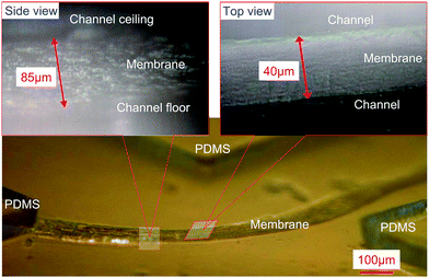 | ||
| Fig. 4 Light micrographs of a freestanding chitosan membrane. | ||
Control and reproducibility of membrane thickness
Fig. 5 shows the time-dependent growth of membrane thickness at various chitosan and basic buffer flow rates. For this, the chitosan membranes were fabricated by either varying basic buffer flow rates with set chitosan flow rates (30 µL min−1, Fig. 5(a)) or varying chitosan flow rates with set basic buffer flow rates (200 µL min−1, Fig. 5(b)). Membrane thickness was monitored by optical microscopy during the 10 min fabrication process.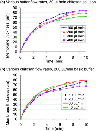 | ||
| Fig. 5 Time-dependent growth of membrane thickness at various chitosan and basic buffer flow rates. (a) 30 µL min−1 chitosan solution with 100–400 µL min−1 basic buffer; (b) 200 µL min−1 basic buffer with 10–40 µL min−1 chitosan solution. | ||
By careful examination of the assembly process, we observed that the emerging membrane thickness grew from the interface into the flow stream of the chitosan solution over time. We attribute this to the diffusion of hydroxyl ions through the fabricated membrane, causing solidification of chitosan molecules onto the growing membrane, while diffusion of chitosan polymer molecules is likely slower. Interestingly, the results show that the membrane thickness did not change significantly with either chitosan or buffer flow rates. Importantly, the results in Fig. 5 demonstrate reproducibility and robustness of the assembly process.
Permeability studies
Fig. 3(b) and Fig. 5 suggest that the fabricated chitosan membrane is permeable to aqueous solutions and hydroxyl ions. To estimate the pore size of the fabricated chitosan membranes, we performed a series of permeability studies as shown in Fig. 6. For all these studies, the input solutions were introduced from the lower-left channel and the two right channels were left open, while the upper-left channel was closed. The flow rates were monitored appropriately so that the membrane was not displaced at both ends of the open aperture. The devices used in these studies all have an angle of 30° between the two converging (dividing) microchannels.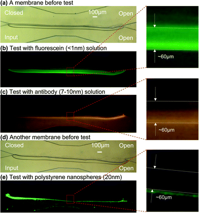 | ||
| Fig. 6 Permeability tests of a chitosan membrane. The membrane in (a) was used for (b) test with 20 µM fluorescein (molecular size <1 nm) solution and (c) test with 0.67 µM TRITC-labeled antibody (molecular size 7–10 nm) solution; membrane in (d) was used for (e) test with 2.63 × 10¹⁴ particles per mL FITC-labeled polystyrene nanospheres (particle size ∼20 nm) solution. All solutions were introduced at 5 µL min−1 flow rate. | ||
First, we fabricated a straight membrane of 2.5 mm long, 60 µm thick and 135 µm high (microchannel height) as shown in Fig. 6(a), and then introduced a solution containing small fluorescein molecules (20 µM, molecular size less than 1 nm) at 5 µL min−1 flow rate. Fig. 6(b) shows that the fluorescein solution passed quite freely through the membrane as its presence was noted throughout the fluidic network. Therefore, the fluorescence level was similar in the microchannels below and above the membrane, as indicated by a magnified area of the membrane in Fig. 6(b). Next, we introduced a solution containing TRITC-labeled antibodies (0.67 µM, molecular size 7–10 nm) at 5 µL min−1 flow rate to the same membrane as in Fig. 6(a). Fig. 6(c) shows that the antibodies only partially diffused through the membrane while more antibodies were retained at the bottom membrane surface.
Additionally, we fabricated a new straight membrane in a microchannel as shown in Fig. 6(d), and then introduced a solution containing FITC-labeled polystyrene nanospheres (2.63 × 10¹⁴ particles per mL, 20 nm in diameter) at 5 µL min−1 flow rate. Fig. 6(e) shows that the nanospheres were mostly retained at the bottom membrane surface with very few passing through. This is also indicated by the presence of very limited fluorescence in the microchannel above the membrane, as indicated by a magnified area of the membrane in Fig. 6(e). The test results of Fig. 6(c) and (e) also confirm that there were no gaps or holes in the assembled membranes.
The permeability studies were repeated three times with new membranes fabricated under identical conditions, and similar results were achieved. To summarize, the results from the permeability tests suggest that a representative pore size of the biofabricated chitosan membranes is a few nanometres, similar to the size of antibodies.
Discussion
These studies demonstrate the creation of biopolymer membranes using localized pH gradients in microfluidic networks. The membranes can be fabricated in situ and can form networks, gates, and guides. The process is biologically benign and simple. We note, however, that the fabricated chitosan membrane “network” can vary with the design of the device, pumping behavior of the solutions into the device, the pH values of the solutions and other factors, which again will shape the final membrane properties such as thickness, permeability and mechanical strength. Future work will address such issues in optimizing the membrane fabrication process for specific applications.We have previously developed simple, bio-inspired techniques to assemble biological components including proteins, nucleic acids, viruses and cells onto versatile chitosan scaffolds in microdevices.32,33,35–37,46,48–50 The facile membrane biofabrication strategy developed in this study potentially extends these capabilities to applications involving membranes within microfluidic devices. Broad applications in metabolic engineering and biosensing are foreseen by assembling active biological components such as biomarkers or enzymes onto these freestanding chitosan membranes. These are under active investigation.
Conclusions
We have demonstrated the in situ generation of pH gradients in microfluidic devices for biofabrication of freestanding, semi-permeable chitosan membranes. The fabricated chitosan membranes, in a range of 30 to 60 µm thick, were of uniform cross-section over a relatively long distance (a few mm) at the flow interfaces. We employed straight and T-shape membranes to demonstrate that they are permeable to aqueous solutions and removable by mildly acidic solutions. Moreover, these studies demonstrate the ease and flexibility of assembling various membrane geometries. Permeability studies suggest that the pore size of the membranes is a few nanometres, similar to the size of antibodies. We believe the facile, rapid biofabrication of freestanding chitosan membranes can be applied to many biochemical, bioanalytical, biosensing applications and cell-based studies.Acknowledgements
This work was supported in part by the Robert W. Deutsch Foundation and the NSF-EFRI program (#0735987). We acknowledge the support of the Maryland NanoCenter and its FabLab. The authors thank Dr Rohan Fernandes for preparing the fluorescently labeled antibody. We are also thankful for helpful discussions within the Rubloff and Bentley research teams with the Biochip Collaborative (http://www.biochip.umd.edu) at University of Maryland.References
- S. D. Noblitt, J. R. Kraly, J. M. VanBuren, S. V. Hering, J. L. Collett and C. S. Henry, Anal. Chem., 2007, 79, 6249–6254 CrossRef CAS.
- Z. C. Long, D. Y. Liu, N. N. Ye, J. H. Qin and B. C. Lin, Electrophoresis, 2006, 27, 4927–4934 CrossRef CAS.
- S. Thorslund, O. Klett, F. Nikolajeff, K. Markides and J. Bergquist, Biomed. Microdevices, 2006, 8, 73–79 CrossRef CAS.
- Y. C. Hsieh and J. D. Zahn, Biosens. Bioelectron., 2007, 22, 2422–2428 CrossRef CAS.
- R. Kurita, N. Yabumoto and O. Niwa, Biosens. Bioelectron., 2006, 21, 1649–1653 CrossRef CAS.
- Y. C. Hsieh and J. D. Zahn, Sens. Actuators, B, 2005, 107, 649–656 CrossRef.
- Z. X. Cai, Q. Fang, H. W. Chen and Z. L. Fang, Anal. Chim. Acta, 2006, 556, 151–156 CrossRef CAS.
- D. Lange, C. W. Storment, C. A. Conley and G. T. A. Kovacs, Sens. Actuators, B, 2005, 107, 904–914 CrossRef.
- J. de Jong, R. G. H. Lammertink and M. Wessling, Lab Chip, 2006, 6, 1125–1139 RSC.
- J. Moorthy and D. J. Beebe, Lab Chip, 2003, 3, 62–66 RSC.
- W. Tan and T. A. Desai, Biomed. Microdevices, 2003, 5, 235–244 CrossRef CAS.
- D. R. Albrecht, G. H. Underhill, T. B. Wassermann, R. L. Sah and S. N. Bhatia, Nat. Methods, 2006, 3, 369–375 CrossRef CAS.
- S. H. P. Chee Ping Ng, Biotechnol. Bioeng., 2008, 99, 1490–1501 CrossRef CAS.
- Y. Ling, J. Rubin, Y. Deng, C. Huang, U. Demirci, J. M. Karp and A. Khademhosseini, Lab Chip, 2007, 7, 756–762 RSC.
- K. Shibata, H. Terazono, A. Hattori and K. Yasuda, Jpn. J. Appl. Phys., 2008, 47, 5208–5211 CrossRef CAS.
- H. G. Sundararaghavan, G. A. Monteiro, B. L. Firestein and D. I. Shreiber, Biotechnol. Bioeng., 2009, 102, 632–643 CrossRef CAS.
- P. J. A. Kenis, R. F. Ismagilov, S. Takayama, G. M. Whitesides, S. L. Li and H. S. White, Acc. Chem. Res., 2000, 33, 841–847 CrossRef CAS.
- P. J. A. Kenis, R. F. Ismagilov and G. M. Whitesides, Science, 1999, 285, 83–85 CrossRef CAS.
- H. Hisamoto, Y. Shimizu, K. Uchiyama, M. Tokeshi, Y. Kikutani, A. Hibara and T. Kitamori, Anal. Chem., 2003, 75, 350–354 CrossRef CAS.
- J. B. Orhan, R. Knaack, V. K. Parashar and M. A. M. Gijs, Microelectron. Eng., 2008, 85, 1083–1085 CrossRef CAS.
- B. Zhao, N. O. L. Viernes, J. S. Moore and D. J. Beebe, J. Am. Chem. Soc., 2002, 124, 5284–5285 CrossRef CAS.
- Y. Uozumi, Y. M. A. Yamada, T. Beppu, N. Fukuyama, M. Ueno and T. Kitamori, J. Am. Chem. Soc., 2006, 128, 15994–15995 CrossRef CAS.
- T. Braschler, R. Johann, M. Heule, L. Metref and P. Renaud, Lab Chip, 2005, 5, 553–559 RSC.
- C. R. Cabrera, B. Finlayson and P. Yager, Anal. Chem., 2001, 73, 658–666 CrossRef CAS.
- K. Macounova, C. R. Cabrera and P. Yager, Anal. Chem., 2001, 73, 1627–1633 CrossRef CAS.
- S. K. W. Dertinger, D. T. Chiu, N. L. Jeon and G. M. Whitesides, Anal. Chem., 2001, 73, 1240–1246 CrossRef CAS.
- N. L. Jeon, H. Baskaran, S. K. W. Dertinger, G. M. Whitesides, L. Van de Water and M. Toner, Nat. Biotechnol., 2002, 20, 826–830 CAS.
- Y. Zhou, Y. Wang, T. Mukherjee and Q. Lin, Lab Chip, 2009, 9, 1439–1448 RSC.
- K. Hattori, S. Sugiura and T. Kanamori, Lab Chip, 2009, 9, 1763–1772 RSC.
- Y. Du, J. Shim, M. Vidula, M. J. Hancock, E. Lo, B. G. Chung, J. T. Borenstein, M. Khabiry, D. M. Cropek and A. Khademhosseini, Lab Chip, 2009, 9, 761–767 RSC.
- K. Sun, Z. X. Wang and X. Y. Jiang, Lab Chip, 2008, 8, 1536–1543 RSC.
- H. M. Yi, L. Q. Wu, W. E. Bentley, R. Ghodssi, G. W. Rubloff, J. N. Culver and G. F. Payne, Biomacromolecules, 2005, 6, 2881–2894 CrossRef CAS.
- H. M. Yi, L. Q. Wu, R. Ghodssi, G. W. Rubloff, G. F. Payne and W. E. Bentley, Anal. Chem., 2004, 76, 365–372 CrossRef CAS.
- R. V. Ulijn, J. Mater. Chem., 2006, 16, 2217–2225 RSC.
- X. W. Shi, Y. Liu, A. T. Lewandowski, L. Q. Wu, H. C. Wu, R. Ghodssi, G. W. Rubloff, W. E. Bentley and G. F. Payne, Macromol. Biosci., 2008, 8, 451–457 CrossRef CAS.
- A. T. Lewandowski, H. M. Yi, X. L. Luo, G. F. Payne, R. Ghodssi, G. W. Rubloff and W. E. Bentley, Biotechnol. Bioeng., 2008, 99, 499–507 CrossRef.
- X. Luo, A. T. Lewandowski, H. Yi, G. F. Payne, R. Ghodssi, W. E. Bentley and G. W. Rubloff, Lab Chip, 2008, 8, 420–430 RSC.
- J. J. Park, X. L. Luo, H. M. Yi, T. M. Valentine, G. F. Payne, W. E. Bentley, R. Ghodssi and G. W. Rubloff, Lab Chip, 2006, 6, 1315–1321 RSC.
- S. Sugiura, T. Oda, Y. Aoyagi, M. Satake, N. Ohkohchi and M. Nakajima, Lab Chip, 2008, 8, 1255–1257 RSC.
- S. Sugiura, T. Oda, Y. Izumida, Y. Aoyagi, M. Satake, A. Ochiai, N. Ohkohchi and M. Nakajima, Biomaterials, 2005, 26, 3327–3331 CrossRef CAS.
- V. L. Workman, S. B. Dunnett, P. Kille and D. D. Palmer, Macromol. Rapid Commun., 2008, 29, 165–170 CrossRef CAS.
- H. Zhang, E. Tumarkin, R. M. A. Sullan, G. C. Walker and E. Kumacheva, Macromol. Rapid Commun., 2007, 28, 527–538 CrossRef CAS.
- G. F. Payne and S. R. Raghavan, Soft Matter, 2007, 3, 521–527 RSC.
- L. Q. Wu, A. P. Gadre, H. M. Yi, M. J. Kastantin, G. W. Rubloff, W. E. Bentley, G. F. Payne and R. Ghodssi, Langmuir, 2002, 18, 8620–8625 CrossRef CAS.
- L. Q. Wu, H. M. Yi, S. Li, G. W. Rubloff, W. E. Bentley, R. Ghodssi and G. F. Payne, Langmuir, 2003, 19, 519–524 CrossRef.
- H. M. Yi, S. Nisar, S. Y. Lee, M. A. Powers, W. E. Bentley, G. F. Payne, R. Ghodssi, G. W. Rubloff, M. T. Harris and J. N. Culver, Nano Lett., 2005, 5, 1931–1936 CrossRef CAS.
- H. M. Yi, L. Q. Wu, R. Ghodssi, G. W. Rubloff, G. F. Payne and W. E. Bentley, Langmuir, 2005, 21, 2104–2107 CrossRef CAS.
- X. Luo, D. L. Berlin, S. Buckhout-White, W. E. Bentley, G. F. Payne, R. Ghodssi and G. W. Rubloff, Biomed. Microdevices, 2008, 10, 899–908 CrossRef CAS.
- A. T. Lewandowski, D. A. Small, T. H. Chen, G. F. Payne and W. E. Bentley, Biotechnol. Bioeng., 2006, 93, 1207–1215 CrossRef CAS.
- H. C. Wu, X. W. Shi, C. Y. Tsao, A. T. Lewandowski, R. Fernandes, C. W. Hung, P. DeShong, E. Kobatake, J. J. Valdes, G. F. Payne and W. E. Bentley, Biotechnol. Bioeng., 2009, 103, 231–240 CrossRef CAS.
| This journal is © The Royal Society of Chemistry 2010 |
