Dithienopyrrole-based donor–acceptor copolymers: low band-gap materials for charge transport, photovoltaics and electrochromism†
Xuan
Zhang
a,
Timothy T.
Steckler
b,
Raghunath R.
Dasari
a,
Shino
Ohira
a,
William J.
Potscavage
Jr
c,
Shree Prakash
Tiwari
c,
Séverine
Coppée
c,
Stefan
Ellinger
b,
Stephen
Barlow
a,
Jean-Luc
Brédas
a,
Bernard
Kippelen
*c,
John R.
Reynolds
*b and
Seth R.
Marder
*a
aGeorgia Institute of Technology, School of Chemistry & Biochemistry and Center for Organic Photonics and Electronics, 901 Atlantic Drive, Atlanta, GA 30332, USA. E-mail: seth.marder@chemistry.gatech.edu; Fax: +1-404-894-5909; Tel: +1-404-385-6048
bUniversity of Florida, Department of Chemistry, Box 117200, Gainesville, FL 32611, USA. E-mail: reynolds@chem.ufl.edu.; Fax: +1-352-392-9741; Tel: +1-352-392-9151
cGeorgia Institute of Technology, School of Electrical and Computer Engineering and Center for Organic Photonics and Electronics, 777 Atlantic Drive NW, Atlanta, GA 30332, USA. E-mail: kippelen@ece.gatech.edu.; Fax: +1-404-385-5170; Tel: +1-404-385-5163
First published on 16th November 2009
Abstract
A series of highly soluble donor–acceptor (D–A) copolymers containing N-(3,4,5-tri-n-decyloxyphenyl)-dithieno[3,2-b:2′,3′-d]pyrrole (DTP) or N-(2-decyltetradecyl)-dithieno[3,2-b:2′,3′-d]pyrrole (DTP′) as donor and three different acceptors, 4,7-dithien-2-yl-[2,1,3]-benzothiadiazole, 4,9-dithien-2-yl-6,7-di-n-hexyl-[1,2,5]thiadiazolo[3,4-g]quinoxaline and 4,8-dithien-2-yl-2λ4δ2-benzo[1,2-c;4,5-c′]bis[1,2,5]thiadiazole (BThX, X = BTD, TQHx2, BBT, respectively) were synthesized by Stille coupling polymerizations. The optical and electrochemical properties of these copolymers were investigated, along with their use in field-effect transistors and photovoltaic devices. The band gaps (eV) estimated from UV-vis-NIR spectra and electrochemical measurements of the copolymers varied from ca. 1.5–0.5 eV, and were consistent with quantum-chemical estimates extrapolated using density functional theory. Oxidative and reductive spectroelectrochemistry of the copolymers indicated they can be both p-doped and n-doped, and three to four differently colored redox states of the polymers can be accessed through electrochemical oxidation or reduction. The DTP-BThBTD and DTP-BThTQHx2 copolymers exhibited average field-effect hole mobilities of 1.2 × 10⁻⁴ and 2.2 × 10⁻³ cm2/(Vs), respectively. DTP-BThBBT exhibited ambipolar field-effect characteristics and showed hole and electron mobilities of 1.2 × 10⁻³ and 5.8 × 10⁻⁴ cm2/(Vs), respectively. Bulk heterojunction photovoltaic devices made from blends of the copolymers with 3′-phenyl-3′H-cyclopropa[1,9](C60-Ih)[5,6]fullerene-3′-butanoic acid methyl ester (PCBM) (1:3 weight ratio) exhibited average power conversion efficiencies as high as 1.3% under simulated irradiance of 75 mW/cm2.
Introduction
Conjugated polymers in which the main chain consists of alternating electron donor (D) and acceptor (A) moieties are of growing interest because the optical and electronic properties of the polymers can be easily tuned by the ground- and excited-state intramolecular charge-transfer (ICT) interactions between D and A moieties, resulting in their possible utilities for a variety of device applications, including light-emitting diodes (OLEDs), organic photovoltaics (OPVs), field-effect transistors (OFETs), electrochromic devices, and photodetectors. In particular, the combination of strong donors and strong acceptors can lead to materials simultaneously exhibiting low ionization potentials and high electron affinities that, in turn, can lead to the possibility of facile injection of both holes and electrons at moderate potentials and, therefore, the possibility of ambipolar charge transport. The low-energy absorptions associated with the low bandgap in these donor-acceptor materials are attractive for OPVs and near-IR photodetector applications. Accordingly, D–A polymers have recently attracted considerable attention.1–18 In particular, D–A copolymers containing thiophene, fluorene or carbazole donors have been widely used as organic charge-transport materials for OLEDs, OPVs and OFETs. For example, a series of copolymers based on carbazole linked through the 2,7 positions to various electron-acceptor moieties have been studied in OPVs with efficiencies of up to 3.6% being found in blends with PCBM,5 while polymer I (Fig. 1) was used by Sirringhaus et al. to fabricate ambipolar OFETs.6 The use of alternative donor and/or acceptor building blocks for constructing D–A copolymers may lead to improved device performance or even lead to new properties and, possibly, new applications.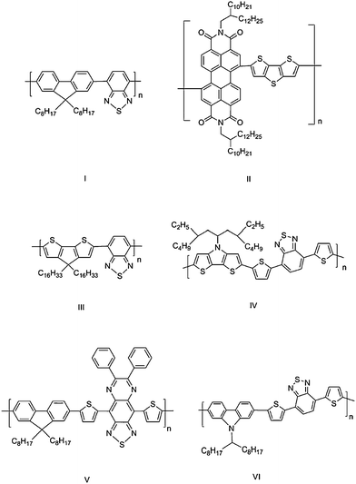 | ||
| Fig. 1 Some polymers discussed in the text. | ||
In recent years, fused thiophene derivatives have been incorporated into the backbones of a variety of conjugated polymers.7–9,19 It has been suggested that rigid fused-ring units can enhance the π–π stacking intermolecular interactions and lead to higher charge-carrier mobilities.20 In addition, planarization of part of the polymer chain, relative to that of a polythiophene, leads to a reduced bandgap; for example, poly(5,5-dialkylcyclopenta[2,1-b:3,4-b′]dithiophene)s show solution absorption maxima at ca. 578 nm,21 while poly(3-alkylthiophene)s typically absorb in the 428–460 nm range.22 Moreover, these building blocks tend to be stronger electron donors than comparable non-fused species, suggesting the possibility of lower-energy charge-transfer-type absorptions in D–A systems. Thus, for example, a bis(dithienothiophene)-substituted perylene diimide small molecule shows a charge-transfer-type band red-shifted from that seen in its bis(bithiophene)-substituted analogue.23,24 Several D–A polymers based on fused-ring donors have been reported and exhibit a range of properties depending on the choice of D and A. For example, a perylene diimide/dithienothiophene copolymer (polymer II) was found to be an electron-transport material with an electron mobility of 1.3 × 10⁻² cm2/(Vs), while a cyclopentadithiophene/benzothiadiazole copolymer (polymer III) was found to be a hole-transport material with a hole mobility of 0.11 cm2/(Vs).7 Polymer II and related compounds have also been used as electron-transport materials in single-layer bulk heterojunction solar cells with efficiencies of up to 1.5% being obtained in conjunction with polythiophene-based hole-transport materials,8,9,25 while branched-alkyl derivatives of III and its benzoselenadiazole analogue have been used as hole-transport components of OPV cells (with efficiencies as high as 3.2%) in conjunction with fullerene acceptors.26–28
More recently, N-alkyl and N-aryl dithieno[3,2-b:2′,3′-d]pyrroles (DTPs) have been incorporated into conjugated oligomers and polymers,19,25,29,30 with OFET hole mobilities of up to 0.21 cm2/(Vs) for DTP-thiophene copolymers, suggesting that this group is a promising building block for hole-transport materials.19 The N-substituents of DTP groups can potentially help improve solubility without interfering with the planarity of this unit relative to the other components of the polymer backbone. DTP-based compounds have been shown to be more easily oxidized than analogous bithiophene and dithienothiophene compounds,31 suggesting that this moiety will act as a strong π-donor when incorporated into D–A polymers.
The acceptor building blocks that we examine in this study, [2,1,3]-benzothiadiazole (BTD), [1,2,5]-thiadiazolo[3,4-g]quinoxaline (TQ) and benzo[1,2-c;4,5-c′]bis[1,2,5]thiadiazole (BBT), have previously been incorporated into various D–A conjugated oligomers and polymers. Polymers based on [2,1,3]-benzothiadiazole copolymerized with thiophene, fluorene, silafluorene, carbazole, cyclopentadithiophene, and dithienosilole groups have been reported; photovoltaic devices made from blends with soluble fullerenes show power conversion efficiencies ranging from 0.2 to 5.4%.10–12,26,27 For example, power conversion efficiencies up to 2.8% were reported for solar cells based on blends of a DTP-BThBTD polymer IV or DTP-BTD copolymers with PCBM.32,33 [1,2,5]Thiadiazolo[3,4-g]quinoxaline derivatives have been used in a variety of D–A copolymers,13,14 including a fluorene-based D–A copolymer (polymer V) shown to have a hole mobility of 0.03 cm2/(Vs) in an OFET.14 Although there are a few reports on the synthesis of oligomers and polymers incorporating BBT,10,16,17 their use in device applications has not been extensively explored.
Recently, we have reported the synthesis of a polymer in which the N-(3,4,5-tri-n-decyloxyphenyl) DTP donor and BBT acceptor are linked by thienylene bridging groups (P3 in Scheme 1). This polymer has an especially low bandgap of ca. 0.5 eV and can be used as the active channel of amibipolar OFETs exhibiting comparable hole and electron mobilities.18 Here we report more fully on this polymer as part of a joint experimental and quantum-chemical study of a series of D–A copolymers; we compare the optical and electronic properties and OPV and OFET performance of P3 with those of analogues incorporating BTD and TQ acceptors (P1 and P2, respectively).
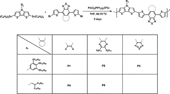 | ||
| Scheme 1 Synthesis of P1–5. | ||
Results and discussion
Synthesis
We have synthesized five polymers incorporating DTP-based donors and BTD-based acceptors: the copolymers P1–5 were prepared by a standard Stille coupling polymerization of N-(3,4,5-tri-n-decyloxyphenyl) or N-(2-decyltetradecyl)-2,6-bis(tri-n-butylstannyl)-dithieno[3,2-b:2′,3′-d]pyrrole with three different di(bromothienyl)-substituted acceptor derivatives (Scheme 1). The polymerizations were carried out in THF at reflux over approximately two days, and the polymers were isolated by reduction of the solvent volume, followed by precipitation into methanol. In each case, the crude polymer was then purified by Soxhlet extraction with methanol, hexane, acetone, and chloroform. The chloroform fraction was then reduced in volume, precipitated into methanol, and collected by filtration, yielding a black solid.The distannyl precursors were obtained by dilithiation of the appropriate parent DTP, followed by treatment with nBu3SnCl. Although distannyl DTP derivatives have been used in previously reported polymerizations, only the bis(trimethylsilyl) derivative used in the synthesis of IV has been isolated,32 and 2,6-di(tri-n-butylstannyl)-N-n-octyl-dithieno[3,2-b:2′,3′-d]pyrrole is reported to be insufficiently stable to permit isolation.30 However, we have found that several di(tri-n-butylstannyl) DTPs, including the present examples and the N-n-dodecyl derivative,25 can be obtained analytically pure after silica gel chromatography. The acceptor monomers were synthesized using reported procedures or known procedures for close analogues.16,17
The copolymers are readily soluble in many common organic solvents including THF, chloroform, and toluene. Weight-average molecular weights (Mw) and polydispersities (Mw/Mn) were estimated by gel-permeation chromatography (GPC) against polystyrene standards using THF as eluent (Table 1). The Mw values for the copolymers vary from 10 kDa to 147 kDa, where all are expected to exhibit optoelectronic and redox properties in the polymer limit. In particular, P1 has a relatively high Mw and low polydispersity compared to a recently reported structurally similar copolymer (polymer IV in Fig. 1) also synthesized using Stille chemistry.32 This is perhaps attributable to improved solubility arising from use of the long-chain alkoxy substituents on the DTP moiety, although we have found that the degree of polymerization is highly sensitive to the monomer purity and the reaction conditions, as would be expected for a condensation polymerization.
| M w (kDa) | M w/Mna | T d (°C)b | |
|---|---|---|---|
| a Weight average molecular weight (Mw) and polydispersity index (Mw/Mn) determined by GPC with THF as eluent vs. polystyrene standards. b Temperature at which 5% weight loss is observed using TGA under N2 at a heating rate of 10 °C/min. c Chromatogram was obtained after multiple purifications using a size-exclusion column and showed a broad bimodal distribution pattern. | |||
| P1 | 147 | 1.4 | 368 |
| P2 | 28 | 2.9 | 367 |
| P3 | 51 | 3.6 | 331 |
| P4 | 22 | 4.0c | 341 |
| P5 | 10 | 2.1 | 351 |
The thermal stabilities of all of the polymers were determined by thermal gravimetric analysis (TGA), as shown in Table 1 and Fig. S1.† Copolymers P1–5 showed good thermal stability with 5% weight loss occurring only at temperatures in excess of 300 °C. Other small weight loss events were observed at ca. 175 °C for P3 and 225 °C for P4 and may be attributable to the presence of small quantities of low molecular weight oligomers, which would be consistent with the relatively high polydispersities (3.6 for P3 and 4.0 for P4) found for those two materials.
Density functional theory electronic structure calculations
The geometries of model oligomers H(DTP-BThX)nH (X = BTD, TQ, BBT, n = 1, 2, and 3) in which the dodecyloxy groups of the DTP N-aryl substituents of P1–P3 are replaced with methoxy groups, and in which the n-hexyl acceptor substituents on the acceptor of P2 were replaced with hydrogen atoms, were minimized at the density functional theory B3LYP/3-21G* level. The energy gaps between highest occupied and lowest unoccupied molecular orbitals, Eg, and the energies of the lowest lying singlet excited states, S1, were computed at B3LYP/6-31G** and INDO/S levels, respectively. Values of Eg and the S1 energy for the polymers were estimated by extrapolation of plots of the calculated parameters for the oligomers vs. 1/n to n = ∞. The HOMO and LUMO wavefunctions of the oligomers H(DTP-BThX)2H are illustrated in Fig. 2. As in several similar polymers with alternating donor and acceptor units,14,32,34 the HOMO wavefunction is delocalized over the entire conjugated backbone, while the LUMO wavefunction is strongly localized on the acceptor units. The extrapolated computational values of the HOMO and LUMO orbital energies, Eg, and S1 are summarized in Table 2. The calculated LUMO energies and band gaps strongly decrease in the order BTD > TQ > BBT, as expected since the acceptor strengths increase in the order BTD < TQ < BBT. In contrast, the HOMO energies are more-or-less independent of the identity of the acceptor. The trends in the calculated HOMO and LUMO energies are consistent with those suggested by the electrochemical oxidation and reduction potentials (see below). In addition, the calculated band gaps for P1–3 (Table 2) are in good agreement with experimental estimates, obtained from either absorption edges or electrochemical measurements (see below, Table 3).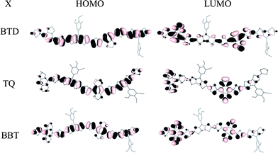 | ||
| Fig. 2 HOMOs and LUMOs of oligomeric derivatives H(DTP-BThX)nH (n = 2). | ||
Optical and electrochemical properties
Optical absorption spectra normalized to the long wavelength peaks in the two-band spectra of the copolymers in dilute THF solution and thin films are shown in Fig. 3 and S2,† respectively, and the corresponding absorption maxima are summarized in Table 3. All the copolymers show two prominent absorption bands: a band in the 470–520 nm range is relatively insensitive to the acceptor strength, while a lower energy band is strongly dependent on the acceptor. The N-alkyl DTP polymers P4 and P5 have similar absorption maxima to their N-aryl DTP analogues, P1 and P2, respectively; slight blue-shifts in the alkyl derivatives are perhaps attributable to their lower Mw values. The lowest energy bands presumably involve considerable donor-to-acceptor charge-transfer (CT) character and, accordingly, the energies of these bands are strongly dependent on the acceptor strength. In thin films, the absorption spectra of the copolymers are similar to those in solution, with slight red-shifts observed in some cases (see Fig. S2†). The absorption maximum in solution obtained for P1 (674 nm) is similar to that of the recently reported closely analogous polymer IV (Fig. 1, λmaxabs at 671 nm);32 however, this absorption maximum is at much lower energy than those obtained for other structurally similar D–A copolymers with donors including carbazole (polymer VI in Fig. 1, λmaxabs at ca. 550 nm) and thiophene or bithiophene (λmaxabs at 435–479 nm),5,16 consistent with the expectation that DTP acts as a stronger donor. Similar observations are seen for P2 or P3 compared with the other D–A copolymers containing the same or similar acceptor moieties. For examples, polymer V absorbs at 840 nm (λmaxabs of P2 at 931 nm)14 and copolymers of BThBBT with thiophene or bithiophene have absorption maxima at 770 and 902 nm respectively (λmaxabs of P3 at 1154 nm).16| Polymer | λmaxabs/nm | E g (optical) eV | E ox onset (DPV) V | IPc (DPV) eV | E red onset (DPV) V | EAc (DPV) eV | E g (DPV) eV | |
|---|---|---|---|---|---|---|---|---|
| Solution | Film | |||||||
| a Values are optical bandgaps estimated from onset absorption edge in solution. b Measured in 0.1 M [nBu4N]+[ClO4]−/propylene carbonate (P1–P3) or 0.1 M [nBu4N]+[PF6]−/acetonitrile (P4–P5) solution and reported vs. SCE.37 c Values were estimated based on IP = Eoxonset + 4.4 eV, EA = Eredonset + 4.4 eV.35,36 | ||||||||
| P1 | 472, 674 | 470, 674 | 1.41 | 0.49 | 4.9 | −1.19 | 3.2 | 1.7 |
| P2 | 508, 931 | 510, 940 | 0.87 | 0.45 | 4.9 | −0.70 | 3.7 | 1.2 |
| P3 | 516, 1154 | 517, 1160 | 0.56 | 0.26 | 4.7 | −0.39 | 4.0 | 0.7 |
| P4 | 457, 646 | 459, 668 | 1.41 | 0.40 | 4.8 | −1.06 | 3.4 | 1.5 |
| P5 | 493, 919 | 495, 948 | 0.92 | 0.39 | 4.8 | −0.74 | 3.7 | 1.1 |
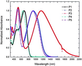 | ||
| Fig. 3 UV-vis-NIR spectra of copolymers P1–5 in THF. | ||
The electrochemical properties of the polymers were characterized by differential pulse voltammetry (DPV) using films of the polymers drop-cast onto a platinum button working electrode in a 0.1 M tetrabutylammonium perchlorate ([nBu4N]+[ClO4]−)/propylene carbonate solution (for P1–3) or tetrabutylammonium hexafluorophosphate ([nBu4N]+[PF6]−)/acetonitrile solution (for P4–5) and are summarized in Table 3. The oxidative and reductive DPV of P1–3 are shown in Fig. 4 (data for P4 and P5 are shown in Fig. S3†). The electrochemical oxidation and reduction onsets (Eoxonset and Eredonsetvs. SCE) were also used to obtain estimates of solid-state ionization potential (IP) and electron affinity (EA) according to IP = Eoxonset + 4.4 eV, EA = Eredonset + 4.4 eV; the electrochemical band gaps were obtained from the difference between the Eoxonset and Eredonset.35,36 The oxidation potentials show relatively little variation with the choice of acceptor and of DTP N-substituent, although P3 appears to be slightly more easily oxidized. The estimated values of ionization potentials in these polymers (4.7–4.9 eV) are similar to those obtained in electrochemical estimates for other DTP-containing polymers (4.7–5.0 eV),19,32,33 although a detailed direct comparison is not possible due to the use of different electrochemical methods in different studies (DPV vs. CV, onset vs. peak potentials, varying scan rates). On the other hand, the reduction potentials change significantly when the acceptors in the polymer backbone were varied, while being more-or-less unaffected by the N-substituents of the DTP units. The trends mirror those obtained for small molecules related to the present monomers; solution CV peak reduction potentials of −1.22, −0.72 and −0.53 V vs. SCE have been reported for BThX, X = BTD, TQ and BBT, respectively.17 The increase in ease of reduction from P1 to P2 to P3 is also consistent with the trends of red-shifts in their low-energy CT-type bands, and provides further evidence for the increase of electron-accepting strengths in the order BTD < TQ < BBT.
 | ||
| Fig. 4 DPV of P1–3 (a–c) on a Pt button working electrode with a step size of 2 mV and step time of 0.1 second. | ||
The optical and electrochemical data are generally in good agreement with the calculations described in the previous section. Experimental electrochemical and optical bandgaps are similar in magnitude to the respective DFT-extrapolated bandgaps and S1 energies (Table 2) and show the same trends. The experimental sensitivity of the low-energy absorption to the acceptor is consistent with the molecular orbitals shown in Fig. 2, in which the LUMOs are strongly acceptor-localized, indicating that a HOMO–LUMO transition would have substantial DTP-to-acceptor CT character. The variation of the reduction potentials with acceptor, and the relative invariance of the oxidation potentials, are also consistent with the trends in calculated orbital energies. The optical and electronic properties of the polymers suggest some possible applications: the broad low-energy absorption bands suggest use in OPVs and photodetectors, while the estimated IP and EA values suggest the possibility of facile injection of both holes and electrons from commonly used electrode materials, which is a prerequisite for use as ambipolar charge-transport materials. The ease of oxidation and reduction also suggests possible use in electrochromic applications if the redox processes are associated with appropriate spectroscopic changes; we now turn to examine these electrochromic properties.
Spectroelectrochemistry
Spectroelectrochemical measurements offer a direct means of evaluating the electrochromic properties of the materials35,38,39 and were performed on films of P1–P3. All three polymers undergo similar spectral changes on oxidation; the oxidative spectra of P1 are shown in Fig. 5a, while those of P2 and P3 are shown in Fig. S4.† As described above, the neutral states of all the copolymers show two peaks, one at 470–520 nm and another in the low-energy portion of the visible or in near-IR, with the appearance of neutral P1–P3 varying from green to dark pink to purple (see photographs in Table 4). Upon incremental oxidation of P1, there is a bleaching of both neutral peaks (473 nm and 660 nm) with concomitant formation of charge carrier peaks around 800 nm and beyond 1600 nm in the near-IR. Upon full oxidation, the charge carrier band beyond 1600 nm tails through the visible portion of the spectrum resulting in a more visibly transparent gray/blue film.| P1 | P2 | P3 | |
|---|---|---|---|
| Ox |

|

|

|
| Neut |

|

|

|
| Red 1 |

|

|

|
| Red 2 |

|

|
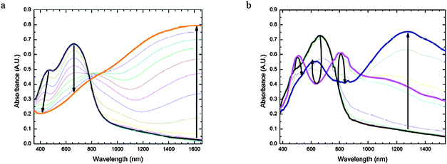 | ||
| Fig. 5 Spectroelectrochemistry of P1. a (left) Oxidative spectroelectrochemistry of P1 spray-cast onto ITO from −0.16 V to 1.24 V vs. SCE in 100 mV increments. Bold black line = neutral (−0.16 V) and bold orange line = oxidized state (1.24 V); b (right) Reductive spectroelectrochemistry of P1 spray-cast onto ITO, from −0.92 V to −1.72 V vs. SCE in 100 mV increments. Bold black line = neutral (−0.92 V), bold pink line = beginning of intermediate reduced state (−1.42 V), and bold navy blue line = fully reduced state (−1.72 V). | ||
In the reductive spectroelectrochemistry of the three copolymers (Fig. 5b and S5†) there are slight differences between that of P1 and those for P2 and P3. In P1, even when the potential was stepped to −1.7 V vs. SCE, only one reduced state could be accessed, whereas P2 and P3 show successive formation of two different reduced states; this is qualitatively consistent with the weaker electron-accepting strength of the BTD moiety compared to the other two acceptors (TQ and BBT). During incremental reduction of P1 (Fig. 5b) there is a sharp decrease in the low-energy absorption at 660 nm at intermediate reduction potentials (−1.32 to −1.52 V), along with the formation of bands at 500 nm and 810 nm tailing further into the near-IR. Upon complete reduction, there is an intense lower energy transition that develops at ca. 1280 nm and a smaller peak at ca. 625 nm and the film appears light purple. In P2 and P3 incremental potential stepping from the neutral state to the first reduced state induces a decrease in intensity of the near-IR bands of the neutral polymers along with the formation of a band at even longer wavelength (ca. 1300 nm in P2, ca. 1500 nm in P3). There is a concomitant increase in the intensity of the high-energy band at ca. 520 nm (with a 10–15 nm red shift) along with the development of a shoulder at ca. 700 nm. This results in a darker purple film in the first reduced state. When the potential is stepped to the second reduction, the band at ca. 1500 nm is fully bleached, while the shoulder from the first reduction develops into new peaks between 800–900 nm. This results in the polymers yielding a bright blue/purple film with saturated color. The loss of the long-wavelength band (ca. 1300 nm in P2 and ca. 1500 nm in P3) suggests that the reduction results in a negative charge isolated on the acceptor, thereby precluding an ICT band.
The spectroelectrochemical measurements indicate that each of the three polymers can be either p-doped or n-doped at moderate potentials, with three or four differently colored redox states being accessible in each case (Table 4). Studies to further exploit these properties are in progress.
Field-effect transistor characteristics
Charge-carrier transport in the copolymers was explored directly by investigating their use as the active layer in top-contact organic field-effect transistors (OFETs) fabricated with gold source/drain electrodes and SiO2 treated with octadecyl-trichlorosilane (OTS) as a gate dielectric layer. Field-effect mobilities (µ) and threshold voltages (VT) were measured in the saturation regime from the saturation region current equation for a standard MOSFET, using the highest slope of the |IDS|1/2vs.VGS plot:where Ci is the capacitance per unit area of the gate dielectric [F/cm2], and W (width) and L (length) are the dimensions of the semiconductor channel defined by the source and drain electrodes of the transistor. Characteristics of OFETs based on copolymers P1–3, including mobilities (µ), threshold voltages (VT), and current on/off ratios (Ion/Ioff), are summarized in Table 5.
| Polymer | Operation mode | µ (cm2/(Vs)) | V T (V) | I on/Ioff |
|---|---|---|---|---|
| P1 | p-type | 1.2 × 10⁻⁴ | 2.2 | 102–103 |
| P2 | p-type | 2.2 × 10⁻³ | −8.2 | 103–104 |
| P3 | p-type | 1.6 × 10⁻³ | −16 | — |
| P3 | n-type | 7.9 × 10⁻⁴ | 37.4 | — |
| P4 | p-type | 1.6 × 10⁻⁴ | −10.6 | 2 × 10² |
| P5 | p-type | 2.6 × 10⁻³ | −17.4 | 104 |
Fig. 6 and 7 show the output and transfer characteristics of OFETs (W/L = 1000 µm/100 µm) based on P1 and P2 (data for P4 and P5 are given in Fig. S6 and S7†). The devices based on P1, P2, P4 and P5 all showed typical p-channel field-effect transistor characteristics. Devices with P1 or P4 exhibited hole mobilities of about 10−4 cm2/(Vs) with current on/off ratios around 102–103. These relatively low current on-off ratios might be due to adventitious doping since the materials are easily oxidized; indeed such doping has been suggested to result in low on/off ratios in other low-IP DTP materials.19 OFETs based on P2 or P5 show higher p-channel average hole mobility values of about 10−3 cm2/(Vs) along with improved current on/off ratios of about 103–104. It was also found that annealing could lead to improved device performance; for instance, the average hole mobility values of the devices of P2 before and after post-annealing were 1.2 × 10⁻³ and 2.2 × 10⁻³ cm2/(Vs), respectively. Comparison of the OFET results for P1 and P4, and of those for P2 and P5, suggests that the N-substituents on the DTP donors do not significantly influence the charge-carrier transporting properties of the polymers.
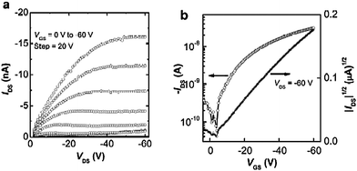 | ||
| Fig. 6 Output (a) and transfer (b) characteristics of an OFET based on P1. | ||
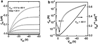 | ||
| Fig. 7 Output (a) and transfer (b) characteristics of an OFET based on P2. | ||
Since quantum-chemical calculations, electrochemistry, and spectroelectrochemistry suggest the possibility of both hole and electron injection into P3 at moderate potentials, it was thought that this polymer might serve as an ambipolar charge-transport material. Fig. 8 shows the output characteristics of an OFET (W/L = 1000 µm/100 µm) in which P3 is the active material and in which the source and drain electrodes are Au. These OFETs show ambipolar behavior with the hole and electron mobilities of similar magnitude, 1.6 × 10⁻³ cm2/(Vs) and 7.9 × 10⁻⁴ cm2/(Vs) for p- and n-channel, respectively. Those values are slightly higher than those we reported previously (1.2 × 10⁻³ cm2/(Vs) and 5.8 × 10⁻⁴ cm2/(Vs) for p- and n-channel) when using Al source and drain electrodes.18 Few low band-gap polymers have been used in the fabrication of ambipolar OFETs,6,40 and the obtained hole and electron mobilities have been of similar magnitude to those reported here. Although the hole and electron mobilities obtained in P3 are moderate, this polymer is one of very few examples of materials that have been found to exhibit ambipolar characteristics in OFETs processed from solution.
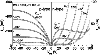 | ||
| Fig. 8 Output characteristics (p-type and n-type) of an OFET based on P3. | ||
Photovoltaic cell characteristics
Bulk heterojunction photovoltaic devices were fabricated based on blends of each polymer with the soluble fullerene, PCBM. The J–V characteristics of the devices based on P1–3 are shown in Fig. 9 (data for P4/PCBM are shown in Fig. S8†); the performance of devices based on the different polymers and, in the case of P1, fabricated under different conditions is summarized in Table 6.| Polymer (polymer : PCBM weight ratio) | Spin-coating solventc | V OC (mV) | J SC (mA/cm2) | FF | Efficiency (η) (%) |
|---|---|---|---|---|---|
| a A 1:1 P5/PCBM device from chlorobenzene exhibited no measurable photocurrent. b Measured with a broadband xenon lamp (ASB-XE-175EX, CVI), 75 mW/cm2. c Abbreviations for solvents: CB = chlorobenzene, OXY = o-xylene, DCB = 1,2-dichlorobenzene, TOL = toluene. | |||||
| P1 (1:1) | CB | 500 ± 4 | 4.3 ± 0.1 | 0.37 ± 0.01 | 1.1 ± 0.1 |
| P1 (1:2) | CB | 511 ± 6 | 4.1 ± 0.1 | 0.43 ± 0.01 | 1.2 ± 0.1 |
| P1 (1:3) | CB | 510 ± 2 | 3.9 ± 0.2 | 0.47 ± 0.01 | 1.3 ± 0.1 |
| P1 (1:3) | OXY | 523 ± 2 | 3.6 ± 0.1 | 0.39 ± 0.01 | 0.9 ± 0.1 |
| P1 (1:3) | DCB | 436 ± 4 | 1.7 ± 0.2 | 0.54 ± 0.01 | 0.56 ± 0.08 |
| P1 (1:3) | TOL | 394 ± 48 | 1.6 ± 0.4 | 0.25 ± 0.01 | 0.19 ± 0.07 |
| P2 (1:1) | CB | 268 ± 3 | 1.7 ± 0.1 | 0.36 ± 0.01 | 0.22 ± 0.01 |
| P3 (1:1) | CB | 109 ± 4 | 0.20 ± 0.01 | 0.29 ± 0.01 | 0.007 ± 0.001 |
| P4 (1:1) | CB | 299 ± 22 | 1.2 ± 0.1 | 0.33 ± 0.01 | 0.17 ± 0.02 |
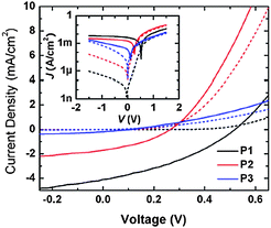 | ||
| Fig. 9 J–V characteristics of multiple cells measured in the dark (dashed line) and under illumination (solid line) for films of PCBM blended with P1 (black), P2 (red), or P3 (blue) in a 1:1 weight ratio. Inset shows the same data in a semilogarithmic plot. | ||
Based on the optical and OFET data for P1 and P4 described in the previous sections, the BTD-based polymers have good spectral coverage of the visible spectrum and reasonable hole mobility. Moreover, the estimated IPs and EAs suggest that the BTD polymers P1 and P4 offer the best energy-level alignment with PCBM of the five copolymers; the estimated EAs of these polymers (ca. 3.2–3.4 eV) are 0.5–0.7 eV lower in magnitude than that of PCBM (3.9 eV),41 an offset which the literature suggests should be sufficient for achieving high charge-separation yields in a blend.42,43 Therefore, they were thought to be good candidates for a donor in photovoltaic applications in combination with fullerene acceptors. Indeed, in preliminary studies, cells in which 1:1 blends of PCBM and P1 were processed from chlorobenzene exhibited higher efficiencies than cells fabricated with the other copolymers. Some studies on bulk-heterojunction solar cells fabricated from conjugated polymers and fullerenes have suggested that different weight ratios of the polymers to PCBM as well as solvents can affect the nanoscale morphology of the films.44 Optimizations of the devices of P1 blended with PCBM were carried out by varying the weight ratio of polymer and PCBM and/or changing the processing. The best performance was observed when the polymer was spin-coated using chlorobenzene and blended with PCBM in a 1:3 weight ratio; this device showed a power conversion efficiency, η, under broadband light, of 1.3 ± 0.1%.
Devices with P2, P3, P4, and P5 were also fabricated and measured using the same methods. Of the polymers incorporating the N-aryl-DTP donor, the lowest photocurrent coupled with the smallest open-circuit voltage led to the lowest power conversion efficiency in devices based on P3. The devices incorporating P2, the estimated EA of which lies between that of P1 and P3, gave photovoltaic performance intermediate between that of P1 and P3. Nevertheless, the similarity of the estimated EA of 3.7 eV in P2 (or 4.0 eV in P3) and 3.9 eV in PCBM,41 might be one of the reasons for low efficiency since a driving force of 0.3–0.5 eV is generally required to achieve efficient exciton dissociation and charge separation.42,43 Cells based on the two N-alkyl-DTP polymers P4 and P5 were considerably less efficient than those based on their respective N-aryl analogues, despite the choice of N-substituent having rather small effects on electrochemical and optical properties and on the mobility. The poor OPV performance of P4 and P5 may perhaps in part be related to the relatively low solubility of these polymers in chlorobenzene.
The external quantum efficiency (EQE) spectrum for a P1 device with PCBM in a 1:1 weight ratio is shown in Fig. 10 and indicates that there is absorption of photons and conversion into current out to wavelengths of ∼800 nm. While the broad spectrum is encouraging, photocurrent is limited by the maximum EQE of ∼30%. From the EQE, the AM1.5 G efficiency for this device is estimated to be ∼0.9%.
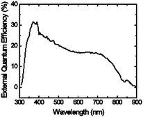 | ||
| Fig. 10 External quantum efficiency (EQE) as a function of wavelength of a device made from a blend of P1/PCBM (1:1 w:w). | ||
Although our efficiencies on solar cells based on P1 are not as high as those reported for devices based upon the structurally similar copolymer IV (Fig. 1),16 the optimization of the devices by varying the weight ratio with PCBM, as well as changing the solvents, could provide useful information for further studies of the photovoltaic applications of DTP-based copolymers. To gain more insight into the variations in the dependence of the photovoltaic behaviour on the blend compositions and processing solvents, atomic force microscopy (AFM) images of the blends have been obtained and compared. The height images (Fig. 11) of the blends of P1/PCBM (1:3) films fabricated from chlorobenzene, toluene, and o-xylene show that the film fabricated from chlorobenzene gave the morphology with the smoothest surface and smallest domain size. The root mean square roughness values for P1/PCBM (1:3 weight ratio) films processed from chlorobenzene, o-xylene, and toluene are 1.3, 3.5 and 12.7 nm, respectively. Our observation of different morphologies when processed from different solvents is somewhat similar to what has been observed and reported in the literature on processing other polymer blends with PCBM from different solvents.25
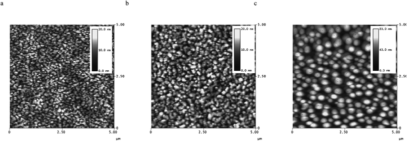 | ||
| Fig. 11 AFM tapping-mode height images of P1/PCBM (1:3 weight ratio) film surface processed from a) chlorobenzene, b) o-xylene and c) toluene. The vertical gray scale is 20 nm for a) and b) and 80 nm for c). | ||
Although the photovoltaic cell performance of P1/PCBM devices is moderate, and the performances of devices based on P2 and P3 are relatively low, optimizations of P1-based devices revealed the effects of donor/acceptor ratio and of different processing solvents. Device performance might be further improved by annealing and/or control of the film morphology. Moreover, devices based on P2 and P3 might be useful as active components in tandem cells due to their broad absorbance in the near-IR range, especially if other layers of the cells are judiciously chosen to have complementary absorption spectra, i.e., to have strong absorption at ca. 600–700 nm, where the spectra of P2 and P3 exhibit minima. Moreover, they may also potentially serve as near-IR photodetectors.
Conclusions
We have synthesized and characterized a series of D–A copolymers based on N-aryl and N-alkyl dithieno[3,2-b:2′,3′-d]pyrrole donors linked through thienylene bridges to benzothiadiazole-based acceptors. Quantum-chemical calculations along with the optical and electrochemical properties of these copolymers suggest that the HOMO energy is only weakly dependent upon the choice of the acceptors, while the LUMO energy and the energy of the low-energy absorption band is strongly influenced by the acceptor. Both theory and experiment indicate that the acceptor strength increases in the order benzothiadiazole < thiadiazolo[3,4-g]quinoxaline < benzobisthiadiazole. The low-energy absorption bands have considerable donor-to-acceptor charge-transfer character and, in the case of the compound with a benzobisthiadiazole acceptor, this band is found at ca. 1.2 µm. To our knowledge, this material is the lowest bandgap solution-processable polymer. Furthermore, their potential utilities in electrochromic devices, OFETs, and OPVs were tested. Spectroelectrochemical measurements indicated they can be either electrochemically p-doped or n-doped at moderate potentials, suggesting that the polymers could have potential use in electrochromic devices. Four of the polymers functioned as hole-transport materials in OFETs with mobilities as high as 2.2 × 10⁻³ cm2/(Vs), while the example with the strongest acceptor exhibited ambipolar field-effect characteristics. In the OPV devices made from the N-aryl DTP copolymer/PCBM blends, the example with the weakest acceptor (benzothiadiazole) exhibited the best performance with a power conversion efficiency up to 1.3 ± 0.1%. Devices based on the other acceptors exhibit significantly lower efficiencies, presumably in part due to reduced driving force for charge-transfer to PCBM; however, they might act as active components in tandem cells due to their broad absorbance in the near-IR, especially in conjunction with more electron-accepting electron-transport materials than PCBM. In summary, the present study demonstrated that optical and electronic properties of this series of D–A copolymers can be easily manipulated through the acceptor strength, and also resulted in their potential uses in various applications, such as electrochromic devices, OFETs and OPVs.Experimental
Materials
Unless stated otherwise, starting materials were purchased and were used without further purification. The synthesis of 2,6-bis(tri-n-butylstannyl)-N-(3,4,5-tris(n-dodecyloxy)phenyl)-dithieno[3,2-b:2′,3′-d]pyrrole and P3 was reported in our previous communication.18 4,7-Bis(5-bromothien-2-yl)-[2,1,3]-benzothiadiazole, 4,7-bis(5-bromothien-2-yl)-2λ4δ2-benzo[1,2-c;4,5-c′]bis[1,2,5]thiadiazole16 and 6,7-di(n-hexyl)-4,9-di(thien-2-yl)-[1,2,5]thiadiazolo[3,4-g]quinoxaline17 were prepared according to the published procedures.Characterization
The 1H and 13C NMR spectra were measured on a Varian Mercury 300 MHz spectrometer. Mass spectra were measured on an Applied Biosystems 4700 Proteomics Analyzer using MALDI mode. Elemental analyses were carried out by Atlantic Microlabs using a LECO 932 CHNS elemental analyzer. UV-Vis absorption spectra were recorded on a Varian Cary 500 UV-Vis-NIR spectrophotometer. Electrochemistry and spectroelectrochemistry were performed in a three-electrode cell consisting of an ITO-coated glass or platinum button working electrode, a platinum wire/flag counter electrode, and a Ag/Ag+ reference electrode or a silver wire pseudo-reference electrode in a 0.1 M [nBu4N]+[ClO4]−/propylene carbonate or 0.1 M [nBu4N]+[PF6]−/acetonitrile solution calibrated using the ferrocene-ferrocenium redox couple, assuming the values of [FeCp2]+/0 = 0.34 V (for 0.1 M [nBu4N]+[ClO4]−/propylene carbonate solution) or 0.40 V (0.1 M [nBu4N]+[PF6]−/acetonitrile solution) vs. SCE.37 Polymer films were spray cast onto ITO-coated glass working electrodes or drop cast onto platinum button (0.02 cm2) working electrodes from a chloroform solution. Electrochemical measurements were made with an EG&G PAR model 273A potentiostat/galvanostat or BAS 100B electrochemical analyzer, and optical data were measured with a Cary 500 UV-Vis-NIR spectrophotometer or a StellerNet Diode Array UV-Vis-NIR. Thermal gravimetric analysis (TGA) measurements were performed on a NETZSCH thermogravimetric analyzer (model STA 449C) under a nitrogen flow at a heating rate of 10 °C/min. Gel permeation chromatography (GPC) was performed using a Waters Associates GPCV2000 liquid chromatography system with its internal differential refractive index detector (DRI) at 40 °C, using two Waters Styragel HR-5E columns (10 µm PD, 7.8 mm i.d., 300 mm length) with HPLC grade THF as the mobile phase at a flow rate of 1.0 mL/min. Injections were made at 0.05–0.07% w/v sample concentration using a 220.5 µL injection volume. Retention times were calibrated against a minimum of nine narrow molecular weight polystyrene standards (Polymer Laboratories; Amherst, MA).Fabrication and characterization of thin film transistors
OFETs were fabricated on heavily n-doped silicon substrates (also serving as the gate electrodes) with 200 nm thick thermally grown SiO2 as the gate dielectric in top contact configuration. Ti/Au (10 nm/100 nm) metallization on the backside of the substrate was done to enhance the gate electrical contact. OTS treatment (with 5mM in toluene) was carried out by soaking the substrates in the OTS solution for 15 h in a N2-filled dry box. The substrates were rinsed with toluene and annealed at 60 °C for 5 minutes. The capacitance of the OTS treated SiO2 was 16.2 nF/cm2. A thin layer of organic semiconductor was formed on the substrates by spin coating with a solution (10–20 mg/mL) in chlorobenzene. To remove the solvent from the film, a pre-annealing was performed at 90 °C for 30 min. Au (50 nm thickness) was deposited through a shadow mask to act as top source and drain electrodes. The prepared devices were post-annealed at 130 °C for 35 min (followed by 150 °C for 30 min for P3) inside another N2 glove box with an I–V characterization setup.Fabrication and characterization of photovoltaic cells
Photovoltaic cells were fabricated by blending one of the three copolymers with the acceptor 3′-phenyl-3′H-cyclopropa[1,9](C60-Ih)[5,6]fullerene-3′-butanoic acid methyl ester (PCBM) (MTR Ltd.). Solutions of a polymer and PCBM were made in chlorobenzene (1:1 weight ratio, 20 mg/mL) for each of the polymers. ITO-coated glass (Colorado Concept Coatings LLC) with a sheet resistance of ∼15 Ω/sq. was used as the substrate for the solar cells. The substrates were cleaned in an ultrasonic bath of detergent water, rinsed with deionized water, and then cleaned in sequential ultrasonic baths of deionized water, acetone, and isopropanol. Nitrogen was used to dry the substrates after each of the last three baths. A 300 nm thick layer of SiOx was deposited on the cleaned ITO by e-beam deposition (AXXIS, Kurt J. Lesker) to pattern the anode. Next, the substrates were ultrasonicated in isopropanol for 10 min, blown dry with nitrogen, and air-plasma treated for 2 min. A hole-conducting layer of PEDOT:PSS (CLEVIOS P VP AI 4083, H. C. Starck) was filtered through a 0.45 µm pore PVDF filter and spin coated on the substrates at 5000 rpm for 1 min, and the substrates were annealed at 140 °C for 10 min in the atmosphere. After loading into a nitrogen-filled glove box, 80–90 nm thick films of the polymer mixtures were deposited on the substrates by spin coating for 1 min at speeds of 1000 rpm for the mixtures of P3 or P4 with PBCM and 1500 rpm for mixtures of P1 or P2 with PCBM. The solutions were filtered through 0.2 µm pore PTFE filters prior to spin coating (samples containing P2 or P4 easily clogged the filter, so no filter was used). The substrates were then loaded into a vacuum thermal evaporation system (SPECTROS, Kurt J. Lesker) connected to the glove box, and 200 nm of Al was deposited through a shadow mask at a rate of 1–3 Å/s and a base pressure of ∼7 × 10⁻⁸ Torr to define the cathodes. The completed devices were transferred in a sealed container to another nitrogen-filled glove box for electrical measurements. Current–voltage characteristics were measured using a source meter (2400, Keithley) controlled by a LabVIEW program. When testing the solar cells under illumination, filtered light from a 175 W xenon lamp (ASB-XE-175EX, CVI) was used as a broadband light source with an irradiance of 75 mW/cm2 to simulate sunlight. A monochromator and calibrated photodiode were used to measure external quantum efficiency (EQE).Acknowledgements
This work was funded in part by DARPA (N00014-06-1-0897), the Office of Naval Research (at GIT and N00014-08-1-0928), the AFOSR (FA9550-09-1-0320) and the STC Program of the National Science Foundation under Agreement No. DMR-0120967. The solid-state device work was performed in part at the Microelectronics Research Center at Georgia Institute of Technology, a member of the National Nanotechnology Infrastructure Network, which is supported by NSF (Grant No. ECS-03-35765).Notes and references
- A. Facchetti, Mater. Today, 2007, 10, 28 CrossRef CAS
.
- A. Salleo, Mater. Today, 2007, 10, 38 CrossRef CAS
.
- G. Li, V. Shrotriya, Y. Yao, J. S. Huang and Y. Yang, J. Mater. Chem., 2007, 17, 3126 RSC
.
- B. S. Ong, Y. L. Wu, Y. N. Li, P. Liu and H. L. Pan, Chem.–Eur. J., 2008, 14, 4766 CrossRef CAS
.
- N. Blouin, A. Michaud, D. Gendron, S. Wakim, E. Blair, R. Neagu-Plesu, M. Belletete, G. Durocher, Y. Tao and M. Leclerc, J. Am. Chem. Soc., 2008, 130, 732 CrossRef CAS
.
- J. Zaumseil, C. L. Donley, J. S. Kim, R. H. Friend and H. Sirringhaus, Adv. Mater., 2006, 18, 2708 CrossRef CAS
.
- M. Zhang, H. N. Tsao, W. Pisula, C. D. Yang, A. K. Mishra and K. Mullen, J. Am. Chem. Soc., 2007, 129, 3472 CrossRef CAS
.
- I. Osaka, G. Sauve, R. Zhang, T. Kowalewski and R. D. McCullough, Adv. Mater., 2007, 19, 4160 CrossRef CAS
.
- Z. A. Tan, E. J. Zhou, X. W. Zhan, X. Wang, Y. F. Li, S. Barlow and S. R. Marder, Appl. Phys. Lett., 2008, 93, 073309 CrossRef
.
- E. Bundgaard and F. C. Krebs, Sol. Energy Mater. Sol. Cells, 2007, 91, 1019–1025 CrossRef CAS
.
- Q. Hou, Q. M. Zhou, Y. Zhang, W. Yang, R. Q. Yang and Y. Cao, Macromolecules, 2004, 37, 6299–6305 CrossRef CAS
.
- E. G. Wang, L. Wang, L. F. Lan, C. Luo, W. L. Zhuang, J. B. Peng and Y. Cao, Appl. Phys. Lett., 2008, 92, 033307 CrossRef
.
- K.-F. Cheng, C.-C. Chueh, C.-H. Lin and W.-C. Chen, J. Polym. Sci. B, 2008, 46, 6305 CAS
.
- M. X. Chen, X. Crispin, E. Perzon, M. R. Andersson, T. Pullerits, M. Andersson, O. Inganas and M. Berggren, Appl. Phys. Lett., 2005, 87, 252105 CrossRef
.
- J. Hou, S. Zhang, T. L. Chen and Y. Yang, Chem. Commun., 2008, 6034 RSC
.
- E. Bundgaard and F. C. Krebs, Macromolecules, 2006, 39, 2823–2831 CrossRef CAS
.
- C. Kitamura, S. Tanaka and Y. Yamashita, Chem. Mater., 1996, 8, 570 CrossRef
.
- T. T. Steckler, X. Zhang, J. Hwang, R. Honeyager, S. Ohira, X.-H. Zhang, A. Grant, S. Ellinger, S. A. Odom, D. Sweat, D. B. Tanner, A. G. Rinzler, S. Barlow, J.-L. Brédas, B. Kippelen, S. R. Marder and J. R. Reynolds, J. Am. Chem. Soc., 2009, 131, 2824 CrossRef CAS
.
- J. Y. Liu, R. Zhang, G. Sauve, T. Kowalewski and R. D. McCullough, J. Am. Chem. Soc., 2008, 130, 13167 CrossRef CAS
.
- X. N. Zhang, J. P. Johnson, J. W. Kampf and A. J. Matzger, Chem. Mater., 2006, 18, 3470 CrossRef CAS
.
- L. De Cremer, S. Vandeleene, M. Maesen, T. Verbiest and G. Koeckelberghs, Macromolecules, 2008, 41, 591 CrossRef CAS
.
- R. D. McCullough, Adv. Mater., 1998, 10, 93 CrossRef CAS
and references therein.
- J. Huang, H. Fu, Y. Wu, S. Chen, F. Shen, X. Zhao, Y. Liu and J. Yao, J. Phys. Chem. C, 2008, 112, 2689 CrossRef CAS
.
- J. Huang, Y. Wu, H. Fu, X. Zhan, J. Yao, S. Barlow and S. R. Marder, J. Phys. Chem. A, 2009, 113, 5039 CrossRef CAS
.
- X. Zhan, Z. A. Tan, E. Zhou, Y. Li, R. Misra, A. Grant, B. Domercq, X.-H. Zhang, Z. An, X. Zhang, S. Barlow, B. Kippelen and S. R. Marder, J. Mater. Chem., 2009, 19, 5794 RSC
.
- D. Mühlbacher, M. Scharber, M. Morana, Z. Zhu, D. Waller, R. Gaudiana and C. Brabec, Adv. Mater., 2006, 18, 2884 CrossRef
.
- J. Peet, J. Y. Kim, N. E. Coates, W. L. Ma, D. Moses, A. J. Heeger and G. C. Bazan, Nat. Mater., 2007, 6, 497 CrossRef CAS
.
- J. Hou, T. L. Chen, S. Zhang, H.-Y. Chen and Y. Yang, J. Phys. Chem. C, 2009, 113, 1601 CrossRef CAS
.
-
L. U. Lehmann, U.S. Pat. Appl. Publ., 2008, 2008262183
.
- K. R. Radke, K. Ogawa and S. C. Rasmussen, Org. Lett., 2005, 7, 5253 CrossRef CAS
.
- S. A. Odom, K. Lancaster, L. Beverina, K. M. Lefler, N. J. Thompson, V. Coropceanu, J. L. Brédas, S. R. Marder and S. Barlow, Chem.–Eur. J., 2007, 13, 9637 CrossRef CAS
.
- E. J. Zhou, M. Nakamura, T. Nishizawa, Y. Zhang, Q. S. Wei, K. Tajima, C. H. Yang and K. Hashimoto, Macromolecules, 2008, 41, 8302 CrossRef CAS
.
- W. Yue, Y. Zhao, S. Shao, H. Tian, Z. Xie, Y. Geng and F. Wang, J. Mater. Chem., 2009, 19, 2199 RSC
.
- B. P. Karsten, L. Viani, J. Gierschner, J. Cornil and R. A. J. Janssen, J. Phys. Chem. A, 2008, 112, 10764 CrossRef CAS
.
- L. Micaroni, F. C. Nart and I. A. Huemmelgen, J. Solid State Electrochem., 2002, 7, 55 CrossRef CAS
.
- We have previously reported slightly different estimated IP and EA values for P3, the differences being due to different assumptions being used in the estimates. Of course, the trends in the electrochemically estimated IP and EA values for the series of polymers will be the same regardless of the method used to estimate these values.
- N. G. Connelly and W. E. Geiger, Chem. Rev., 1996, 96, 877 CrossRef CAS
.
- B. C. Thompson, Y. G. Kim, T. D. McCarley and J. R. Reynolds, J. Am. Chem. Soc., 2006, 128, 12714 CrossRef CAS
.
- P. M. Beaujuge, S. Ellinger and J. R. Reynolds, Nat. Mater., 2008, 7, 795 CrossRef CAS
.
- T. Yamamoto, T. Yasuda, Y. Sakai, S. Aramaki and A. Ramaw, Macromol. Rapid Commun., 2005, 26, 1214 CrossRef CAS
.
- K. Akaike, K. Kanai, H. Yoshida, J. Tsutsumi, T. Nishi, N. Sato, Y. Ouchi and K. Seki, J. Appl. Phys., 2008, 104, 023710 CrossRef
.
- H. Ohkita, S. Cook, Y. Astuti, W. Duffy, S. Tierney, W. Zhang, M. Heeney, I. McCulloch, J. Nelson, D. D. C. Bradley and J. R. Durrant, J. Am. Chem. Soc., 2008, 130, 3030 CrossRef CAS
.
- M. C. Scharber, D. Wuhlbacher, M. Koppe, P. Denk, C. Waldauf, A. J. Heeger and C. L. Brabec, Adv. Mater., 2006, 18, 789 CrossRef CAS
.
- H. Hoppe, M. Niggemann, C. Winder, J. Kraut, R. Hiesgen, A. Hinsch, D. Meissner and N. S. Sariciftci, Adv. Funct. Mater., 2004, 14, 1005 CrossRef CAS
.
Footnote |
| † Electronic supplementary information (ESI) available: TGA curves of P1–P5, UV-vis-NIR spectra of P1–P5 in thin films, Oxidative spectroelectrochemistry of P2 and P3, Reductive spectroelectrochemistry of P1 and P2, DPV of P4 and P5. See DOI: 10.1039/b915940a |
| This journal is © The Royal Society of Chemistry 2010 |

