Surface-independent vertical orientation of cylindrical microdomains in block copolymer thin films directed by comb-coil architecture
Myungeun
Seo
a,
Seonhee
Shin
a,
Sejin
Ku
a,
Sangwoo
Jin
b,
Jin-Baek
Kim
a,
Moonhor
Ree
b and
Sang Youl
Kim
*a
aDepartment of Chemistry, KAIST, Gwahangno 335, Yuseong-gu, Daejeon, 305-701, Korea. (+82) 42-350-2834. E-mail: kimsy@kaist.ac.kr; Fax: (+82) 42-350-8177
bDepartment of Chemistry, Pohang Accelerator Laboratory, National Research Laboratory for Polymer Synthesis and Physics, Center for Electro-Photo Behaviors in Advanced Molecular Systems, Division of Advanced Materials Science, Polymer Research Institute, and BK School of Molecular Science, Pohang University of Science & Technology, Pohang, 790-784, Korea
First published on 7th October 2009
Abstract
Vertically oriented cylindrical microdomains of block copolymer thin films consisting of polystyrene and poly(methyl methacrylate) were fabricated regardless of the substrate by introduction of a grafted architecture into the diblock copolymer chains. A series of comb-coil block copolymers, poly(methyl methacrylate)-b-poly(2-(2-bromopropionyloxy)-ethyl acrylate)-g-polystyrene (PMMA-b-PBPEA-g-PS) with various lengths of PS were synthesized by combination of reversible addition-fragmentation chain transfer (RAFT) polymerization and atom transfer radical polymerization (ATRP). When the volume fraction of PS was 75%, microphase separation produced cylindrical microdomains of PMMA surrounded by PS matrix in a thin film state after thermal annealing. Analysis of the thin films after subsequent etching of PMMA domains by atomic force microscopy, cross-sectional scanning electron microscope images and grazing incidence X-ray scattering measurements showed that the microdomains were oriented perpendicular to various substrates including metals, silicon, polymers, and even patterned surfaces. Steric repulsion between the grafted chains during the phase separation was attributed to the driving force for perpendicular orientation of the cylindrical microdomains without the aid of external fields.
Introduction
Adsorption of polymer chains on a substrate is strongly affected by the surface energy of the substrate. This is the case for block copolymers, where the substrate preferentially favors a specific block, resulting in a phase-separated morphology oriented parallel to the substrate. However, it is much more desirable to achieve orientation perpendicular to the substrate.1 In particular, block copolymer thin films consisting of degradable cylindrical microdomains that are perpendicularly oriented to the substrate have attracted much attention because they can be transformed into vertically oriented nanoporous films, which find many applications in areas such as block copolymer lithography,2,3 membranes for nanofiltration,4 and templates for fabrication of inorganic nanomaterials.5–9Poly(styrene-b-methyl methacrylate) (PS-b-PMMA) block copolymers have been extensively studied as pore-forming materials because irradiation of UV simultaneously cures the PS matrix and degrades the PMMA cylinders, yielding crosslinked nanoporous membranes.3–6,9,10 To achieve the perpendicular orientation of the PMMA cylinders to the film plane, external energy is required to overcome the surface energy of the substrate. Sophisticated modifications of the surface including chemical prepatterning11 and graphoepitaxy12 or utilization of directional fields13 such as an electric field6 and evaporation of solvents14 have been used for the perpendicular orientation of block copolymer domains to the substrate. Neutralization of the substrate surface with a random PS-co-PMMA copolymer has been found effective for the perpendicular orientation of PS-b-PMMA block copolymer thin films.15 However, it needs end/side-functionalized PS-co-PMMA copolymers with a precise ratio and the window for perpendicular orientation of cylindrical microdomains is much narrower than that of lamellar microdomains.16 Moreover, it is only applicable to substrates possessing hydroxyl groups on the surface to covalently anchor the polymer. Even though widening the spectrum of the substrates has been demonstrated by use of thermally crosslinkable polymers17 or introduction of an additional oxide layer,18 it still needs an additional process to remove such materials.
We are interested in developing block copolymer thin films that consist of microdomains oriented perpendicular to the film plane by controlling the inherent chain topology of the polymers. Thus we have aimed to overcome the effects of surface energies on microphase separation of block copolymers by introducing a “molecular directional field”, a grafted architecture into a specific block of the linear diblock copolymers. The resulting “comb-coil” type block copolymers (CCBCP) have an A-b-B-g-C type architecture and form a class of hybrid block copolymers that have the structural characteristics of both linear diblock copolymers and densely grafted polymers.19 CCBCPs possessing noncovalently connected surfactants as grafted chains have been revealed to develop various structure-within-structure morphologies by phase separation and micellar assembly.20,21 But recent achievements in the combination of controlled radical polymerization (CRP) techniques enabled the syntheses of covalently constructed CCBCPs,22,23 and showed self-assembled structures based on the microphase separation between A and C blocks.24
Combination of various CRPs can be useful in the construction of not only CCBCPs but also more complex architectures from several monomers which cannot be obtained with a single polymerization technique, if orthogonality of the CRPs is guaranteed. In particular, combination of reversible addition-fragmentation chain transfer (RAFT)25 polymerization and atom transfer radical polymerization (ATRP)26 has attracted much attention to combine the advantages of versatility of polymerizable monomers in the RAFT process and easy accessibility to the initiating site of ATRP.23,27–29 Modification of a chain end obtained by ATRP has been successfully conducted by substituting bromide into a macro-RAFT agent, and subsequent RAFT polymerization has produced interesting block copolymers.27 Also, ATRP or RAFT polymerization in the presence of inactive initiating sites for other polymerization techniques has been exploited,23,28 while a ‘concurrent’ RAFT/ATRP system is being actively studied to seek out the possibility of utilizing RAFT agents in the ATRP process.29
Although most studies have utilized a heterofunctional initiator/agent for ATRP and RAFT, an interesting but less studied case is RAFT polymerization of monomers bearing initiating sites for ATRP as a pendent group. This strategy can be regarded as a facile method for the synthesis of graft polymers by a ‘grafting-from’ approach19 because it does not need the protection and deprotection of the ATRP initiator moiety and provides easy purification.23 In this paper, we present a method for the facile synthesis of CCBCPs by combination of RAFT polymerization and ATRP and discuss the unusual surface-independent perpendicular orientation of cylindrical microdomains of these copolymers with respect to the film plane.
Experimental
General
Copper(I) bromide (99.999%), benzene (anhydrous, 99.8%) and N,N,N′,N″,N‴-pentamethyldiethylene triamine (PMDETA) (99%) were purchased from Sigma-Aldrich and used without further purification. Methyl methacrylate (>99%) was purchased from Junsei Chemical Co., Ltd and filtered over basic alumina prior to polymerization. Styrene (>99.5%) was purchased from Junsei Chemical Co., Ltd and filtered over neutral alumina prior to polymerization. Anisole (>98.0%) was purchased from Junsei Chemical Co., Ltd and distilled over CaH2. Tetrahydrofuran (THF, HPLC grade) was purchased from J.T. Baker and used as received. Linear diblock PS-b-PMMA (P6402-SMMA, 64 kDa-35.0 kDa) was purchased from Polymer Source, Inc. 2,2-Azobis(2-methylpropionitrile) (AIBN) was recrystallized from methanol. 2-(2-Bromopropionyloxy)-ethyl acrylate (BPEA)30 and S-methoxycarbonylphenylmethyl dithiobenzoate (MCPDB)31 were synthesized according to the literature procedures. Synthesized materials were characterized by 1H and 13C nuclear magnetic resonance (NMR) spectroscopy using a Bruker 400 MHz spectrometer with the residual solvent signal as an internal reference. Gel permeation chromatography (GPC) was performed in tetrahydrofuran on a Viscotek T60A GPC system equipped with two PLgel 10 µm MIXED-B columns and a PLgel 10 µm 500A at 35 °C. A refractive index detector in a Viscotek TDA302 triple detector array was employed. The molecular weights of the polymers were calculated relative to linear poly(methyl methacrylate) standards (Varian EasiVial). Differential scanning calorimetry (DSC) was performed on a TA Q100 calorimeter equipped with a refrigerated cooling system (RCS 90). Samples were measured in an aluminium hermetic cell at a heating rate of 10 °C/min under N2.Polymerization of MMA
PMMA was synthesized by mixing MMA (10.08 g, 0.101 mol), AIBN (7.0 mg, 42 µmol (as a 0.2 wt% benzene solution)), and RAFT agent (MCPDB, 8.4 mg, 28 µmol (as a 1 wt% benzene solution)) in benzene (5 mL in total). The solution was transferred to a Schlenk flask and subjected to three freeze-pump-thaw cycles. The flask was then heated at 80 °C for 22 hours. After cooling to room temperature, the solution was diluted with toluene and precipitated into n-hexane. The precipitate was filtered off and purified by reprecipitation in diethyl ether and dried in vacuum to give the desired PMMA480 as a pink solid (4.98 g, 49%).![[M with combining macron]](https://www.rsc.org/images/entities/i_char_004d_0304.gif) n: 4.60 × 10⁴. Polydispersity index (PDI): 1.28. 1H NMR (400 MHz, CDCl3, ppm): 3.60, 1.90–1.78, 1.62, 1.39, 1.18, 0.99, 0.82.
n: 4.60 × 10⁴. Polydispersity index (PDI): 1.28. 1H NMR (400 MHz, CDCl3, ppm): 3.60, 1.90–1.78, 1.62, 1.39, 1.18, 0.99, 0.82.
Polymerization of BPEA from the PMMA macro-RAFT agent
PMMA480-b-PBPEA was synthesized by dissolving BPEA (2.68 g, 10.7 mmol), AIBN (1.1 mg, 6.8 µmol (as a 0.2 wt% benzene solution)), and PMMA480 (3 g, 63 µmol) in benzene (12.5 mL in total). The solution was transferred to a Schlenk flask and subjected to three freeze-pump-thaw cycles. The flask was then heated at 70 °C for 13 hours. After cooling to room temperature, the solution was diluted with toluene and precipitated into diethyl ether. The precipitate was filtered off and purified by reprecipitation in diethyl ether and dried in vacuum to give the desired PMMA480-b-PBPEA100 as a pink solid (3.98 g, 37%).![[M with combining macron]](https://www.rsc.org/images/entities/i_char_004d_0304.gif) n: 5.26 × 10⁴. Polydispersity index (PDI): 1.43. 1H NMR (400 MHz, CDCl3, ppm): 4.43–4.28, 3.57, 2.34, 1.90–1.78, 1.62, 1.41, 1.18, 0.99, 0.82.
n: 5.26 × 10⁴. Polydispersity index (PDI): 1.43. 1H NMR (400 MHz, CDCl3, ppm): 4.43–4.28, 3.57, 2.34, 1.90–1.78, 1.62, 1.41, 1.18, 0.99, 0.82.
Graft polymerization of styrene from the PMMA-b-PBPEA
Synthesis of PMMA480-b-PBPEA100-g-PS6.3 is described. Copper(I) bromide (28.7 mg, 0.2 mmol) and PMDETA (34.7 mg, 0.2 mmol) were placed in a Schlenk flask, then degassed anisole (1.5 mL) was transferred into the flask via a gastight syringe under nitrogen. The reaction mixture was stabilized for 5 minutes, and then degassed styrene (2.29 mL, 20 mmol) was added. The solution was subjected to three freeze-pump-thaw cycles. A degassed solution of PMMA480-b-PBPEA100 in anisole (1.94 mL) was added into the reaction mixture via a gastight syringe under nitrogen, and the reaction mixture was put into an oil bath at 110 °C and stirred. After 50 minutes, the reaction mixture was quenched by exposure to air, diluted with THF, and then passed through a neutral alumina column to remove copper. The desired polymer was obtained by precipitation in n-hexane, purified by reprecipitation, and dried in vacuum (0.30 g, 7%).![[M with combining macron]](https://www.rsc.org/images/entities/i_char_004d_0304.gif) n: 7.73 × 10⁴. Polydispersity index (PDI): 1.36. 1H NMR (400 MHz, CDCl3, ppm): 7.29–6.27, 4.56–4.32, 4.12–3.30, 2.92–2.60, 2.60–1.11, 1.01, 0.87–0.63.
n: 7.73 × 10⁴. Polydispersity index (PDI): 1.36. 1H NMR (400 MHz, CDCl3, ppm): 7.29–6.27, 4.56–4.32, 4.12–3.30, 2.92–2.60, 2.60–1.11, 1.01, 0.87–0.63.
Fabrication of vertically oriented nanoporous films
The substrates were prepared as follows. The Si wafer was prepared by cleaning the wafer with freshly prepared piranha solution (70/30, v/v, concentrated H2SO4 mixed with 30% aqueous H2O2) at 90–100 °C for 1 h, rinsing with deionized water, and drying with a stream of nitrogen. Hexamethyldisilazane (HMDS)-treated Si wafer was prepared by exposing the wafer to a HMDS atmosphere for 24 h. The Au substrate was prepared by carrying out the thermal deposition of Au (purchased from KMAC) onto a Si(100) surface and using Cr as an adhesion layer. The Cu substrate was prepared by attaching a piece of commercially available Cu foil (0.025 mm thick, Aldrich) to a Si wafer. The crosslinked SU-8 resin was prepared from a 2.5% solution of SU-8 #25 sol (MicroChem Corp.) in cyclopentanone, which was filtered through a 2.0 µm membrane filter and spin coated onto a Si wafer at 2000 rpm for 60 s and prebaked at 95 °C for 2 minutes. The resulting film had a thickness of 50 nm and was irradiated with UV by using a mercury-xenon lamp for 100 s and postbaked at 95 °C for 5 minutes. The line-patterned SU-8 resin was obtained by irradiation with UV under a mask for 30 s and postbaking at 95 °C for 2 minutes. The film was then developed by dipping in propylene glycol monomethyl ether acetate for 1 minute and rinsing with isopropyl alcohol.To fabricate a thin film of PMMA-b-PBPEA-g-PS, a toluene solution (1.5 wt%) of PMMA-b-PBPEA-g-PS was spin coated on a substrate, annealed at 200 °C for 1 day under vacuum and subsequently cooled to room temperature. The resulting film was dry etched by UV using a deep UV exposure system (Oriel Corporation Model 82531) with a high-pressure mercury-xenon lamp followed by O2 exposure to remove the PMMA block. AFM height images of the samples were obtained with a Nanoscope IIIa multimode scanning probe microscope (Veeco, USA) in tapping mode. Cross-sectional SEM images were obtained with a Hitachi S-4800 field-emission SEM, for samples vertically tomed in liquid nitrogen before the measurement.
Grazing incidence X-ray scattering (GIXS) study
GIXS measurements for the PMMA-b-PBPEA-g-PS thin films on Si wafers were carried out at the 4C2 beamline at the Pohang Accelerator Laboratory.32 A monochromatized X-ray source of λ = 0.138 nm and a two-dimensional charge-coupled device (2D CCD) detector (Roper Scientific, Trenton, NJ, USA) were used. The sample-to-detector distance was 2208 mm. A set of aluminium foil strips was employed as semi-transparent beam stops because the intensity of the specular reflection from the substrate is much stronger than the intensity of GIXS near the critical angle. Samples were mounted on a home-made z-axis goniometer equipped with a vacuum chamber. The incidence angle αi of each X-ray beam was set in the range 0.16–0.20°, which is between the critical angles of the PMMA-b-PBPEA-g-PS film and the silicon substrate (αc,f and αc,s). Scattering angles were corrected by the positions of X-ray beams reflected from the silicon substrate interface with changing incidence angle αi and by a pre-calibrated polystyrene-b-polyethylene-b-polybutadiene-b-polystyrene block copolymer.Results and discussion
Synthesis of CCBCPs
In order to take advantage of the well-known PS-b-PMMA system, PMMA-b-poly(2-(2-bromopropionyloxy)-ethyl acrylate, BPEA30)-g-PS was selected as a target CCBCP (Scheme 1). The synthesis of this polymer was readily achieved by combining the RAFT and ATRP techniques. The RAFT polymerization of MMA using S-methoxycarbonylphenylmethyl dithiobenzoate31 as a chain-transfer agent yielded a well-controlled PMMA macro-RAFT agent. Then BPEA was polymerized at the end of the PMMA chains. Subsequent graft polymerization of styrene from the BPEA block of PMMA-b-PBPEA produced a grafted diblock polymer with the desired architecture. The degrees of polymerization (DPs) of PMMA and PBPEA were maintained near 480 and 100 respectively, and a series of polymers with various DPs of PS ranging from 2.4 to 19.1 were obtained by controlling the polymerization time. Table 1 summarizes the characterization results of the polymers.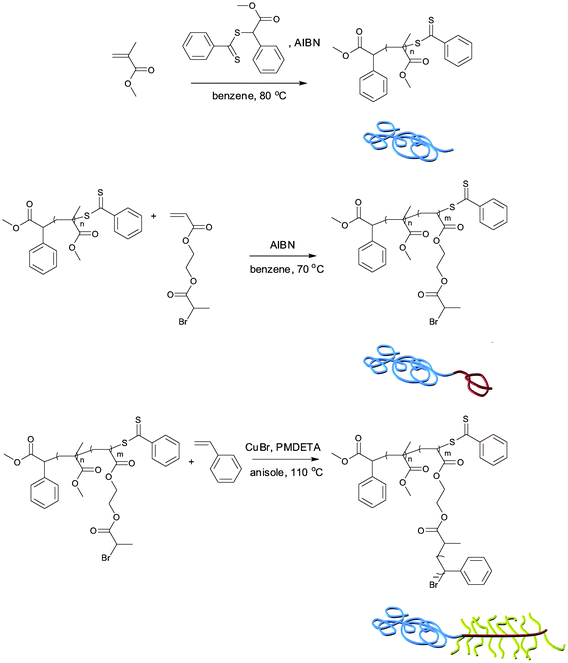 | ||
| Scheme 1 Synthetic route for PMMA-b-PBPEA-g-PS (blue: PMMA; red: PBPEA; yellow: PS). | ||
| Entrya | Polymerization time |
![[M with combining macron]](https://www.rsc.org/images/entities/i_char_004d_0304.gif) n
(×103)b
n
(×103)b |
![[M with combining macron]](https://www.rsc.org/images/entities/i_char_004d_0304.gif) w
(×103)b
w
(×103)b |
PDIb |
|---|---|---|---|---|
| a Degree of polymerization, shown in subscript, was calculated by conversion in the case of PMMA and by integration compared to PMMA in the cases of PBPEA and PS, based on 1H NMR spectra in CDCl3. b Determined by THF-GPC using a RI detector, based on polystyrene standards. | ||||
| PMMA480 | 22 hr | 45 | 59 | 1.28 |
| PMMA480-b-PBPEA100 | 13 hr | 53 | 75 | 1.43 |
| PMMA480-b-PBPEA100-g-PS2.4 | 10 min | 67 | 94 | 1.40 |
| PMMA480-b-PBPEA100-g-PS6.3 | 30 min | 77 | 106 | 1.37 |
| PMMA480-b-PBPEA100-g-PS8.4 | 50 min | 84 | 116 | 1.38 |
| PMMA480-b-PBPEA100-g-PS12.2 | 90 min | 97 | 131 | 1.36 |
| PMMA480-b-PBPEA100-g-PS17.7 | 130 min | 110 | 150 | 1.36 |
| PMMA480-b-PBPEA100-g-PS19.1 | 240 min | 125 | 189 | 1.51 |
The appropriate choice of the RAFT agent and the monomer bearing an initiating site for ATRP was crucial to achieve a controlled polymerization because the chain transfer of dithiocarbamates and halogen groups often compete in either ATRP or RAFT conditions.29 BPEA was employed in the RAFT process because free radical polymerization of BPEA has been reported to produce linear polymers without crosslinking.33 Indeed, the relatively small chain transfer constant of the secondary bromide moiety of BPEA enabled the growth of the PBPEA block up to 25 kDa without significant broadening of the PDI. In the ATRP process, the dithiocarbamate end group might participate in the polymerization process. However, the dithiocarbamate end group can be simply regarded as one more initiating site along the PBPEA block after all. The narrower PDI after ATRP of styrene supports the assumption that the resulting architecture and controllability were not affected by the dithiocarbamate end groups.
1H NMR spectra of the polymers taken after each step clearly show successful incorporation of each block, indicated by the appearance of methoxy protons corresponding to PMMA at 3.6 ppm, methine protons corresponding to PBPEA at 4.4 ppm, and aromatic protons corresponding to PS at 6.5–7.3 ppm, respectively (Fig. 1). Also, the GPC chromatograms of the polymers show that molecular weights of the polymers increased in a controlled manner reflected by the shift of unimodal chromatograms into the higher molecular weight region (Fig. 2). It should be noticed that the hydrodynamic volume of the branched polymers decreases and therefore branched polymers elute later during GPC analysis as compared to their linear analogues of similar molecular weight.23 However, it was found that an uncontrolled fraction of high-molecular-weight polymer appeared during ATRP of styrene when the polymerization time reached 240 minutes. It seems that coupling of growing PS chains, grafted on the PBPEA backbone, produced high-molecular-weight polymers. Therefore PMMA480-b-PBPEA100-g-PS19.1 was excluded for the further studies.
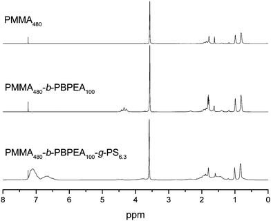 | ||
| Fig. 1 1H NMR spectra (400 MHz, CDCl3) of PMMA480 and PMMA480-b-PBPEA100 by the RAFT process, and PMMA480-b-PBPEA100-g-PS6.3 by ATRP. | ||
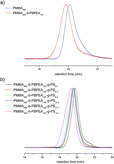 | ||
| Fig. 2 GPC chromatograms of the polymers measured by THF-GPC using a RI detector: (a) PMMA480 and PMMA480-b-PBPEA100 by the RAFT process, and (b) PMMA480-b-PBPEA100-g-PS2.4–19.1 by ATRP. | ||
Differential scanning calorimetry (DSC) thermograms of the polymers are shown in Fig. 3. PMMA-b-PBPEA shows two distinct glass transition temperatures (Tg) corresponding to the PMMA block (115 °C) and the PBPEA block (3 °C), suggesting that the two blocks are phase-separated. When a PS block was grafted on the PBPEA block, a large glass transition of the PS block appeared at 80 °C in addition to those of the PMMA block (124 °C) and the PBPEA block (−1 °C). These DSC results indicate that the incompatibility of the three different blocks was maintained in the CCBCP architecture. Even though the phase separation of grafted polymers is more difficult than that of linear analogues due to the lowered entropy,34 the DSC results suggest the possibility of formation of nanostructures by microphase separation.
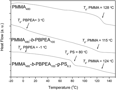 | ||
| Fig. 3 DSC thermograms of the polymers. All thermograms were recorded during the 2nd heating scan, at 10 °C/min under N2. | ||
Phase separation of CCBCPs
To investigate the microphase separation behavior of the polymers, films of PMMA-b-PBPEA-g-PS with a thickness of ∼43 nm were prepared by spin coating toluene solutions of PMMA-b-PBPEA-g-PS onto bare Si wafers, annealing at 200 °C under vacuum for a day, and then exposure to UV to crosslink PS and degrade PMMA. The morphologies of the resulting films were investigated with atomic force microscopy (AFM) and are shown in Fig. 4. PMMA480-b-PBPEA100-g-PS2.4, which contains the smallest volume fraction of PS (29%) employed in this study, does not show a phase-separated structure, presumably because the amount of PS in this copolymer is insufficient (Fig. 4b). The other polymers with higher DPs of PS develop vertical cylindrical PMMA morphologies on the bare Si wafers.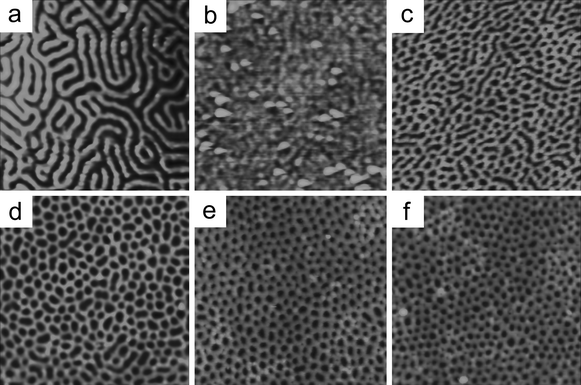 | ||
| Fig. 4 AFM images of PMMA-b-PBPEA-g-PS with different DPs of PS and the comparative linear PS-b-PMMA analogue with similar molecular weights (Polymer Source, Inc., 64 kDa–35 kDa) on a bare Si wafer. Scanned area was 1 µm × 1 µm for every sample. (a) Linear PS-b-PMMA, (b) PMMA480-b-PBPEA100-g-PS2.4, (c) PMMA480-b-PBPEA100-g-PS6.4, (d) PMMA480-b-PBPEA100-g-PS8.4, (e) PMMA480-b-PBPEA100-g-PS12.2, and (f) PMMA480-b-PBPEA100-g-PS17.7. | ||
In particular, PMMA480-b-PBPEA100-g-PS17.7 contains a large volume fraction of PS (75%) and develops a vertical cylindrical PMMA morphology without any parallel defects. Fig. 5a shows a representative AFM image of PMMA480-b-PBPEA100-g-PS17.7 on a bare Si wafer. It is clear that vertically oriented pores with a diameter of approx. 35 nm, which appear as black dots, are present over a large area. Considering the architecture and volume fraction of PMMA480-b-PBPEA100-g-PS17.7, the phase-separated structure should consist of PMMA cylinders surrounded by PBPEA chains and grafted PS chains filling the matrix, as shown in the inset in Fig. 5a. The cylinders were transformed into cylindrical pores by UV and O2 plasma treatments, after which a crosslinked PS matrix remains. The cross-sectional scanning electron microscopy (SEM) image of an identical sample confirms that the vertical cylinders extend from the film surface to the underlying substrate within the resolution limit of the microscope35 (Fig. 5b). Compared to the perfect perpendicular orientation, the lateral hexagonal ordering of the cylinders was not high probably because of the relatively broad molecular weight distribution of the polymer.
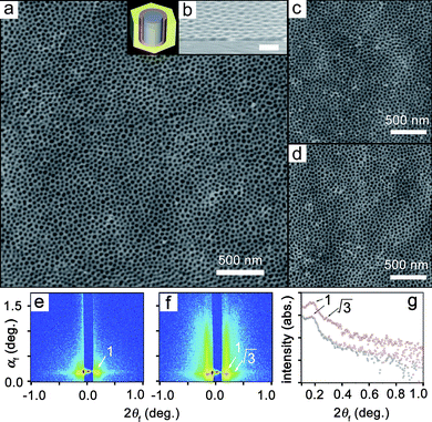 | ||
| Fig. 5 Cylindrical morphologies of PMMA480-b-PBPEA100-g-PS17.7 thin films oriented perpendicular to the film plane. The data scale of the AFM height images was set at 50 nm. (a) AFM height image of a polymer thin film on a bare Si wafer (inset: schematic diagram of the phase-separated structure: blue, PMMA; red, PBPEA; yellow, PS). (b) Cross-sectional SEM image of the sample (scale bar: 100 nm). (c) AFM image of a film on a HMDS-treated Si wafer. (d) AFM image of a film on a piranha-washed Si wafer. (e, f) 2D GIXS patterns measured at an incidence angle αi = 0.18° for films on bare Si wafers before (e) and after (f) etching with UV-exposure and O2 plasma treatment. (g) In-plane GIXS profiles extracted along the 2αf direction at αf = 0.20° from the GIXS patterns in e (black circles) and f (red circles). | ||
It is striking that the perpendicular orientation to the substrate was achieved without any additional treatments compared to the perfect parallel orientation of the linear analogue (Fig. 4a). More interestingly, PMMA480-b-PBPEA100-g-PS17.7 produces identical images with cylinders oriented perpendicular to the substrates on a piranha-washed Si wafer (Fig. 5c) and on a hexamethyldisilazane (HMDS)-treated Si wafer (Fig. 5d). It is surprising to find that the cylinders maintain their vertical orientation on substrates with different surface energies (the water contact angles are approx. 55° for bare Si, <10° for piranha-washed Si, and approx. 90° for HMDS-treated Si36). The above phase-separation results suggest that the PMMA cylinders and PS matrix always co-adsorb regardless of the substrate.
The PMMA480-b-PBPEA100-g-PS17.7 films on bare Si wafers before and after etching with UV-exposure and O2 plasma treatment were further investigated by using synchrotron grazing incidence X-ray scattering (GIXS) analysis (Fig. 5e–g).4,37,38 Strip-shaped patterns showing typical scattering characteristics for a hexagonally packed structure of vertically oriented cylinders were obtained.4,38 These results indicate that the nanopores generated in the film by the selective etching process are cylindrical and well oriented perpendicular to the film plane. The average separation between the cylinders was determined to be 43.9 nm from the scattering strips, which is in good agreement with the AFM results. Moreover, the average separation value was found to be the same as that determined for a structure of phase-separated PMMA blocks from the GIXS pattern of the unetched film, confirming that the vertically oriented nanopores originate from the PMMA domain.
We propose that the formation of the perpendicularly oriented cylindrical morphology is thermodynamically driven by two factors, i.e., segregation of the blocks and stretching of the grafted chains, regardless of the interaction with the surface (Fig. 6). The additional interaction of the densely grafted C blocks is attributed to overcoming the effect of surface energy of the substrate. According to the spreading argument for densely grafted polymers,39 the PS chains spread across the surface to minimize steric repulsion between the chains and to increase the contact with the substrate. Whereas homo-grafted polymers exhibit an even distribution of grafted chains, a linear PMMA chain attached to a PBPEA backbone induces phase separation from the PS chains and confines the spreading direction away from PMMA. In the given arrangement, an intrinsic positive curvature with respect to PMMA arises due to the stretching of the PS chains, which results in the formation of a cylindrical morphology consisting of PMMA cylinders, the PS matrix, and the PBPEA interface. Dissipative particle dynamics simulations for A-b-B-g-C type block copolymers suggested a similar morphology, the large-length scale ordered structure with most of the B segregated along the interfaces between the A-rich and C-rich domains if the interaction parameter between A and B blocks is smaller than that of A and C blocks.40
 | ||
| Fig. 6 Microphase separation of PMMA-b-PBPEA-g-PS on a surface. (a) Comb-coil type architecture of the polymer. (b) Phase separation between the three blocks and the spreading of PS chains grafted onto a PBPEA block over the surface induces an intrinsic curvature. (c) Vertically oriented cylinders are thus always developed that (d) can be readily transformed into a nanoporous structure. | ||
Even if the surface exhibits a higher affinity toward a specific block, the phase separation between PMMA and PS and the steric repulsion between the grafted PS chains always induce co-adsorption of the three blocks on the substrate, resulting in the growth of vertical cylinders. The DP of the grafted PS chains plays a crucial role in this system because it determines the incompatibility between the blocks (according to χN) as well as the steric repulsion between the PS chains.
The ability of PMMA-b-PBPEA-g-PS to form vertically oriented cylindrical morphologies on substrates with very different surface energies opens up a wide range of applications. The perpendicular orientation with respect to the film plane was demonstrated on a variety of substrates including metals (Au and Cu) and a polymer (crosslinked SU-8 resin). The AFM images of films of PMMA480-b-PBPEA100-g-PS17.7 on these substrates in Fig. 7 clearly show that the comb-coil block copolymer exhibits a vertically oriented cylindrical morphology on every substrate tested, and support the surface-independence of the phase-separated structure. Interestingly, even in the AFM image for the rough Cu foil shown in Fig. 7e, it is clear that vertically oriented cylinders form that follow the roughness of the substrate.
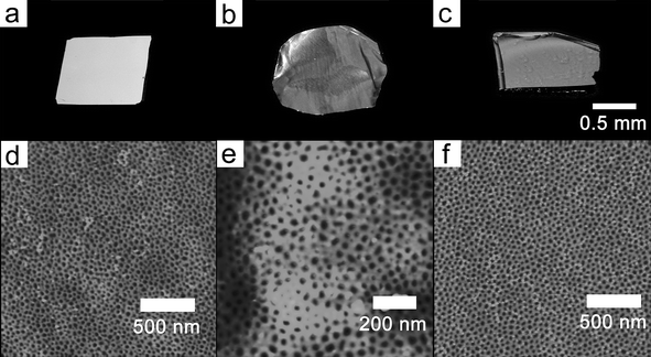 | ||
| Fig. 7 Photoimages of various substrates (a–c) treated with PMMA480-b-PBPEA100-g-PS17.7 and corresponding AFM height images (d–f). (a, d) Au substrate. (b, e) Cu substrate. (c, f) crosslinked SU-8 resin. The data scale of the images was set at 40 nm. | ||
Inspired by the above results, we investigated the phase-separation behavior of PMMA480-b-PBPEA100-g-PS17.7 on a patterned surface prepared with a photolithographic technique, in order to explore the possibility of microphase separation on a chemically and topologically heterogeneous surface. Line-patterned SU-8 resins (∼50 nm thick) with various line spacings were fabricated by using UV lithography on a Si wafer, and a film of PMMA480-b-PBPEA100-g-PS17.7 was prepared on this substrate by spin-coating and subjected to UV and O2 plasma treatments. This process is illustrated in Fig. 8a–d.
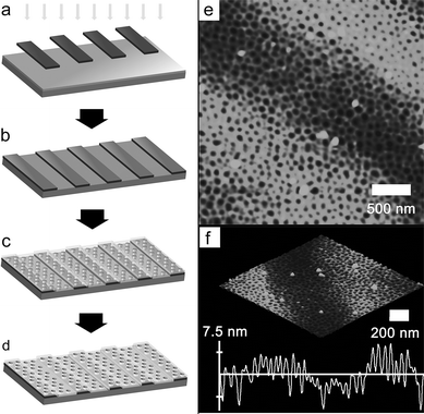 | ||
| Fig. 8 Fabrication of a vertically oriented porous film on a line-patterned surface. (a) Selective irradiation with UV by using a line-patterned photomask on a Si wafer coated with the SU-8 precursor solution. (b) Patterned SU-8 resin on a Si wafer. (c) Phase separation of PMMA480-b-PBPEA100-g-PS17.7 on the substrate. (d) Vertically oriented porous film formed after UV and O2 plasma treatments. (e) AFM height image of the porous film on a line-patterned SU-8 resin. (f) Height information for the region depicted in (e). | ||
Because the thicknesses of the SU-8 resin and the PMMA480-b-PBPEA100-g-PS17.7 film are comparable, a film with a groove that depends on the underlying pattern is expected to form. As expected, the AFM images in Fig. 8e and f show that vertically oriented cylinders are present on the SU-8 surfaces as well as on the Si surfaces regardless of the line spacing, with variations in height according to the topology of the surface. The cylindrical morphology is even maintained near the edges. These results demonstrate the surface-independence of the coil-comb architecture on a heterogeneous surface.
Conclusion
We have developed a novel strategy for generating block copolymer films consisting of cylindrical microdomains oriented perpendicular to the film plane; this orientation is independent of the substrate. By combining the RAFT and ATRP techniques, PMMA-b-PBPEA-g-PS with a comb-coil architecture was readily synthesized. The polymer exhibits vertically oriented cylindrical morphologies on various substrates that are driven by this architecture, which overcomes the interactions between the substrates and the polymer chains. The formation of vertically oriented cylindrical pores on patterned surfaces was also demonstrated. This type of block copolymer may find applications where the underlying substrate is important for reactions such as Au surface for binding of thiols41 or electrochemical growth of conducting polymer nanotubes.42Acknowledgements
We thank Prof. P. A. Pincus at the University of California, Santa Barbara for valuable discussion. This work was supported by KOSEF through the ERC (R11-2007-050-04001-0) and NRL (R0A-2008-000-20121-0) programs. M. Ree appreciates the financial support of KOSEF (NRL Program and Center for Electro-Photo Behaviors in Advanced Molecular Systems) and Korean Ministry of Education, Science & Technology (MEST) (BK21 Program and World Class University Program). The synchrotron X-ray scattering measurements were supported by MEST, POSCO and POSTECH Foundation.Notes and references
- H.-C. Kim and W. D. Hinsberg, J. Vac. Sci. Technol., 2008, A26, 1369–1382 Search PubMed; D. A. Olson, L. Chen and M. A. Hillmyer, Chem. Mater., 2008, 20, 869–890 CrossRef CAS.
- (a) M. Park, P. M. Chaikin, R. A. Register and D. H. Adamson, Appl. Phys. Lett., 2001, 79, 257–259 CrossRef CAS; (b) J. Y. Cheng, C. A. Ross, V. Z.-H. Chan, E. L. Thomas, R. G. H. Lammertink and G. J. Vancso, Adv. Mater., 2001, 13, 1174–1178 CrossRef CAS.
- C. T. Black, K. W. Guarini, K. R. Milkove, S. M. Baker, T. P. Russell and M. T. Tuominen, Appl. Phys. Lett., 2001, 79, 409–411 CrossRef CAS.
- (a) J. Yoon, S. Y. Yang, B. Lee, W. Joo, K. Heo, J. K. Kim and M. Ree, J. Appl. Crystallogr., 2007, 40, 305–312 CrossRef CAS; (b) S. Y. Yang, J. Park, J. Yoon, M. Ree, S. K. Jang and J. K. Kim, Adv. Funct. Mater., 2008, 18, 1371–1377 CrossRef CAS.
- (a) K. Shin, K. A. Leach, J. T. Goldbach, D. H. Kim, J. Y. Jho, M. Tuominen, C. J. Hawker and T. P. Russell, Nano Lett., 2002, 2, 933–936 CrossRef CAS; (b) K. Aissou, T. Baron, M. Kogelschatz, M. Den Hertog, J. L. Rouvière, J.-M. Hartmann and B. Pélissier, Chem. Mater., 2008, 20, 6183–6188 CrossRef CAS.
- T. Thurn-Albrecht, J. Schotter, G. A. Kästle, N. Emley, T. Shibauchi, L. Krusin-Elbaum, K. Guarini, C. T. Black, M. T. Tuominen and T. P. Russell, Science, 2000, 290, 2126–2129 CrossRef CAS.
- (a) Y.-T. Tseng, W.-H. Tseng, C.-H. Lin and R.-M. Ho, Adv. Mater., 2007, 19, 3584–3588 CrossRef CAS; (b) O. Seifarth, R. Krenek, I. Tokarev, Y. Burkov, A. Sidorenko, S. Minko, M. Stamm and D. Schmeißer, Thin Solid Films, 2007, 515, 6552–6556 CrossRef CAS; (c) E. J. W. Crossland, S. Ludwigs, M. A. Hillmyer and U. Steiner, Soft Matter, 2007, 3, 94–98 RSC.
- (a) K.-H. Lo, W.-H. Tseng and R.-M. Ho, Macromolecules, 2007, 40, 2621–2624 CrossRef CAS; (b) S. Park, B. Kim, J.-Y. Wang and T. P. Russell, Adv. Mater., 2008, 20, 681–685 CrossRef CAS.
- (a) D. J. Milliron, M. A. Caldwell and H.-S. P. Wong, Nano Lett., 2007, 7, 3504–3507 CrossRef CAS; (b) D. J. Milliron, S. Raoux, R. M. Shelby and J. Jordan-Sweet, Nat. Mater., 2007, 6, 352–356 CrossRef CAS.
- (a) T. Thurn-Albrecht, R. Steiner, J. DeRouchey, C. M. Stafford, E. Huang, M. Bal, M. Tuominen, C. J. Hawker and T. P. Russell, Adv. Mater., 2000, 12, 787–791 CrossRef CAS; (b) K. W. Guarini, C. T. Black and S. H. Yeung, Adv. Mater., 2002, 14, 1290–1294 CrossRef CAS.
- (a) S. O. Kim, H. H. Solak, M. P. Stoykovich, N. J. Ferrier, J. J. de Pablo and P. F. Nealey, Nature, 2003, 424, 411–414 CrossRef CAS; (b) M. P. Stoykovich, M. Müller, S. O. Kim, H. H. Solak, E. W. Edwards, J. J. de Pablo and P. F. Nealey, Science, 2005, 308, 1442–1446 CrossRef CAS; (c) R. Ruiz, H. Kang, F. A. Detcheverry, E. Dobisz, D. S. Kercher, T. R. Albrecht, J. J. de Pablo and P. F. Nealey, Science, 2008, 321, 936–939 CrossRef CAS.
- (a) R. A. Segalman, H. Yokoyama and E. J. Kramer, Adv. Mater., 2001, 13, 1152–1155 CrossRef CAS; (b) J. Y. Cheng, A. M. Mayes and C. A. Ross, Nat. Mater., 2004, 3, 823–828 CrossRef CAS; (c) I. Bita, J. K. W. Yang, Y. S. Jung, C. A. Ross, E. L. Thomas and K. K. Berggren, Science, 2008, 321, 939–943 CrossRef CAS.
- S. Sakurai, Polymer, 2008, 49, 2781–2796 CrossRef CAS.
- (a) S. H. Kim, M. J. Misner, T. Xu, M. Kimura and T. P. Russell, Adv. Mater., 2004, 16, 226–231 CrossRef CAS; (b) J. Bang, S. H. Kim, E. Drockenmuller, M. J. Misner, T. P. Russell and C. J. Hawker, J. Am. Chem. Soc., 2006, 128, 7622–7629 CrossRef CAS; (c) C. Tang, E. M. Lennon, G. H. Fredrickson, E. J. Kramer and C. J. Hawker, Science, 2008, 322, 429–432 CrossRef CAS.
- (a) P. Mansky, Y. Liu, E. Huang, T. P. Russell and C. J. Hawker, Science, 1997, 275, 1458–1460 CrossRef CAS; (b) I. In, Y.-H. La, S.-M. Park, P. F. Nealey and P. Gopalan, Langmuir, 2006, 22, 7855–7860 CrossRef CAS; (c) E. Han, K. O. Stuen, Y.-H. La, P. F. Nealey and P. Gopalan, Macromolecules, 2008, 41, 9090–9097 CrossRef CAS.
- S. Ham, C. Shin, E. Kim, D. Y. Ryu, U. Jeong, T. P. Russell and C. J. Hawker, Macromolecules, 2008, 41, 6431–6437 CrossRef CAS.
- D. Y. Ryu, K. Shin, E. Drockenmuller, C. J. Hawker and T. P. Russell, Science, 2005, 308, 236–239 CrossRef CAS.
- S.-J. Jeong, G. Xia, B. H. Kim, D. O. Shin, S.-H. Kwon, S.-W. Kang and S. O. Kim, Adv. Mater., 2008, 20, 1898–1904 CrossRef CAS.
- C. Tsitsilianis, in Macromolecular Engineering, eds. K. Matyjaszewski, Y. Gnanou and L. Leibler, WILEY-VCH, Weinheim, 2006, vol. 2, pp. 860–870 Search PubMed.
- (a) J. Ruokolainen, R. Mäkinen, M. Torkkeli, T. Mäkelä, R. Serimaa, G. ten Brinke and O. Ikkala, Science, 1998, 280, 557–560 CrossRef CAS; (b) J. Ruokolainen, M. Saariaho, O. Ikkala, G. ten Brinke, E. L. Thomas, M. Torkkeli and R. Serimaa, Macromolecules, 1999, 32, 1152–1158 CrossRef CAS; (c) E. Polushkin, G. O. R. A. van Ekenstein, M. Knaapila, J. Ruokolainen, M. Torkkeli, R. Serimaa, W. Bras, I. Dolbnya, O. Ikkala and G. ten Brinke, Macromolecules, 2001, 34, 4917–4922 CrossRef CAS; (d) R. Mäki-Ontto, K. de Moel, W. de Odorico, J. Ruokolainen, M. Stamm, G. ten Brinke and O. Ikkala, Adv. Mater., 2001, 13, 117–121 CrossRef CAS; (e) S. Valkama, T. Ruotsalainen, A. Nykänen, A. Laiho, H. Kosonen, G. ten Brinke, O. Ikkala and J. Ruokolainen, Macromolecules, 2006, 39, 9327–9336 CrossRef CAS.
- (a) B. Nandan, C.-H. Lee, H.-L. Chen and W.-C. Chen, Macromolecules, 2005, 38, 10117–10126 CrossRef CAS; (b) B. Nandan, C.-H. Lee, H.-L. Chen and W.-C. Chen, Macromolecules, 2006, 39, 4460–4468 CrossRef CAS; (c) H.-L. Chen, J.-S. Lu, C.-H. Yu, C.-L. Yeh, U.-S. Jeng and W.-C. Chen, Macromolecules, 2007, 40, 3271–3276 CrossRef CAS; (d) W.-S. Chiang, C.-H. Lin, B. Nandan, C.-L. Yeh, M. H. Rahman, W.-C. Chen and H.-L. Chen, Macromolecules, 2008, 41, 8138–8147 CrossRef CAS.
- (a) P. Moschogianni, S. Pispas and N. Hadjichristidis, J. Polym. Sci., Part A: Polym. Chem., 2001, 39, 650–655 CrossRef CAS; (b) G. D. Fu, S. J. Phua, E. T. Kang and K. G. Neoh, Macromolecules, 2005, 38, 2612–2619 CrossRef CAS; (c) Z. Cheng, X. Zhu, G. D. Fu, E. T. Kang and K. G. Neoh, Macromolecules, 2005, 38, 7187–7192 CrossRef CAS; (d) C. Li, Y. Shi and Z. Fu, Polym. Int., 2006, 55, 25–30 CrossRef CAS; (e) Z. Fu, W. Tao and Y. Shi, J. Polym. Sci., Part A: Polym. Chem., 2008, 46, 362–372 CrossRef CAS.
- R. Venkatesh, L. Yajjou, C. E. Koning and B. Klumperman, Macromol. Chem. Phys., 2004, 205, 2161–2168 CrossRef CAS.
- (a) F. Xu, T. Li, J. Xia, F. Qiu and Y. Yang, Polymer, 2007, 48, 1428–1434 CrossRef CAS; M. B. Runge and N. B. Bowden, J. Am. Chem. Soc., 2007, 129, 10551–10560 CrossRef CAS; (b) M. B. Runge, C. E. Lipscomb, L. R. Ditzler, M. K. Mahanthappa, A. V. Tivanski and N. B. Bowden, Macromolecules, 2008, 41, 7687–7694 CrossRef CAS.
- G. Moad, E. Rizzardo and S. H. Thang, Acc. Chem. Res., 2008, 41, 1133–1142 CrossRef CAS.
- K. Matyjaszewski and J. Xia, Chem. Rev., 2001, 101, 2921–2990 CrossRef CAS.
- (a) C. M. Wager, D. M. Haddleton and S. A. F. Bon, Eur. Polym. J., 2004, 40, 641–645 CrossRef CAS; (b) C. D. Petruczok, R. F. Barlow and D. A. Shipp, J. Polym. Sci., Part A: Polym. Chem., 2008, 46, 7200–7206 CrossRef CAS; (c) M. D. Rowe, B. A. G. Hammer and S. G. Boyes, Macromolecules, 2008, 41, 4147–4157 CrossRef CAS.
- (a) Y.-Y. Tong, Y.-Q. Dong, F.-S. Du and Z.-C. Li, Macromolecules, 2008, 41, 7339–7346 CrossRef CAS; C. Liu, Y. Zhang and J. Huang, Macromolecules, 2008, 41, 325–331 CrossRef CAS; (b) K. Ranganathan, R. Deng, R. K. Kainthan, C. Wu, D. E. Brooks and J. N. Kizhakkedathu, Macromolecules, 2008, 41, 4226–4234 CrossRef CAS.
- (a) K. Matyjaszewski and K. R. Poil, Macromolecules, 2005, 38, 8093–8100 CrossRef CAS; R. Nicolaÿ, Y. Kwak and K. Matyjaszewski, Macromolecules, 2008, 38, 4585–4596; (b) Y. Kwak, R. Nicolaÿ and K. Matyjaszewski, Macromolecules, 2008, 41, 6602–6604 CrossRef CAS; (c) W.-M. Wan and C.-Y. Pan, Macromolecules, 2008, 41, 5085–5088 CrossRef CAS; (d) Z. Zhang, W. Zhang, X. Zhu, Z. Cheng and J. Zhu, J. Polym. Sci., Part A: Polym. Chem., 2007, 45, 5722–5730 CrossRef CAS; (e) X. Xue, W. Zhang, Z. Cheng, J. Zhu and X. Zhu, J. Polym. Sci., Part A: Polym. Chem., 2008, 46, 5626–5637 CrossRef CAS.
- K. L. Beers, S. G. Gaynor and K. Matyjaszewski, Macromolecules, 1998, 31, 9413–9415 CrossRef CAS.
- S. Perrier, P. Takolpuckdee, J. Westwood and D. M. Lewis, Macromolecules, 2004, 37, 2709–2717 CrossRef CAS.
- J. Yoon, K.-W. Kim, J. Kim, K. Heo, K. S. Jin, S. Jin, T. J. Shin, B. Lee, Y. Rho, B. Ahn and M. Ree, Macromol. Res., 2008, 16, 575–585 Search PubMed.
- M. C. Rusu, M. Rusu, M. Popa, C. Delaite and G. Riess, Polym. Bull., 2007, 59, 25–30 CrossRef CAS.
- N. Hadjichristidis, S. Pispas and G. Floudas, Block Copolymers: Synthetic Strategies, Physical Properties, and Applications, Wiley, Hoboken, NJ, 2003, p. 271 Search PubMed.
- K. Fukunaga, A. E. Ribbe and T. Hashimoto, Macromolecules, 2006, 39, 6171–6179 CrossRef CAS.
- M. Wolff, B. Akgun, M. Walz, A. Magerl and H. Zabel, Europhys. Lett., 2008, 82, 36001 CrossRef.
- (a) B. Lee, Y.-H. Park, Y.-T. Hwang, W. Oh, J. Yoon and M. Ree, Nat. Mater., 2005, 4, 147–150 CrossRef CAS; (b) B. Lee, W. Oh, Y. Hwang, Y.-H. Park, J. Yoon, K. S. Jin, K. Heo, J. Kim, K.-W. Kim and M. Ree, Adv. Mater., 2005, 17, 696–701 CrossRef CAS; (c) B. Lee, I. Park, J. Yoon, S. Park, J. Kim, K.-W. Kim, T. Chang and M. Ree, Macromolecules, 2005, 38, 4311–4323 CrossRef CAS; (d) S. Jin, J. Yoon, K. Heo, H.-W. Park, J. Kim, K.-W. Kim, T. J. Shin, T. Chang and M. Ree, J. Appl. Crystallogr., 2007, 40, 950–958 CrossRef CAS; (e) J. Yoon, S. Jin, B. Ahn, Y. Rho, T. Hirai, R. Maeda, T. Hayakawa, J. Kim, K.-W. Kim and M. Ree, Macromolecules, 2008, 41, 8778–8784 CrossRef CAS; (f) J. Yoon, S. Y. Jung, B. Ahn, K. Heo, S. Jin, T. Iyoda, H. Yoshida and M. Ree, J. Phys. Chem. B, 2008, 112, 8486–8495 CrossRef CAS.
- K. Heo, J. Yoon, S. Jin, J. Kim, K.-W. Kim, T. J. Shin, B. Chung, T. Chang and M. Ree, J. Appl. Crystallogr., 2008, 41, 281–291 CrossRef CAS.
- S. S. Sheiko, F. C. Sun, A. Randall, D. Shirvanyants, M. Rubinstein, H. Lee and K. Matyjaszewski, Nature, 2006, 440, 191–194 CrossRef CAS.
- C.-I. Huang and Y.-C. Lin, Macromol. Rapid Commun., 2007, 28, 1634–1639 CrossRef CAS.
- J. M. Jung, K. Y. Kwon, T.-H. Ha, B. H. Chung and H. T. Jung, Small, 2006, 2, 1010–1015 CrossRef CAS.
- J. I. Lee, S. H. Cho, S.-M. Park, J. K. Kim, J. K. Kim, J.-W. Yu, Y. C. Kim and T. P. Russell, Nano Lett., 2008, 8, 2315–2320 CrossRef CAS.
| This journal is © The Royal Society of Chemistry 2010 |
