Advanced materials and processes for polymer solar cell devices
Martin
Helgesen
,
Roar
Søndergaard
and
Frederik C.
Krebs
*
Risø National Laboratory for Sustainable Energy, Technical University of Denmark, Frederiksborgvej 399, DK-4000 Roskilde, Denmark. E-mail: frkr@risoe.dtu.dk
First published on 14th October 2009
Abstract
The rapidly expanding field of polymer and organic solar cells is reviewed in the context of materials, processes and devices that significantly deviate from the standard approach which involves rigid glass substrates, indium-tin-oxide electrodes, spincoated layers of conjugated polymer/fullerene mixtures and evaporated metal electrodes in a flat multilayer geometry. It is likely that significant advances can be found by pursuing many of these novel ideas further and the purpose of this review is to highlight these reports and hopefully spark new interest in materials and methods that may be performing less than the current state-of-the-art in their present form but that may have the potential to outperform these pending a larger investment in effort.
 Martin Helgesen | Martin Helgesen received his Master of Science in Chemistry from The University of Copenhagen in 2006. The same year he began his PhD under the mentorship of Frederik Christian Krebs at Risø National Laboratory for Sustainable Energy, Technical University of Denmark. His research interests are in developing thermocleavable low band gap polymers and their thin films for organic photovoltaics. |
 Roar Søndergaard | Roar Søndergaard received his M.Sc. in 2005 from the Department of Chemistry at the University of Copenhagen. After working as a research assistant first at The University of Copenhagen and later at Risø DTU National Laboratory for Sustainable Energy he is currently pursuing his PhD at Risø DTU. His research interests include synthesis of conjugated polymers and synthesis of polymers that allow for different processing methods when preparing organic photovoltaics. |
 Frederik C. Krebs | Frederik Christian Krebs received his PhD from the Technical University of Denmark in year 2000 and has since then worked in the field of polymer solar cells at Risø National Laboratory for Sustainable Energy. The areas of research include new materials with low band gap and novel processing capability, large area processing and manufacture of polymer solar cells, stability and lifetime testing, degradation mechanism studies, outside testing and demonstration. |
Introduction
Encouraging progress has been made over the last few years in the field of photovoltaics using organic materials. Conventional solar cells are built from inorganic materials such as silicon. While the efficiency of such conventional solar cells is high, very expensive materials and energy consuming processing techniques are required. The main reason for the extensive interest in organic semiconducting materials is their potential for the realization of a low cost, easily processed and flexible renewable energy source. Conjugated polymers are an especially attractive alternative to the traditional silicon photovoltaics because they are strong absorbers of visible light and can be deposited onto flexible substrates over large areas using wet-processing techniques such as roll-to-roll coating or printing. Many reviews,1–26 special issues,27–33 and books34–38 on the topic of polymer solar cells have been published during the past 5 years and the definitions are quite broad spanning all polymer solar cells, polymer–fullerene solar cells, small molecule and hybrid solar cells. Polymer–fullerene solar cells based on composites of an electron-donating conjugated polymer and an electron-accepting fullerene has proven to be the most successful of them so far and is advancing rapidly towards commercial viability. Although the performance of polymer solar cells has increased steadily with power conversion efficiencies (PCEs) exceeding 6%, further improvements in efficiency are required for large scale commercialization. Aside from the power conversion efficiency, processing and stability are two other important aspects that have to be addressed with equal intensity for the success of polymer and organic solar cells. To combine all three parameters into a useful technology further research in device science and new materials is needed.Aim of this review
We seek to identify novel ideas in the form of materials, methods and device concepts that can potentially house the possibility to go beyond the current state-of-the-art. Armed with the identity of the potential candidates we further suggest how research might be directed towards real progress in terms of better performance, higher operational stability, facile processing and easier, faster and lower cost production.Materials
State-of-the-art
Since the first report of photoinduced charge transfer from a conjugated polymer to a buckminsterfullerene (C60) in 1992 by Sariciftci et al.,39 the field of polymer–fullerene solar cells has been through a dynamic development. In 1995 Yu et al. demonstrated a successful method to dissociate excitons and produce free charge carriers in organic semiconductors.40 For the photoactive layer the authors used a blend of 2-methoxy-5-(2-ethylhexyloxy)-polyphenylenevinylene (MEH-PPV) as the electron donor and the soluble fullerene derivative [6,6]-phenyl C61 butyric acid methyl ester (PCBM) as the electron acceptor (Fig. 1).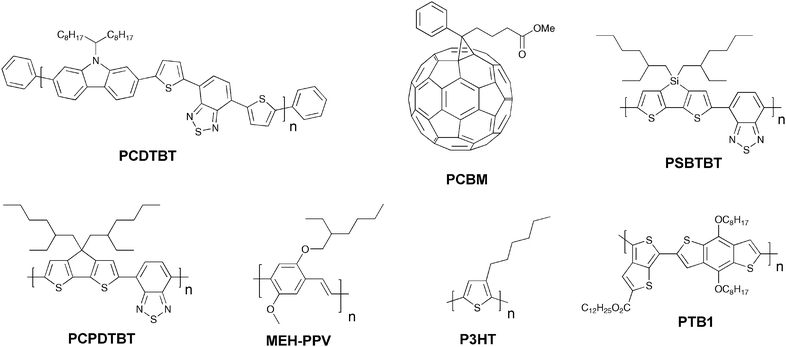
The solar cell based on a MEH-PPV:PCBM composite or a so called bulk heterojunction (BHJ) showed an estimated efficiency of nearly l% which was a major breakthrough for organic photovoltaics. When organic semiconductors absorb sunlight they mainly create excitons (electron–hole pairs) that are bound at room temperature. The exciton has to reach the donor–acceptor interface within its lifetime to transfer a free electron to the acceptor material and create a photovoltaic effect. Since the exciton diffusion range is limited, typically ∼3–10 nm in most organic semiconductors,41–43 which is much smaller than the necessary film thickness for effective optical absorption (50–250 nm), the key to an efficient solar cell requires that the excitons are generated in a nanoscale interpenetrating bicontinous network of donor and acceptor materials within the entire photoactive layer. A schematic illustration of a bulk heterojunction is shown in Fig. 2.
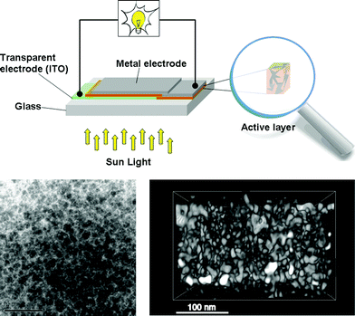 | ||
| Fig. 2 A schematic illustration of a bulk heterojunction device showing electrical contacts (top) and a TEM image of a phase separated blend (bottom left. Reprinted with permission from ref. 44. © 2007 John Wiley & Sons, Ltd.) and a reconstructed tomographic 3D-image (bottom right. Reprinted with permission from ref. 45. © 2009 American Chemical Society). | ||
From a materials point of view the state-of-the-art in the field of organic photovoltaics is currently represented by bulk heterojunction solar cells based on poly(3-hexylthiophene) (P3HT) and the fullerenes [60]PCBM (Fig. 1) and [70]PCBM where efficiencies in the 4–5% range have been reported.46–50 It should be noted that the reproducibility and average efficiencies are significantly lower than these “hero” devices which is caused by the sensitivity to the fabrication process. In addition the field has seen some inconsistent reports of unrealistically high efficiencies51–54 and this has led to the introduction of editorial procedures to avoid and/or eliminate fraud reports.54 To improve efficiencies further towards 10% new materials are needed because the P3HT:PCBM system is approaching optimal device performance. The main disadvantage of P3HT is the poor matching of its absorption spectrum with the solar emission spectrum. The band gap of P3HT is around 1.9 eV, limiting the absorbance to wavelengths below 650 nm. Since the photon flux reaching the surface of the earth from the sun has a maximum of approximately 1.8 eV (700 nm) P3HT is only able to harvest up to 22.4% of the available solar photons.6,20,54 Therefore, by decreasing the band gap of the active material it is possible to harvest a larger amount of the solar photons and thereby increase the power conversion efficiency. One of the most common techniques used to synthesise low band gap polymers is the donor–acceptor approach where alternating electron-rich and electron-poor units are incorporated in the polymer backbone. This causes a partial charge separation along the polymer backbone which generally gives the polymer a lower band gap.55 New low band gap polymer:PCBM composites have already shown device efficiencies close to and even exceeding that of P3HT:PCBM with plenty of room for improvement.56–58 One of the most efficient low band gap polymers to date is poly[2,6-(4,4-bis-(2-ethylhexyl)-4H-cyclopenta[2,1-b;3,4-b′]-dithiophene)-alt-4,7-(2,1,3-benzothiadiazole)] (PCPDTBT) (Fig. 1) which is based on a benzothiadiazole unit (acceptor) and a 4,4-bis(2-ethylhexyl)-4H-cyclopenta[2,1-b;3,4-b′]dithiophene unit (donor) that gives it an optical band gap around 1.46 eV. Zhu et al. have reported power conversion efficiencies up to 3.5% for bulk heterojunction solar cells based on PCPDTBT and [70]PCBM with a maximum EQE of 38% around 700 nm and over 25% in the wavelength range between 400 and 800 nm.59 Moreover it was demonstrated that by incorporating a few volume per cent of alkanedithiols in the solution used to process the films of PCPDTBT and [70]PCBM, the power-conversion efficiency could be increased to 5.5% through altering the bulk heterojunction morphology.58 This is one of the highest reported efficiencies for a low band gap polymer to date and there is still room for improvement according to the electrooptical properties of the polymer.60–62 Recently a power conversion efficiency of 6.1% was reported for a bulk heterojunction solar cell based on a blend of the polymer poly[N-9″-hepta-decanyl-2,7-carbazole-alt-5,5-(4′,7′-di-2-thienyl-2′,1′,3′-benzothiadiazole)] (PCDTBT) and [70]PCBM.63 The PCDTBT:[70]PCBM solar cells demonstrate the best performance of any single junction polymer solar cell studied to date. PCDTBT (Fig. 1) is based on a 4,7-dithienylbenzothiadiazole unit and a soluble carbazole unit that gives it an optical band gap around 1.88 eV.
Polymer–polymer solar cells for potentially higher performance
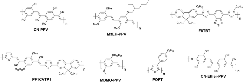
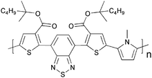
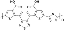
It is remarkable how little effort that has been put into making novel materials that deliberately solves the problems that limit the performance, stability and processing of the existing materials into devices. From this point of view the field has been highly successful and have managed to optimize the few known materials to their best level of performance by investing most of the effort into device optimisation using mainly physical techniques. It is noteworthy that the state-of-the-art solar cell has not evolved much since 1995 from a materials point of view and still comprise a polymer such as P3HT and a fullerene such as PCBM. However, it should be mentioned that significant progress has been made in developing novel materials, of both donor and fullerene acceptors, with optimal energy levels to improve the PCE.57,64–66Photovoltaic devices based on a blend of two conjugated polymers as the photoactive layer was first reported back in the 1990s,67,68 and as with polymer–fullerene solar cells, polymer–polymer solar cells are also based on a donor–acceptor pair. The first realizations of polymer–polymer solar cells were prepared from blends of MEH-PPV and poly(2,5,2′,5′-tetrahexyloxy-7,8′-dicyano-di-p-phenylenevinylene) (CN-PPV) (Fig. 3). MEH-PPV was acting as the donor and CN-PPV as the acceptor polymer. Since this initial report of polymer–polymer solar cells, they have not attracted as much attention as the polymer–fullerene solar cells. Despite their moderate performance (up to ∼1.8% PCE)69 photovoltaic devices based on polymer–polymer composites should potentially have several advantages to offer. While polymer:PCBM devices have shown efficiencies exceeding 6% it is predominantly the polymer that absorbs light since PCBM has a very weak overlap with the solar emission spectrum. Although [70]PCBM absorb more light and thus solves this problem to a limited degree, from a scientific point of view,70 a blend of two conjugated polymers could exhibit a high optical absorption coefficient and enable absorption of solar light over a wider spectral range. Furthermore, it is relatively uncomplicated to tune the donor–acceptor energy levels when using polymers as electron acceptors because of greater flexibility in the design of the materials. Polymer–polymer solar cells have a high potential but there is a big challenge in designing conducting n-type polymers with acceptor properties up to a level that can compete with fullerenes. A problem is that polymer blends have a tendency to phase separate into domains with dimensions of several micrometres and thus is not within the exciton diffusion range. Therefore the challenge for these systems is to find a combination where the two polymers have the right morphology for efficient phase separation into an interpenetrating network that allows for efficient charge carrier generation and transport. McNeill et al. have reported one of the best performing polymer–polymer solar cells to date with a PCE of 1.8%.69 The authors used a blend of P3HT as the donor component and poly[(9,9-dioctylfluorene)-2,7-diyl-alt-[4,7-bis(3-hexylthien-5-yl)-2,1,3-benzothiadiazole]-2,2-diyl] (F8TBT) as the n-type polymer (Fig. 3). The efficiency is somewhat lower than the state-of-the-art polymer–fullerene solar cell by a factor of 3–4 but higher efficiencies should be reachable if spectral overlap of the two polymers could be reduced, resulting in a wider spectral coverage. High efficiencies have also been reported for the polymer–polymer composites based on POPT:CN-PPV, MDMO-PPV:PF1CVTP1 and M3EH-PPV:CN-Ether-PPV (Fig. 3).71–73
Thermocleavable materials for higher level processing and stability
Historically conjugated polymer materials were prepared via a precursor route whereby a thermal treatment was used to remove the solubilising groups and upon their elimination the conjugated and insoluble polymer formed. The best known examples are the synthetic routes leading to native polyphenylenevinylene (PPV) and polyacetylene (PA) as exemplified by the Wessling route74–77 and the Durham route78–80 as shown in Fig. 4.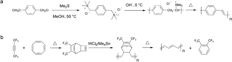 | ||
| Fig. 4 The Wessling (a) and the Durham (b) route to respectively PPV and PA. | ||
Initially the potential of the precursor route was not realised and it was dismissed in the middle of the 1990s77 when soluble PPVs were made via the Wessling route. New methods appeared that avoided some of the problems of the early Wessling method that involved an ionic precursor polymer. This was then quickly replaced by the Gilch81,82 and sulfinyl polymerisation types83–85 which are similarly precursor routes to PPV but they do not involve ionic precursors. In addition transition metal catalyzed cross couplings entered the scene and were employed in polymerisations of prototypical materials such as P3HT using the Rieke86,87 or the McCullough88 route. Today, virtually all of the known transition metal catalyzed organic chemical reactions have been employed for the polymerisation of conjugated materials (Stille, Heck, Suzuki etc.). The development was at that point in time (1995–2005) driven by the desire to be able to engineer new materials and generate new chemical structures. The development did thus not pay attention to the needs for the polymer photovoltaic technology but only focussed on the materials development and employed a standard polymer solar cell scheme for materials evaluation (i.e. glass, ITO, PEDOT, evaporated metal back electrodes). Especially the transition metal catalyzed methods do sometimes introduce an often neglected problem of residual catalyst in the form of metallic nanoparticles in the polymer products. While it is easy to miss the presence of sub percent quantities of metallic nanoparticles (e.g. palladium) in a conjugated polymer product the consequences when applied in an electroactive device may be severe.89 Methods to detect and remove the transition metal impurities have however been developed.90–92 As the field of polymer solar cells have developed more focus has recently been placed on materials properties and purity. The interplay between the device film preparation methodology and the device performance became broadly known in 200547,48 and it was found that the device performance ultimately hinges on parameters such as the solvents used for film processing, the nature of the materials (molecular weight, polydispersity), the method of film formation (coating/printing technique, drying time) and treatments of the device film post formation (thermal annealing, solvent annealing). The route to a high performing device from a particular material thus follows a hair fine path where any deviation may lead to poor performance.
Thermocleavable materials (solution-processable precursors)
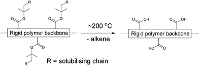
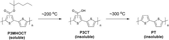
One route, taking the above mentioned issues into consideration, could be exploring the many possibilities in employing a conjugated material that is either reached through a precursor route or through a route where sidechains are removed post film formation. One can view these materials as bringing an extra dimension into the optimisation scheme where the device film in addition to thermal annealing and solvent annealing can be altered chemically. Both precursor and thermocleavable sidechain routes follow chemical reactions whereby a part of the material that constitutes the formed film is removed (sometimes up to 50% or more of the film weight or volume). The possibilities that thermocleavable materials have to offer warrant exploitation and certainly house the potential for bringing polymer solar cells to a more advanced level through materials design. To make polymer materials solution-processable, the introduction of solubilising groups is required. This is normally achieved by attaching solubilising side chains such as alkyl groups onto the conjugated polymer backbone. However, typical nonconjugated solubilising groups reduce the density of chromophores in the polymer and do not contribute to light harvesting and charge transport. Furthermore, the side chains make the material soft and allow for both morphological changes and diffusion of small molecules and constituents.93–96 The softness provided by alkyl groups is related to the instability of polymer solar cells, and more rigid systems have proven to give devices with a better stability.93 From this point of view, it is of some interest to prepare polymer solar cells via solution processing where it is possible to remove the solubilising side chains after the active layer has been deposited.The application of thermocleavable materials fulfils this requirement. With thermocleavable materials you exploit the instability of a bond in the molecule. The labile bond functions as the linker between the solubilising group and the active material. The most recent developments are the thermocleavable ester groups and the dithiocarbamate precursor route. With regard to the thermocleavable ester groups the solubilising group is typically a branched alkyl chain attached to the active conjugated polymer backbone through an ester bond (Fig. 5). When heated this bond breaks, eliminating a volatile alkene and leaving the polymer component insoluble. The thermal treatment can be viewed as a way of performing an in situ chemical reaction thereby allowing for the alteration of both physical and chemical properties such as solubility, hardness, hydrogen bonding, polarity, density and ionicity after the final device film has been prepared. In terms of stability and operational lifetime polymer solar cells generally perform poorly. It was however demonstrated that heterojunction devices based on poly-3-(2-methylhexan-2-yl)-oxy-carbonylbithiophene (P3MHOCT) and C60 can provide very stable behaviour after thermal elimination of the solubilising groups.93 The device film is prepared with standard solution processing methods followed by a thermal treatment around 200 °C (Fig. 6) where P3MHOCT eliminates the solubilising group as 2-methylhexene.
 | ||
| Fig. 5 Thermocleavable ester groups attached to the polymer backbone. After a thermal treatment around 200 °C the solubilising groups are eliminated. | ||
 | ||
| Fig. 6 Preparation of PT via a thermolytic reaction. | ||
After the thermal treatment P3MHOCT is converted to the more rigid and insoluble poly-3-carboxydithiophene (P3CT) which significantly improves the stability of the solar cell. The improved stability of this system has been linked to the rigid nature, cross-linking through a hydrogen-bonded network (Fig. 7) and a partially oxidized state.97
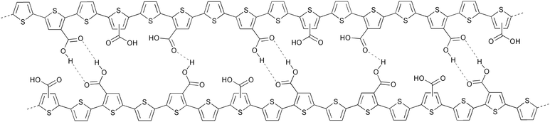 | ||
| Fig. 7 Proposed cross-linked structure of P3CT through a hydrogen-bonded network. | ||
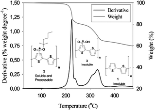
Furthermore, in the case of carboxylic esters attached to thiophenes, the processing offer removal of the esters at lower temperatures and the acid groups at higher temperatures allowing for multistep processing.98 Thermogravimetric data for P3MHOCT in the temperature range 25–475 °C shows two distinct weight loss mechanisms. The first weight loss at ∼200 °C accounts for the ester cleavage and the second weight loss at ∼300 °C is decarboxylation (Fig. 8). During the annealing, it is possible to visually see the color change of the sample from red to orange (conversion from P3MHOCT to P3CT) and then from orange to purple-red (conversion from P3CT to PT) (Fig. 9a). The UV-vis absorption spectra of P3MHOCT and [60]PCBM or [70]PCBM mixtures are shown in Fig. 9b. It shows a significant change of the absorption coefficient at different temperatures. In addition a small red shift of the peaks (at 500 nm) can be seen when the samples were heated up to 310 °C.
 | ||
| Fig. 8 Thermogravimetric data for P3MHOCT in the temperature range 25–475 °C. Reprinted with permission from ref. 98. © 2007 American Chemical Society. | ||
![(a) A photograph showing the appearance of films based on P3MHOCT:[70]PCBM when heated to different temperatures. (b) UV-vis spectra of films based on P3MHOCT and [60]PCBM or [70]PCBM mixtures spincoated on glass slides and annealed at three different temperatures (25, 250, and 310 °C). (c) Efficiency versus annealing temperature for bulk heterojunctions based on P3MHOCT and [60]PCBM/[70]PCBM. Reprinted with permission from ref. 99. © 2008 American Chemical Society.](/image/article/2010/JM/b913168j/b913168j-f9.gif) | ||
| Fig. 9 (a) A photograph showing the appearance of films based on P3MHOCT:[70]PCBM when heated to different temperatures. (b) UV-vis spectra of films based on P3MHOCT and [60]PCBM or [70]PCBM mixtures spincoated on glass slides and annealed at three different temperatures (25, 250, and 310 °C). (c) Efficiency versus annealing temperature for bulk heterojunctions based on P3MHOCT and [60]PCBM/[70]PCBM. Reprinted with permission from ref. 99. © 2008 American Chemical Society. | ||
This finding offers a route to native polythiophene (PT) by solution processing which has not been possible before. A plot of the power conversion efficiency, for P3MHOCT:PCBM devices, compared to the annealing temperature shows some interesting results.99 The power conversion efficiency of the bulk heterojunctions at room temperature was in the range 0.7–0.9% and was found to decrease as the device film was annealed at temperatures below the cleavage temperature (∼200 °C) of P3MHOCT to P3CT. After the transformation to P3CT a broad minimum is reached with power conversion efficiencies in the range 0.1–0.4%. When reaching the temperatures of the second transformation (∼300 °C) from P3CT to PT, a dramatic increase in power conversion efficiency was observed. Up to 0.6% in the case of [60]PCBM and as high as 1.5% in the case of [70]PCBM as shown in Fig. 9c. Clearly the morphology is changing with the chemical transformations and this is part of the explanation to the variable power conversion efficiency of this system. Another part of the explanation is the change in energy levels as the electron withdrawing carboxylic acid groups are removed from the conjugated polythiophene backbone. The use of thermocleavable conjugated polymer materials in polymer solar cells has been relatively limited due to the low performance observed when preparing devices from them. The preparation of efficient devices from native polythiophene via a thermocleavable route should be seen as the first breakthrough in the use of thermocleavable materials for polymer solar cells.98,99 The parameter space is enormous and the added complexity of thermocleavable materials (both their synthesis and processing into devices) combined with perhaps a poor starting point have resulted in a small investment in them in terms of research effort. The fact that efficiencies approaching 2% can be reached shows that it is not impossible to prepare efficient polymer solar cell devices from thermocleavable materials and it is interesting to speculate how far thermocleavable materials could have been pushed pending the same investment of research effort that has gone into materials such as MEH-PPV or P3HT.
The use of cleavable P3MHOCT in thin film devices was first introduced by Liu et al.100 The idea, besides improving the chromophore density, was to enable the interaction at the interface between the polymer and TiO2 in a (FTO/TiO2/P3CT/P3HT/Ag) photovoltaic cell (FTO = fluorine doped tin oxide). The device showed a 3-fold improvement in photocurrent compared to a reference cell without P3CT (Fig. 10). Under illumination the FTO/TiO2/P3CT/P3HT/Ag cell had an external quantum efficiency (EQE) of 12.6% and a power conversion efficiency of 1.10%, while the reference cell (FTO/TiO2/P3HT/Ag) had an EQE of 4.2% and a power conversion efficiency of 0.69%. The improvement in photocurrent/performance upon introduction of the P3CT layer may be related to several factors. Cleaving the solubilising groups results in higher chromophore density and the chelation of –COOH groups in P3CT to the TiO2 may enhance the interfacial charge-transfer efficiency.
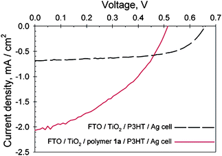 | ||
| Fig. 10 J–V curves of a FTO/TiO2/P3CT/P3HT/Ag cell (solid line) and a FTO/TiO2/P3HT/Ag cell (dashed line) under 39 mW/cm2 514 nm illumination. Reprinted with permission from ref. 100. © 2004 American Chemical Society. | ||
Other thermocleavable materials exploited as semiconductors are the dithiocarbamate precursors. Poly-(2,5-thienylene vinylene) (PTV) has been synthesised via the dithiocarbamate precursor route which exploits the lability of the linking thiocarbamate bond in the molecule (Fig. 11).101–105 The solution-processable non-conjugated precursor polymer is cleavable around 160 °C leaving a rigid conjugated polymer (PTV). Bulk-heterojunction solar cells based on blends of the precursor PTV and PCBM have demonstrated power conversion efficiencies of up to 0.76% after the thermal treatment.102
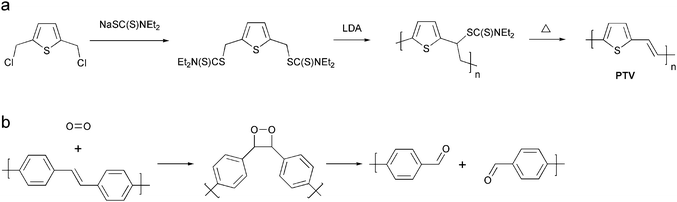 | ||
| Fig. 11 (a) Preparation of PTV via the dithiocarbamate precursor route (b) Reaction of the vinylene bond in a PPV polymer with singlet oxygen. Singlet oxygen adds to the vinylene bond forming an intermediate dioxetane followed by chain scission. The aldehyde products shown can react further with oxygen. | ||
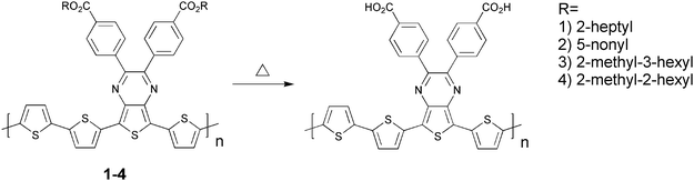
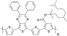
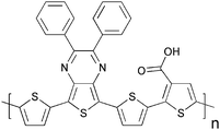
In terms of stability PTV is like PPV,106 sensitive to oxygen due to the vinylene groups that are susceptible to photo-oxidation resulting in a short lifetime of the devices. The chemical degradation is initiated by the formation of singlet oxygen by energy transfer from the photoexcited polymer to ground state oxygen molecules.107 The singlet oxygen can then react with the vinylene groups through a 2 + 2 cycloaddition reaction forming an intermediate dioxetane (Fig. 11) while other reactions are also possible. Finally the dioxetane can break down resulting in chain scission. As mentioned above more rigid systems generally give devices with a better stability and therefore improved stability of PTV devices prepared with the dithiocarbamate precursor route may be expected. The use of thermocleavable materials offers several advantages in the context of polymer solar cells. Most importantly the side chains that constitute a significant proportion of the final film are eliminated and ideally the final film comprises only the active component. Since bulk heterojunctions of polymer and PCBM are not directly compatible with the high temperatures acquired for elimination one aim is to achieve as low a temperature of elimination as possible. This has been investigated by Petersen et al. for thermocleavable esters of low band gap monomers and polymers based on diphenyldithienylthienopyrazine (Table 1).108 The temperature of elimination of a series of different ester groups was studied with thermogravimetric analysis (Fig. 12a).
|
|
||||||
|---|---|---|---|---|---|---|
| Polymer | J sc (mA/cm2) | V oc (V) | FF | PCE (%) | Cleaving temp. (°C) | Solubility in DCB |
| 1 | 1.52 | 0.14 | 0.25 | 0.05 | Uncleaved | Easy to dissolve |
| 0.41 | 0.16 | 0.26 | 0.017 | 310 | ||
| 2 | 2.1 | 0.4 | 0.29 | 0.25 | Uncleaved | Hard to dissolve |
| 0.36 | 0.14 | 0.27 | 0.013 | 310 | ||
| 3 | 2.55 | 0.41 | 0.29 | 0.3 | Uncleaved | Easy to dissolve |
| 0.24 | 0.08 | 0.26 | 0.005 | 310 | ||
| 4 | 2.4 | 0.46 | 0.36 | 0.4 | Uncleaved | Easy to dissolve |
| 1.94 | 0.4 | 0.33 | 0.25 | 230 | ||
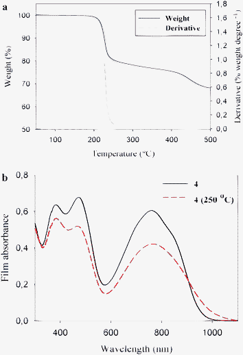 | ||
| Fig. 12 (a) Thermogravimetric data for polymer 4 (see Table 1) in the temperature range 50–500 °C. (b) UV‐vis absorption spectra of polymer 4 in thin film before and after thermocleavage. Reprinted with permission from ref. 108. © 2008 American Chemical Society. | ||
It showed that the thermal treatment is limited to simple secondary and tertiary esters where the alcohol is saturated in order to ensure that the alkene that is eliminated is removed efficiently without undesired side reactions.
As expected the tertiary esters eliminated at the lowest temperatures (200–250 °C) and even lower cleavage temperatures should be possible. The UV-vis absorption spectra of polymer 4 in thin film are shown in Fig. 12b. Upon thermocleavage of the film by heating it at 250 °C for 1 min the absorption spectrum shows a less intense absorption and a smaller band gap (1.2 eV) compared to the uncleaved film (1.3 eV). The lower absorption intensity can be explained by the associated change in film thickness and dielectric constant which may lead to changes in the reflection phenomena.108 In addition, the intensity of absorption quite often decreases as the band gap is lowered. In contrast to P3MHOCT where the ester resides on a thiophene ring, decarboxylation does not take place ahead of decomposition for the diphenyldithienylthienopyrazines. Table 1 also shows photovoltaic parameters of polymers 1–4 before and after thermocleavage. A general observation is that the devices perform significantly worse after thermocleavage as indicated by a decrease in voltage and current. Polymers 1–3 require high cleaving temperatures (310 °C) which could be the reason for the drastic drop in performance compared to 4 that only shows a minor drop in performance. To compare with earlier reported photovoltaic parameters for P3MHOCT the performance dropped around 10-fold when cleaved to P3CT and then improved 15-fold when cleaved further to PT (Fig. 9). In addition to the thermocleavable materials described above other examples have been described in the literature. These are summarized in Table 2.


Cross-linking
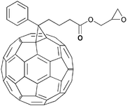
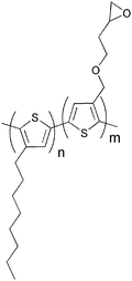
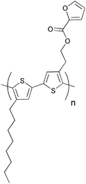
Several investigations of the most widely used bulk heterojunction of P3HT/PCBM with a special focus on thermal stability have shown a drastic drop in performance due to morphological changes where large aggregations of PCBM appear in the films upon prolonged thermal treatment.117–121 One way of approaching this problem has been by design of cross-linkable molecules/polymers (see Table 3) that can ‘lock’ the morphology and thus hinder the extensive phase separation. Zhu et al. and Drees et al. both succeeded in suppressing the aggregation by synthesising fullerene derivatives containing a glycidyl functionality (PCBG).122,123 Bulk heterojunctions of P3HT/PCBG cross-linked by Lewis acid catalysis showed enhanced morphological stability upon thermal annealing. Nevertheless, the efficiencies of the cells dropped considerably compared to the corresponding non-cross-linked P3HT/PCBM system. Zhu et al. also reports some initial attempts of using cross-linkable polymers with either epoxy- or furoyl containing side chains, that are cross-linked by use of a photoacid. The films are reported to be insoluble in THF, but no devices were prepared.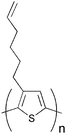
A more successful approach in preparing cross-linkable polymers have recently been reported by Myanishi et al.124 They have prepared a cross-linkable P3HT-analogue, poly(3-(5-hexenyl)thiophene) (P3HNT), where the hexyl group on thiophene is substituted with a 5-hexenyl. The polymer was prepared by polymerisation of 2,5-dibromo-3-(6-bromo-hexenyl) (regioregularity above 97% plus Mn and Mw/Mn values of 32![[thin space (1/6-em)]](https://www.rsc.org/images/entities/char_2009.gif) 000 and 1.30 respectively) followed by conversion of the 6-bromohexyl into the corresponding iodide. Finally basic elimination affords the desired compound (Fig. 13).
000 and 1.30 respectively) followed by conversion of the 6-bromohexyl into the corresponding iodide. Finally basic elimination affords the desired compound (Fig. 13).
 | ||
| Fig. 13 Polymerisation and side chain conversion reactions for the synthesis of P3HNT. | ||
The cross-linking process was performed by prolonged heating of the spincast films at 150 °C. Films prepared in this way showed enhanced insolubility in chloroform, and cross-linked bulk heterojunction films (P3HNT/PCBM) showed a suppressed deterioration of PCE after annealing for 10 h (3.03% before annealing →1.74% after annealing) compared to a corresponding P3HT/PCBM device (3.11% before annealing → 1.00% after annealing).
It should be mentioned that several attempts of cross-linking conjugated polymers have been reported in the context of organic light emitting diodes (OLEDs) with various degrees of success.125–131 Even though some of the polymers used in the OLED cross-linking experiments are different to those employed in solar cells, the methods of cross-linking the polymers could be relevant in the context of polymer photovoltaics.
Processing
The performance of polymer solar cells is intimately linked to the processing conditions during device preparation and when taking this further than the successful laboratory devices it is evident that the successful large scale preparation of polymer solar cells implies control over the interplay between process and device performance. The solutions to this puzzle for a chosen materials combination will have to be sought through the device geometry and the processing/fabrication method. Thermocleavable materials as an example have much to offer in the context of processing multilayered polymer solar cells industrially. When processing multilayer structures sequentially the processing of subsequent layers must ideally not affect the underlying layers and this is particularly important when using solution processing. The common way of solving this has been to use orthogonal solvents for adjacent layers. In the extreme case water is used as the solvent for the first layer and an organic solvent is used for the next layer. This has been the traditional way of making polymer solar cells based on a glass-ITO substrate where poly(3,4-ethylenedioxythiophene):poly(styrenesulfonate) (PEDOT:PSS) is spincoated onto the ITO from an aqueous dispersion followed by spincoating of the active layer from an organic solvent and completion of the device through evaporation of a metal back electrode. It is fortuitous that the standard laboratory polymer solar cell has only needed these two solution processed layers for several reasons. Firstly, the surface energy of a solid PEDOT:PSS film is higher than the surface tension of active materials in typical organic solvents making wetting easy. Secondly, additional layers would be faced with the problem of finding an additional solvent orthogonal to the two previously deposited layers. These two problems may seem trivial but they are at the heart of what has limited the early emergence of a low cost industrial and large scale process. The fact that the technology has evolved around fixed ingredients (i.e. glass, ITO, PEDOT:PSS, metal electrode) and fixed methods of application (i.e. spincoating, metal evaporation) implies that development has been slow towards alternative approaches such as ITO free and inverted device geometries that enables the use of printed electrodes. One way to obtain orthogonality between the processing conditions for subsequent layers is by transformation of the last processed layer into an insoluble film thus enabling free choice of processing conditions for the subsequent layers. This has been achieved unintentionally in the case of oxide layers such as zinc oxide and titanium dioxide employed in hybrid solar cells and can be achieved intentionally with thermocleavable materials where insolubility arises upon thermocleavage as detailed above. Deliberate use of thermocleavable materials has been shown in one development of a process for industrially processed polymer solar cells.132–135Hybrid solar cells
Hybrid solar cells (HSC) have a heterojunction consisting of both organic and inorganic materials, thus trying to combine the advantages of each of these. Polymers generally have high hole mobility but a low electron mobility, and this intrinsic carrier mobility imbalance in the polymer is overcome by incorporation of an n-type inorganic material to act as the electron acceptor and a pathway for electron transport. The efficiency of the heterojunction is limited by the exciton diffusion length as excitons formed at positions further away from an interface than the exciton diffusion length have a lower probability of efficient charge separation and harvesting. Efficient charge separation can only occur at the p–n interface and ideally the heterojunction should be constructed in a manner such that the excitons are generated in the vicinity of the interface. At the same time the constructed heterojunction should ensure a direct or percolating pathway of the charge carriers to the relevant electrodes in order to effectively transport and collect the charges. The semiconducting properties in HSC of several different inorganic materials have been examined with promising results, i.e. TiO2,136–145 ZnO,146–158 CdSe,159–164 CdS,165,166 PbS,167 PbSe,168 SnO2,169 and Si,170,171 as presented in Table 4. In recent years research has largely focused on the use of TiO2, ZnO and Si, mainly because of the environmental harmfulness and toxicity of many of the others. The choice of polymer used in HSCs has usually been P3HT or different PPV polymers as they have shown good hole conducting properties.| Inorganic semiconductor | Polymer | Architectural category | VOC(V) | JSC (mA/cm2) | FF | η(%) | Comments | Ref. |
|---|---|---|---|---|---|---|---|---|
| a Abbreviations: NP: nanoparticle; P: particle; Surf. mod.: surface modified. b APFO-3: poly(2,7-(9,9-dioctylfluorene)-alt-5,5-(4′,7′-di-2-thienyl-2′,1′,3′-benzothiadiazole)). | ||||||||
| CdSe | OC1C10-PPV | Tetra-pod NP | 0.76 | 9.1 | 0.44 | 2.8 | VOC and JSC were extracted from a figure | 162 |
| P3HT | Nanorod P | 0.62 | 8.79 | 0.50 | 2.6 | 163 | ||
| APFO-3b | Nanorod P | 0.95 | 7.23 | 0.38 | 2.6 | 164 | ||
| P3HT | Hyperbranched P | ∼0.6 | ∼7.0 | — | 2.2 | 159 | ||
| OC1C10-PPV | Tetra-pod NP | 0.65 | 7.3 | 0.35 | 1.8 | 161 | ||
| P3HT | Nanorod P | 0.7 | 5.7 | 0.4 | 1.7 | 160 | ||
| CdS | P3HT | Surf. mod. NP | 0.54 | 4.84 | 0.45 | 1.18 | Surf. mod. with a polyacetylene containing quaternary pyridinium salts | 165 |
| MEH-PPV | Multiarmed nanorod P | 0.85 | 2.96 | 0.47 | 1.17 | 166 | ||
| PbSe | P3HT | NP | 0.35 | 1.08 | 0.37 | 0.14 | 168 | |
| PbS | MEH-PPV | NP | 1 | 0.13 | 0.28 | 0.7 | AM 1.5 conditions but at low power (5 mW/cm2) | 167 |
| SnO 2 | MDMO-PPV | Surf. mod. nanoporous NP layer | 0.65 | 0.32 | 0.42 | 0.085 | Surf. mod. with C60C(COOH)2 | 169 |
| ZnO | P3HT/PCBM | Vertical nanorod array | 0.58 | 10.4 | 0.65 | 3.9 | Surf. mod. with N719 | 154 |
| P3HT/PCBM | Vertical nanorod array | 0.57 | 9.6 | 0.50 | 2.7 | 153 | ||
| P3HT/PCBM | Vertical nanorod array | 0.475 | 10 | 0.43 | 2.03 | 151 | ||
| P3HT/PCBM | Surf. mod. vertical nanorod array | 0.57 | 8.89 | 0.41 | 2.0 | 155 | ||
| MDMO-PPV | NP | 0.81 | 2.4 | 0.59 | 1.6 | 146 | ||
| P3HT | In situ prepared | 0.83 | 3.3 | 0.50 | 1.4 | Diethylzinc as ZnO-precurser | 150 | |
| MDMO-PPV | In situ prepared | 1.14 | 2.0 | 0.42 | 1.1 | Diethylzinc as ZnO-precurser | 147 | |
| P3HT | Vertical nanorod array | 0.44 | 2.17 | 0.56 | 0.53 | Surf. mod. with mercurochrome | 152 | |
| P3HT | Surf. mod. vertical nanorod array | 0.46 | 2.45 | 0.46 | 0.52 | 149 | ||
| APFO-3b | NP | 0.51 | 3.1 | 0.36 | 0.45 | 156 | ||
| Si | P3HT/PCBM | Vertical nanowires | 0.43 | 11.6 | 0.39 | 1.93 | 170 | |
| P3HT | NP | 0.75 | 3.3 | 0.46 | 1.15 | 171 | ||
| TiO 2 | P3HT | Surf. mod. nanorod P | 0.78 | 4.33 | 0.65 | 2.20 | Surf. mod. with N3-dye | 141 |
| P3HT | Surf. mod. nanorod P | 0.75 | 3.49 | 0.65 | 1.70 | Surf. mod. with anthracene-9-carboxylic acid | 140 | |
| P3HT | Nanorod P | 0.64 | 2.73 | 0.56 | 0.98 | 142 | ||
| P3HT | Nanorod P | 0.52 | 2.97 | 0.54 | 0.83 | 144 | ||
| MEH-PPV | Bilayer | 1 | 1.8 | 0.37 | 0.67 | 136 | ||
| P3HT/PMMA | Nanorod P | 0.53 | 2.57 | 0.48 | 0.65 | 143 | ||
| P3HT | Vertical nanorod array | 0.32 | 3.89 | 0.41 | 0.51 | 139 | ||
| P3HT | Surf. mod. nanofiber mat | 0.57 | 1.27 | 0.40 | 0.29 | Surf. mod. with N719-dye | 145 | |
| P3HT | Surf. mod. nanoporous NP layer | 0.64 | 1.11 | 0.34 | 0.24 | Surf. mod. with N3-dye | 138 | |
| MEH-PPV | Vertical array of hexagonal pores | 0.79 | 0.56 | 0.47 | 0.21 | 137 | ||
| P3HT | Surf. mod. bilayer | 0.46 | 0.67 | 0.48 | 0.15 | Surf. mod. with black dye | 138 | |
| ZnO + TiO 2 | P3HT | Vertical ZnO nanorod array + TiO2 nanorod P | 0.49 | 2.67 | 0.45 | 0.59 | 148 |
Various approaches in HSC design have been explored and they generally fall into 4 architectural categories:
(1) planar bilayer;
(2) nanoparticle/polymer blends;
(3) in situ generation of the n-type inorganic in the polymer;
(4) nanostructured: infiltrating rigid nanoporous or nanorod structures with a polymer.
The schematic representation of these is shown in Fig. 14.
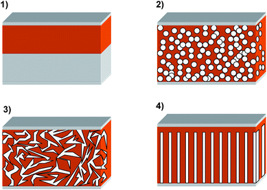 | ||
| Fig. 14 The different geometries of hybrid solar cells: (1) Planar bilayer—the polymer added onto a flat inorganic surface; (2) nanoparticle/polymer blends—a mixture of the polymer and suspended inorganic particles is applied; (3) in situ generation of the inorganic within the polymer—a mixture of the polymer and a soluble precursor to the inorganic is applied and solidification of the inorganic is then performed after film preparation; (4) nanostructured—a rigid nanoporous or nanorod structure of inorganic is filled with the polymer. | ||
Covering a planar layer of inorganic semiconductor with a polymer film is the most direct approach to a hybrid solar cell, but the design has limited application as the active layer of polymer has to be very thin in order to make use of all the excitons. The simplicity of the architecture though renders it very applicable for routine evaluation of the properties of new polymers and measurement of exciton diffusion lengths.
When using nanoparticle/polymer blends the active layer is normally prepared by spincoating a solution containing dissolved polymer and suspended nanoparticles, thus enabling deposition of both semiconductors in a single step. The procedure should in principle ensure intimate mixing of the acceptor and donor, but great care must be taken in tuning the surface chemistry of the nanoparticles in order to prevent these from aggregating and at the same time ensuring a good interface for charge transfer.172 Nanoparticle aggregation is believed to be one of the limiting factors of the efficiency in nanoparticle/polymer devices.173
Examples of this include the use of tetrapod, hyperbranched and nanorod CdSe nanoparticles in combination with conjugated polymers where efficiencies are approaching 3%.159–164 Essential for the good performance is to replace the nanoparticle surface ligands with a volatile molecule (for example replacement of tri-n-octylphosphine oxide with pyridine), allowing for evaporation of the surface ligands during film processing. This again allows for better contact between the polymer and the nanocrystals and between the individual nanoparticles.
In one example Beek et al. have achieved a PCE of 1.6% and avoid the problem of surface ligands by using crystalline ZnO nanoparticles, which are soluble in organic solvents and therefore can be mixed directly with the polymer.146,147
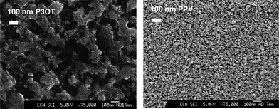
An alternative approach to individual nanoparticles was introduced by van Hal et al. that prepared a continuous interpenetrating network of TiOx created in situ within the conjugated polymer film after spincoating a mixture of MDMO-PPV and a precursor for TiOx (Ti(OC3H7)4).174 Subsequent exposure of the cast film to moisture from the air led to the formation of a TiOx network. The photoluminescence (PL) of the MDMO-PPV:TiOx heterojunction was significantly quenched compared to a pristine MDMO-PPV film (PL is reduced by a factor 19 with a 50% w/w content of TiOx) indicating an efficient charge separation of photoinduced excitons. These experiments were later confirmed by Slooff et al. where additional experiments were performed with poly(3-octyl thiophene) (P3OT) as the polymer.175 Scanning electron microscopy (SEM) images taken after removal of the polymers by UV–ozone treatment revealed TiOx phases with sizes on the order 100–200 nm for P3OT blends and 20–30 nm for MDMO-PPV blends. The difference is assumed to be caused by the tendency of P3OT to aggregate more easily as compared to MDMO-PPV (Fig. 15).
 | ||
| Fig. 15 SEM of the TiOx phase after removal of the polymer by UV–ozone treatment for 10 min. Left: from a P3OT:TiOx (12 vol% TiOx) blend. Right: from a MDMO-PPV:TiOx(14 vol% TiOx) blend. Reprinted with permission from ref. 175. © 2003 Elsevier B.V. | ||
Despite the good interpenetrating network of TiOx, photovoltaic devices showed rather low power conversion efficiencies which is ascribed to the fact that the inorganic phase is essentially amorphous.147 Crystallisation of TiOx into the anatase phase of TiO2 would require high temperatures (>350 °C).176
A similar approach was taken by Beek et al. using MDMO-PPV and diethylzinc as a ZnO precursor.147 ZnO is known to crystallise at much lower temperatures than TiO2, and heating to 110 °C under nitrogen at 40% relative humidity promoted crystallisation. The final device gave a PCE of 1.1%. Moet et al. later reported partial degradation of the polymer during processing of MDMO-PPV and diethylzinc and that P3HT (no vinyl groups) show better stability and higher performance (PCE 1.4%).150
The last architectural approach involves the filling of a pre-created inorganic nanostructure (vertical structured nanopores or vertically oriented nanorods/nanopillars) with a polymer (examples are given in Fig. 16). The aim is to create a structure where the separation of the phases is in the order where complete exciton harvesting and charge collection is possible and where the straight pore/channel network provides the most direct pathway for the charges to the anode and cathode. Several techniques137,139,170,177–181 have been developed in order to create controlled structures pursuing the alleged optimal conditions. Among the published results on solar cells Olson et al. reported the fabrication and characterisation of heterojunctions consisting of P3HT and a mesoporous structure of ZnO nanofibers.152 The nanofibers were grown hydrothermally on a glass/ITO substrate which was subsequently filled with P3HT by spincoating and annealed to ensure intercalation into the voids between the nanofibers. The final device showed a 3.5 times increase in PCE (to 0.53%) compared to the corresponding bilayer device of P3HT on planar ZnO.
Kuo et al. recently showed good results for ordered heterojunctions with vertically aligned TiO2 nanorods and P3HT.139 The vertical TiO2 nanorods were prepared by spincoating a TiO2 precursor into the pores of an aluminium anodic oxide (AAO) template pregrown on an ITO/glass substrate. After sintering, the AAO template was removed by dissolving it in aqueous NaOH. The nanorods are approximately 200 nm long and with a diameter 30–60 nm. The resulting solar cell after spincoating of P3HT and annealing showed to be 4.3 times more efficient (PCE of 0.51%) than planar TiO2:P3HT.
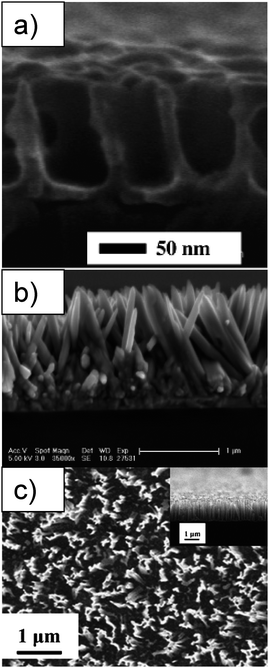 | ||
| Fig. 16 SEM images of (a) cross sectional view of embossed TiO2 structures on FTO substrate after calcinations. Reprinted with permission from ref. 178. © 2005 American Chemical Society. (b) ZnO nanorods grown on dense ZnO backing layer on ITO substrate (cross section). Reprinted with permission from ref. 181. © 2006 American Chemical Society. (c) Top view of Si-nanowires on silicon wafer prepared by wet etching, with an insert of the cross sectional view. Reprinted with permission from ref. 170. © 2008 Elsevier B.V. | ||
As can be seen from Table 4, several of the reports with the highest efficiencies are reported for P3HT/PCBM blends and an inorganic semiconductor. The inorganic material here functions as an extra electron carrier. Takanezawa et al. showed that incorporation of the P3HT/PCBM bulk heterojunction into a vertical ZnO nanorod array led to an increase in PCE from 1.8% for a normal P3HT/PCBM heterojunction on top of a seed layer of ZnO to a PCE of 3.9% when growing the seed layer to nanorods with a length of 300 nm before spincoating the P3HT/PCBM solution.153,154 As seen in Fig. 17 the ZnO rods can act as an extra electron carrier at the p–n interface with P3HT but can also operate as an intermediate between PCBM and ITO.
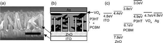 | ||
| Fig. 17 (a) FE-SEM cross-section image of the ZnO nanorod arrays (scale bar: 300 nm), (b) schematic structure of a ZnO/organic hybrid device with a VOx buffer layer, and (c) energy diagram of the ITO/ZnO/PCBM:P3HT/VOx/Ag device. Reprinted with permission from 154. © 2008 American Institute of Physics. | ||
Another tendency in Table 4 that leads to relatively high efficiencies is the use of the surface modified inorganics, typically with a dye that can assist in charge separation and prevents back recombination. (For all results involving surface modification presented in Table 4 the concentration of the interfacial molecules is so small that they only have a minimal or negligible contribution to the light absorption, and the polymer is thus the main contributor to absorption.) Lin et al. have recently demonstrated that surface modification by ligand exchange of the surface ligands of freshly prepared nanorods (∼20–30 nm in length and 4–5 nm in diameter) with different dyes led to improved performances compared to ‘normal’ ligand exchange with pyridine, a near doubling of the PCE (from 1.12% to 2.20%) was observed in a HSC with P3HT.141 The authors ascribe the large increase in PCE to be partially an effect of enhanced charge separation but mainly to be attributed to a strong suppression of back transfer and recombination of carriers at the interfaces. In Fig. 18 the energy diagram of TiO2, the dye ligands, and P3HT are shown. All the dyes showed improved performance when used as surface modifiers in the order N3 (2.20%) > CuPc (1.80%) > ACA (1.67%).
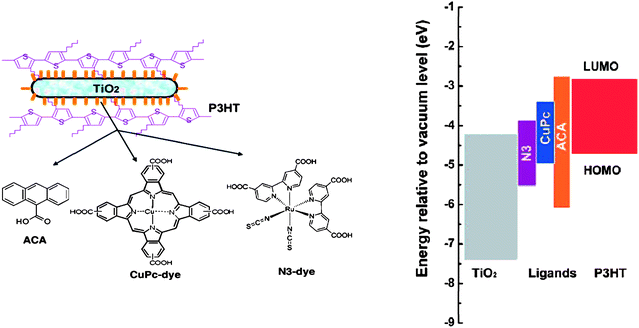 | ||
| Fig. 18 Left: Schematic representations of P3HT/TiO2 nanorod hybrid after interface modification and chemical structures of different interfacial molecules of ACA, CuPc-dye, and N3-dye molecules respectively. Right: The corresponding energy levels of the various materials. Reprinted with permission from ref. 141. © 2009 American Chemical Society. | ||
The results for the P3HT/PCBM:n-inorganic and the use of surface modified inorganics show that ‘tuning’ the charge separation and back recombination by adding a third component might be a promising path for future research. The third component is typically added at the interface between the inorganic semiconductor and the polymer vis-à-vis the well known dye sensitized solar cells where it serves the purpose of facilitating charge injection from the polymer to the semiconductor while preventing back recombination.
Tandem cells
So far the power conversion efficiency of single bulk heterojunction solar cells has reached 6% while higher power conversion efficiencies are possible from a theoretical point of view. One drawback of single junction polymer devices is their narrow absorption window compared to the solar cells based on inorganic semiconductors. A possible approach to efficiently harvest light at both short and long wavelengths is by stacking different band gap materials/devices on top of each other. This can be done by placing the cells in series giving devices known as tandem cells.1,13,14 By stacking different band gap materials on top of each other the tandem cell should be able to exceed the maximum theoretical efficiency of a single junction solar cell because it increases the absorption of solar light and allows exploiting the photon energy more efficiently. When two cells (in a two terminal tandem cell) are connected in series the open-circuit voltage (Voc) is the sum of the Voc's of the subcells, Voc1 + Voc2 + Voc3… = Voc (tandem).Fig. 19 illustrates a typical organic tandem cell architecture comprised of two distinct active layers stacked on top of each other. Both of them are based on a donor–acceptor composition and the use of materials with different band gaps enables absorption of solar light over a wider spectral range. Typically a material with a wide band gap is used for the first cell and a low band gap material is used for the second cell. In order to prevent charge build-up within the cells a transparent intermediate layer is positioned between the two active layers. The intermediate layer ensures recombination of the electrons created in the first cell with the holes created in the second cell. In addition, it can act as a protective layer to support the bottom cell during deposition of the top active layer. This can generally be accomplished with a thin inorganic layer. Several methods have been employed in the fabrication of tandem cells depending on the materials used for the active and the intermediate layer. The mode of preparation can be divided in three categories: all vacuum processing by evaporation of low molecular weight molecules, a combination of vacuum and solution processing and all solution processing. Due to the complexity of multilayer solution processing caused by interlayer mixing, the early reports of organic tandem cells are based on the vacuum deposition of small molecules and they certainly show increased Voc and efficiencies.182–186 Also a combination of vacuum and solution processing is a fine approach where the solution processed underlying layer is not disturbed during subsequent vacuum processing.187–190 However, from an industrial point of view, all solution processing without the use of vacuum where each layer is processed from solution (including the metal electrode) is the most appealing because techniques like ink-jet printing, screen printing and roll-to-roll coating are less time and energy consuming and enable large scale organic solar cell production. Gilot et al. were the first to demonstrate a polymer tandem cell with each layer processed from solution (the metal electrode was evaporated).191
 | ||
| Fig. 19 Typical device setup for an organic tandem cell. | ||
The technique relies on the choice of solvent for the different layers. They have to be complementary in the sense that the next solvent in the process is not affecting the material in the underlying layer. Fig. 20 illustrates the device setup realized by Gilot et al. The challenging step is the spincoating of the intermediate layer where the authors used a layer of zinc oxide nanoparticles spincoated from acetone prior to a layer of pH neutral PEDOT. The ZnO/PEDOT recombination layer was not affecting the underlying active layer of MDMO-PPV:PCBM and was also acting as a protective layer to support the bottom cell during deposition of the second active layer consisting of a P3HT:PCBM bulk heterojunction. The solution processed tandem cell has led to an efficiency of 6.5% for a polymer solar cell with an evaporated metal back electrode.192 It was demonstrated by Kim et al. with a bulk heterojunction composite of PCPDTBT (Fig. 1) and PCBM for the bottom cell and a layer of P3HT:[70]PCBM for the top cell. For the intermediate layer the authors used a layer of TiOx spincoated from a TiOx precursor solution (sol–gel chemistry)193 prior to a layer of PEDOT. The TiOx precursor hydrolyses to TiOx during 1 hour in air (Fig. 21) and the final TiOx layer offers high mechanical stability to the tandem cell. The final polymer tandem cell showed an improvement of 38% in performance versus the best single cell.
 | ||
| Fig. 20 Device setup for the tandem solar cell realized by Gilot et al. | ||
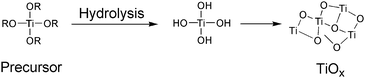 | ||
| Fig. 21 Preparation of the TiOx layer. | ||
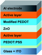
An all solution processed tandem polymer solar cell based on thermocleavable materials has been reported by Hagemann et al.109 The authors used solution-processable precursors that allow for conversion to an insoluble state by a thermal treatment. A bulk heterojunction composite of P3MHOCT and ZnO was used for the bottom cell and a blend of poly-[(3′-(2,5,9-trimethyldecan-2-yl)-oxy-carbonyl)-[2,2′;5′,2″]terthiophene-1,5″-diyl)-co-(2,3-diphenylthieno[3,4-b]pyrazine-5,7-diyl)] (P3TMDCTTP) and ZnO was used for the top cell (Fig. 22). Straight after each film preparation a short thermal treatment eliminated the solubilising group converting P3MHOCT to P3CT and P3TMDCTTP to P3CTTP. To separate the bottom cell from the top cell an intermediate layer of PEDOT:PSS and ZnO were used. The final tandem cell performed relatively poorly but did not involve the use of fullerenes and efficiently solved the problems associated with solubility during application of subsequent layers. In addition a solution processed metal electrode was employed. An obvious advantage of thermocleavable materials is that they offer new levels of processing after film forming. Due to the insoluble nature of the active materials after the thermal treatment there is no limit in the choice of solvents when processing the subsequent layers in the tandem cell and more research into this field appears worthwhile.
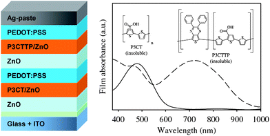 | ||
| Fig. 22 Tandem solar cell based on thermocleavable materials realized by Hagemann et al. The active layer film absorption spectra are also shown with P3CT/ZnO plotted with a solid line and P3CTTP/ZnO plotted with a broken line. Reprinted with permission from ref. 109. © 2008 Elsevier B.V. | ||
Recently a novel concept was introduced whereby the tandem solar cell is realized in a reflective geometry where the reflected light of one cell is directed towards the second one.194–197 Tvingstedt et al. demonstrated that by folding two planar cells with different band gap materials toward each other, spectral broadening and light trapping are combined to give an improvement of PCE from 2% up to 3.7% upon folding from 0° to 70° (Fig. 23).196 A bulk heterojunction composite of APFO3 and PCBM was used for one cell and APFO-Green9:PCBM for the second cell. The advantage of the folded tandem device is that it avoids complex multilayer solution processing and other problems related to multijunction stacking
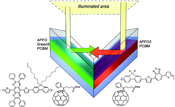 | ||
| Fig. 23 Folded tandem cell realized by Tvingstedt et al. Sketch of the folded tandem cell and the chemical structures of the exploited alternating polyfluorenes APFO3, APFO Green-9, and the acceptor molecule PCBM. Reprinted with permission from ref. 196. © 2007 American Institute of Physics. | ||
Control of the nanomorphology
The nanoscale morphology is an important factor in the construction of functional organic bulk-heterojunction solar cells as it is of interest to be capable of controlling the dimension of the domains in the nanostructure such that all domain boundaries are within the exciton diffusion range in the photoactive layer. Han et al. have demonstrated a novel procedure to create morphologically controlled nano/microscale patterns of π-conjugated polymers.114 An acidic mixture of polyfluorene or polythiophene bearing solubilising thermocleavable tetrahydropyranyl (THP) groups, and poly(methyl methacrylate) (PMMA) is used for the active layer. After spincoating on substrates phase separation is induced by the chemical dissimilarity of the two polymers giving rise to a nano/microscale morphology. After an acid catalyzed thermal treatment where the THP groups are eliminated the insoluble conjugated polymer remains (Fig. 24). Subsequently, PMMA is removed by treating the films with a chlorobenzene/hexane solution leaving a dot matrix of the conjugated polymer (Fig. 25).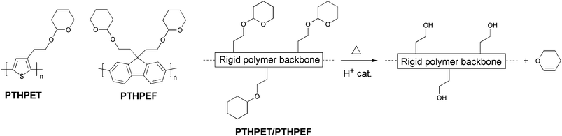 | ||
| Fig. 24 Thermocleavable polymers PTHPET and PTHPEF and acid-catalyzed elimination of dihydropyran from the polymer backbone. | ||
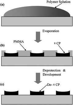 | ||
| Fig. 25 Schematic illustration of the formation of a well-ordered micro and nanometre-sized π-conjugated polymer features (PTHPET or PTHPEF) by (a) solution casting, (b) self-organization, and (c) catalytic reaction and development. Reprinted with permission from ref. 114. © 2007 WILEY-VCH. | ||
This method, where a template is used to control the nanostructure of conjugated polymers, has been exploited by Andreasen et al. in a solar cell context.198 Instead of PMMA, copper nanoparticles with an average diameter of 32 nm were used as the template to nanostructure a conjugated polymer based on P3MHOCT. Mixtures of P3MHOCT and the copper nanoparticles are processed into thin films followed by a thermal treatment whereby the solubilising side chains of the polymer were eliminated, leaving an insoluble film of conjugated P3CT with included copper nanoparticles. The copper nanoparticles could then be removed by treating the films with a THF solution of phenylazodiethylthioformamide (copper-specific solubilising agent90,91) leaving voids in place of the copper nanoparticles (Fig. 26). Finally the voids in the dried nanoporous films were filled with PCBM by doctorblading forming a donor–acceptor bulk heterojunction.
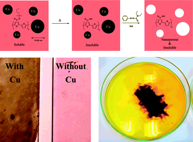 | ||
| Fig. 26 Reaction scheme for the process (above) and pictures of the films before and after removal of the copper nanoparticles. The film loaded with copper nanoparticles has a black appearance whereas the film where the copper nanoparticles have been removed had a red color (lower left). The dissolution step is also shown where a device slide (50 mm × 25 mm) is covered with a THF solution of azothioformamide. The dark color is due to the formation of the copper complex of azothioformamide (lower right). Reprinted with permission from ref. 198. © 2007 American Chemical Society. | ||
However, the nanostructures had little influence on the photovoltaic effect. The best device (active area of 3 cm2) had an open-circuit voltage of 0.43 V, a short-circuit current of 0.19 mA cm−2, a fill factor of 27.4%, and a power conversion efficiency of 0.02% (0.1–0.4% for P3CT:[60]PCBM). These data are much lower than the state-of-the-art and is ascribed to the low porosity of the films (<20%) and the large size of the PCBM domains. The ideal size of the PCBM domains should be of the order of 5–10 nm, and the porosity should be closer to 50% or more. This method may find importance in the modification of nanoscale morphologies for polymer solar cell devices if it could be advanced for incorporation of larger amounts of well-distributed smaller nanoparticles (5–10 nm) into the conjugated polymer film.
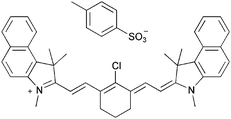
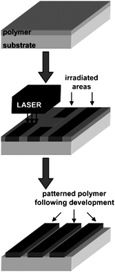
Laser-induced thermal patterning is another technique to control the morphology of conjugated polymers. Gordon et al. have developed a method for direct thermal patterning of a thermocleavable π-conjugated polymer film containing a near-infrared (NIR) sensitive dye.199 The NIR dye (Fig. 27) is incorporated directly into the polymer film by spincoating a NIR dye/polymer blend on a substrate.
When the film is exposed to NIR light pulses from an 830 nm laser beam the dye absorbs the irradiation and converts the NIR photons into heat by internal conversion. The polymer (PTHPET) does not absorb the NIR light. The heat produced by the dye induces thermocleavage of the THP groups. Subsequently, the NIR dye is removed by rinsing the films with methanol followed by THF leaving patterned π-conjugated polymer (Fig. 28). The patterned π-conjugated polymer shows a significant reduction in the quantum yield, compared to a pure PTHPET film, which is ascribed to either the presence of residual NIR dye remaining in the film after rinsing or/and coplanarisation and chain aggregation after thermocleavage of the THP groups.
 | ||
| Fig. 28 Schematic diagram for the direct thermal patterning of a π-conjugated polymer using a NIR laser realized by Gordon et al. Reprinted with permission from ref. 199. © 2007 American Chemical Society. | ||
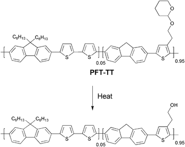
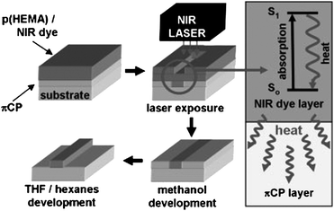
To overcome this problem novel strategies have been developed where the NIR dye is not incorporated into the film. Gordon et al. have described a bilayer approach,115 wherein a NIR dye is contained in a film of poly(2-hydroxyethylmethacrylate) [p(HEMA)] spincast onto a thermocleavable π-conjugated polymer film of poly(9,9-dihexylfluorene-alt-2-(2-thiophen-3-ethoxy)tetrahydropyran)-co-(9,9-dihexylfluorene-alt-bithiophene) (PFT-TT) (Fig. 29).
After exposure of the bilayer film to 830 nm NIR laser irradiation the p(HEMA)/NIR dye layer is removed by rinsing with methanol. Subsequent treatment of the remaining film with a THF/hexane solution removes non-cleaved PFT-TT (unexposed p(HEMA)/NIR dye regions) leaving a patterned π-conjugated polymer (Fig. 30). Using this bilayer film architecture the active conjugated polymer layer can be heated by exposure to NIR irradiation while minimizing deleterious mixing of the polymer with the NIR dye. Compared to the monolayer approach described above the π-conjugated polymer retains its photoluminescent properties showing quantum yields as high as 86% of the pristine polymer. The method is capable of imaging large surface areas, up to 1 m2, at relatively high throughput and with micrometre size resolution (typically 5–10 µm), and thus could be valuable in the context of processing of thermocleavable polymers for solar cells.
 | ||
| Fig. 30 Bilayer approach to laser induced direct thermal patterning of a π-conjugated polymer realized by Gordon et al. Reprinted with permission from ref. 115. © 2008 WILEY-VCH. | ||
ITO-freedom and advanced device concepts
The most commonly used transparent electrode in organic photovoltaics is based on indium-tin-oxide (ITO) which has the disadvantage of being rather expensive due to the scarcity of indium which is the main material in ITO by weight. In addition, the expanding market for optoelectronic devices could create a demand so high that securing a steady supply of indium might be problematic in the near future. This generates the need of new transparent semiconducting materials with good conductivity to minimize ohmic losses or new techniques/designs of devices. There has been relatively few reports on polymer solar cells that do not employ indium.200–208 Of these, three are directly relevant to industrial manufacturing processes.200,201,208 The wrap through concept is well known from 1st generation photovoltaics209 and has later been demonstrated to work well for polymer solar cells,208 and some of the ITO free polymer solar cell module concepts have been demonstrated to work in a full roll-to-roll process.200,201 For the latter though, the performance was significantly lower than what could be obtained using ITO based flexible substrates in a similar roll-to-roll process as shown in Fig. 31.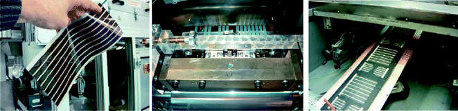 | ||
| Fig. 31 Roll-to-roll coated polymer solar cells using an ITO based process (left) and ITO-free processes (middle and left). | ||
An alternative approach to avoid the use of indium has been introduced by Niggemann et al.,210 who report the fabrication of a novel architecture in organic photovoltaic devices without the use of transparent electrodes and with extremely high voltages. Built on substrates of transparent lamellar nanostructured polymer, devices consisting of series of interconnected elementary cells (up to 1390 cells/mm) are prepared (Fig. 32). Anodes and cathodes are deposited on the vertical walls of the lamellas by thermal evaporation of titanium or MoO3 respectively from inclined incident angles, such that anode and cathode pairs of adjacent elementary cells are interconnected at the tip of the nanolamellae. The photoactive composite (P3HT/PCBM - 3:2) is then spincoated in the final process step.
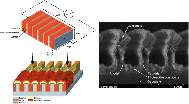 | ||
| Fig. 32 High voltage devices. Upper left: Basic sketch of a series interconnected photovoltaic nanomodule. An elementary cell is represented by the photoactive volume sandwiched between an anode and a cathode. Lower left: Schematic drawing of the series interconnected photovoltaic nanomodule. Anodes and cathodes are deposited on the walls of the nanolamellae by evaporation from an inclined incident angle. The series interconnection of adjacent elementary cells is carried out by overlapping the electrodes at the tips of the lamellae. In order to suppress charge carrier recombination, the tips of the nanolamellae are coated with a dielectric layer. The electrical contact is provided via two contact tips positioned onto the metallised nanolamellae. Right: SEM cross-section of a photovoltaic nanomodule. The tips of the lamellae are coated with lithium fluoride by thermal evaporation under inclined incident angles. Reprinted with permission from ref. 210. © 2008 Wiley-VHC Verlag GmbH & Co. KGaA, Weinheim. | ||
In order to suppress interconnection of adjacent cell elements by the photoactive composite, a dielectric layer of lithium fluoride was furthermore deposited at an angle on the tip of the lamellae prior to spincoating. Under AM1.5 illumination, a 17.4 mm × 7.9 mm photovoltaic nanomodule prepared in this way generated an open circuit voltage of 880 V and a short circuit current of 2 × 10⁻⁸ A. The solar power conversion efficiency is stated to be 0.008% when considering a fill factor of 25%. The concept of wrap through was first introduced in 1993 by Gee et al.209 for silicon based solar cells and have now been implemented in polymer based photovoltaics by Zimmermann et al.208 in order to avoid the use of transparent electrodes. The general idea behind wrap trough is to have both electrodes on the back side of the device, one having a traditional layered contact with the light absorber, and the other being connected to the absorber through a series of holes/channels, leading through the device, that have been filled with a highly conducting material. The holes are placed in a pattern throughout the device that ensures good efficiency. The organic solar cell by Zimmermann et al. is built on a thin plastic substrate with inverted layer sequence, i.e. starting with the metallic electron contact. Then the active absorber layer is applied, followed by the PEDOT:PSS layer as shown in Fig. 33.
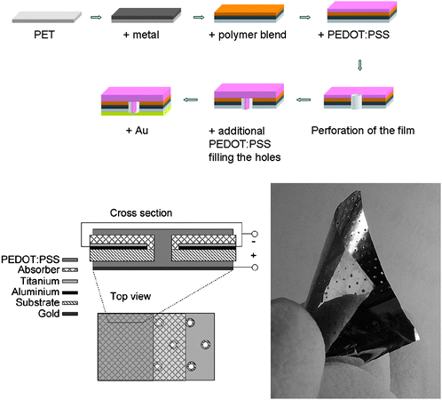 | ||
| Fig. 33 Wrap through cells. Top and lower left: Schematic representation of the inverted layer sequence starting with the metallic contact on the plastic substrate followed by the active polymer blend and PEDOT:PSS. After perforation of the film a second layer of PEDOT:PSS is applied forming the wrap through contact and a gold back electrode is applied to finish the circuitry. Right: Picture of a wrap through device. The two bottom representations are reprinted with permission from ref. 211. © 2007 Elsevier B. V. | ||
The holes/channels through the device are now created by perforation of the device with a hot needle followed by a second layer of PEDOT:PSS forming the wrap through contact. As the last step a metal (Au) back contact was evaporated thermally. Power conversion efficiencies of up to 2% were reached for parallel wrap through and 1.1% was reached for serial circuitry using simulated solar irradiation (1000 W/m2).
Summary and outlook
From a materials point of view, the state-of-the-art in the field of organic photovoltaics has for long been represented by bulk heterojunction solar cells based on P3HT and a fullerene. Power conversion efficiencies in the 4–5% range have been reported for P3HT:PCBM devices,46–50 but reproducibility has been difficult and average efficiencies are significantly lower than the highest reported. P3HT can only absorb light up to 650 nm, and this limited absorption of the available solar photons (up to 22.4%) has in recent years led several research teams to focus on preparation of low band gap polymers in order to be able to exploit a larger part of the solar spectrum. Recently new low band gap polymer:PCBM composites have shown device efficiencies close to and even exceeding that of P3HT:PCBM with plenty of room for improvement.56–58,192Another trail deviating from the traditional P3HT:PCBM blends is the use of two different polymers to act as donor and acceptor in a polymer:polymer heterojunction. Although very little effort has been put into this area moderately good results have been achieved (∼1.8%).69 The advantages of a heterojunction consisting only of absorbing materials, allowing for absorption over a wider spectral range, together with the relative ease of tuning the donor–acceptor energy levels make the polymer:polymer solar cell a potential player in future research. Two major challenges will be the design of good n-type polymers and dealing with the tendency for phase separation of the polymers into larger domains instead of into a fine interpenetrating network that allows for efficient charge separation and transport.
The use of precursor or thermocleavable sidechain routes also results in a higher concentration of the photoactive participant. Heat treatment of the device film results in chemical reactions whereby removal of part of the material (sometimes up to 50% or more by weight) that constitutes the original film is achieved. Thus formed conjugated polymers have no solubilising sidechains and are insoluble in all solvents which induce stability towards degradation and furthermore allows for preparation of multilayer devices by all solution processing.109 Light cleavage using a near-infrared (NIR) dye that is either incorporated in the polymer film or employed as a separate layer on top of the polymer is a sophisticated form of dealing with thermocleavable materials which allows for patterning as thermocleavage only occurs in areas exposed to NIR light.114,115,199 The non-exposed areas which are still soluble can subsequently be removed.
Multilayer devices (tandem cells) allow for use of several types of polymer that each absorb light at different regions of the solar spectrum and hence render the exploitation of the incoming light more effective. The main challenge when preparing all solution processed multilayer devices is to find a way to add a new layer without destroying the underlying layer. Besides the method of rendering the polymer insoluble this can be done by careful tuning of the solvents used for each layer so that the top layer is always insoluble in the solvent used next. PCEs of up to 6.5% have been reported by the latter method.192 An alternative approach to the already mentioned is to use a reflective geometry where the reflected light from one cell is directed towards another and vice versa. This again allows for the use of supplementary polymers that each absorbs light at different wavelengths.
With respect to methods trying to induce stability to the device the use of materials that can be cross-linked after film preparation and consequently a ‘locking’ of the morphology, should be mentioned. Limited research has been carried out within this area that has the potential of solving the problem of phase separation/aggregation that is observed for P3HT:PCBM devices upon thermal treatment. Finding ways to prepare highly cross-linked films would also make the process useful for multilayer devices.
Fabrication of hybrid solar cells is an area that has received quite a lot of attention with respect to device architecture trying to optimize charge separation and collection. Designs where the inorganic part of the heterojunction is represented as nanoparticles, are generated in situ, or as nanorod or -pore structures have been investigated and recently several reports of combining the traditional P3HT:PCBM setup with an inorganic into a 3-component heterojunction has been successful in improving the efficiencies compared with the corresponding P3HT:PCPM devices without the inorganic. Similar tendencies have been reported for heterojunctions of surface modified inorganics with different dyes, where the concentration of the dye is so small that its contribution to absorption is minimal to negligible. Instead the dye aids in charge separation and suppresses back recombination. The latter two examples are good indicators that combining techniques and thinking differently can lead to improvement.
The latest reports are dealing with the fact that indium, which is a major component in the most commonly used transparent electrodes (ITO), is a scarce and expensive element in a world market with a growing demand because of the development within optoelectronics. In order to approach this problem new device designs have been developed to function without ITO. High voltage devices yielding open circuit voltages up to 880 V,210 introduction of the wrap through concept implemented for polymer based solar cells on thin flexible plastic substrates,208 and some of the ITO free polymer solar cell module concepts have even been demonstrated to work in a full roll-to-roll process.200,201 These new concepts still need optimization, but they are approaching relevant issues for industrial manufacturing processes.134,212
It is our opinion that, if the field of polymer solar cells is to advance to a degree where it finally succeeds in leaving the lab to go into actual production and enjoy widespread use, it will be necessary to deviate, in much larger extent than seen so far, from the tendency to just accept the flaws of the ‘main road’ in stead of trying to deal with them. Besides development of new device designs, new materials have to be developed. Tuning of donor–acceptor energy levels in polymer:polymer heterojunctions, in hybrid solar cells or a combination of both, attempts to minimize the amount of non-absorbing or -conducting material from the heterojunction as well as stabilising the same by use of thermocleavable materials are some of the paths where we see a large potential.
There is furthermore a need for more approaches to implement the laboratory small scale fabrication of devices into actual large scale production, in order to gain familiarity with the inevitable problems and challenges that are related to this. This will place demands on the materials properties such that they match relevant processes. This area is relatively new.
Conclusion
Materials, processes and devices that deviate significantly from the standard approach, of rigid glass substrates, indium-tin-oxide electrodes, spincoated layers of conjugated polymer/fullerene mixtures and evaporated metal electrodes in a flat multilayer geometry, that is generally used in the preparation of polymer and organic solar cells, have been presented in this review. Advanced materials such as thermocleavable polymers, for higher level processing and stability, in combination with advanced device concepts like tandem cells and ITO free roll-to-roll coating. All have the potential to go beyond the current state-of-the-art towards real progress in terms of better performance, higher operational stability, facile processing and easier, faster and lower cost production.Acknowledgements
This work was supported by the Danish Strategic Research Council (DSF 2104-05-0052 and 2104-07-0022).References
- T. Ameri, G. Dennler, C. Lungenschmied and C. J. Brabec, Energy Environ. Sci., 2009, 2, 347–363 RSC.
- J. Bouclé, P. Ravirajan and J. Nelson, J. Mater. Chem., 2007, 17, 3141–3153 RSC.
- C. J. Brabec, N. S. Sariciftci and J. C. Hummelen, Adv. Funct. Mater., 2001, 11, 15–26 CrossRef CAS.
- C. J. Brabec, J. A. Hauch, P. Schilinsky and C. Waldauf, MRS Bull., 2005, 30, 50–52.
- C. J. Brabec and J. R. Durrant, MRS Bull., 2008, 33, 670–675 CAS.
- E. Bundgaard and F. C. Krebs, Sol. Energy Mater. Sol. Cells, 2007, 91, 954–985 CrossRef CAS.
- L. M. Chen, Z. R. Hong, G. Li and Y. Yang, Adv. Mater., 2009, 21, 1434–1449 CrossRef CAS.
- K. M. Coakley and M. D. McGehee, Chem. Mater., 2004, 16, 4533–4542 CrossRef CAS.
- K. M. Coakley, Y. X. Liu, C. Goh and M. D. McGehee, MRS Bull., 2005, 30, 37–40 CAS.
- G. Dennler, M. C. Scharber and C. J. Brabec, Adv. Mater., 2009, 21, 1323–1338 CrossRef CAS.
- S. Günes, H. Neugebauer and N. S. Sariciftci, Chem. Rev., 2007, 107, 1324–1338 CrossRef.
- S. Günes and N. S. Sariciftci, Inorg. Chim. Acta, 2008, 361, 581–588 CrossRef.
- A. Hadipour, B. De Boer and P. W. M. Blom, Org. Electron., 2008, 9, 617–624 CrossRef.
- A. Hadipour, B. De Boer and P. W. M. Blom, Adv. Funct. Mater., 2008, 18, 169–181 CrossRef CAS.
- H. Hoppe and N. S. Sariciftci, J. Mater. Res., 2004, 19, 1924–1945 CAS.
- R. A. J. Janssen, J. C. Hummelen and N. S. Saricifti, MRS Bull., 2005, 30, 33–36 CAS.
- M. Jørgensen, K. Norrman and F. C. Krebs, Sol. Energy Mater. Sol. Cells, 2008, 92, 686–714 CrossRef.
- B. Kippelen and J. L. Bredas, Energy Environ. Sci., 2009, 2, 251–261 RSC.
- F. C. Krebs, Refocus, 2005, 6, 38–39 CrossRef.
- R. Kroon, M. Lenes, J. C. Hummelen, P. W. M. Blom and B. De Boer, Polym. Rev., 2008, 48, 531–582 Search PubMed.
- M. T. Lloyd, J. E. Anthony and G. G. Malliaras, Mater. Today, 2007, 10, 34–41 CrossRef CAS.
- A. C. Mayer, S. R. Scully, B. E. Hardin, M. W. Rowell and M. D. McGehee, Mater. Today, 2007, 10, 28–33 CrossRef CAS.
- B. P. Rand, J. Genoe, P. Heremans and J. Poortmans, Progr. Photovolt.: Res. Appl., 2007, 15, 659–676 Search PubMed.
- H. Spanggaard and F. C. Krebs, Sol. Energy Mater. Sol. Cells, 2004, 83, 125–146 CrossRef CAS.
- B. C. Thompson and J. M. J. Frechet, Angew. Chem., Int. Ed., 2008, 47, 58–77 CrossRef.
- C. Winder and N. S. Sariciftci, J. Mater. Chem., 2004, 14, 1077–1086 RSC.
- J. Wood (Ed.), Mater.Today, 2007, 10, pp. 1–50 Search PubMed.
- S. E. Shaheen, D. S. Ginley, and G. E. Jabbour (Guest Eds.), MRS Bull., 2005, 30, pp. 10–52 Search PubMed.
- J. Poortmans (Guest Ed.), Prog.Photovolt., 2007, 15, pp. 657–754 Search PubMed.
- F. C. Krebs (Guest Ed.), Sol. Energy Mater., 2004, 83, pp. 125–321 Search PubMed.
- F. C. Krebs (Guest Ed.), Sol. Energy Mater., 2007, 91, pp. 953–1036 Search PubMed.
- F. C. Krebs (Guest Ed.), Sol. Energy Mater., 2008, 92, pp. 685–820 Search PubMed.
- F. C. Krebs (Guest Ed.), Sol. Energy Mater., 2009, 93, pp. 393–538 Search PubMed.
- Organic Photovoltaics: Concepts and Realization, ed. Brabec, C. J., Dyakonov, V., and Parisi, J., Springer, New York, 2003 Search PubMed.
- Organic Photovoltaics: Mechanisms, Materials and Devices, ed. Sun, S. S. and Sariciftci, N. S., CRC Press, Taylor & Francis Group, Florida, USA, 2005 Search PubMed.
- Nanostructured Materials for Solar Energy Conversion, ed. Soga, T., Elsevier, UK, 2006 Search PubMed.
- Polymer Photovoltaics: A Practical Approach, ed. Krebs, F. C., SPIE Press, Bellingham, 2008 Search PubMed.
- Organic Photovoltaics: Materials, Device Physics and Manufacturing Technologies, ed. Brabec, C. J., Scherf, U., and Dyakonov, V., Wiley-VCH, Weinheim, 2008 Search PubMed.
- N. S. Sariciftci, L. Smilowitz, A. J. Heeger and F. Wudl, Science, 1992, 258, 1474–1476 CrossRef CAS.
- G. Yu, J. Gao, J. C. Hummelen, F. Wudl and A. J. Heeger, Science, 1995, 270, 1789–1791 CrossRef CAS.
- Shawn R. Scully and Michael D. McGehee, J. Appl. Phys., 2006, 100, 034907 CrossRef.
- D. E. Markov, J. C. Hummelen, P. W. M. Blom and A. B. Sieval, Phys. Rev. B: Condens. Matter Mater. Phys., 2005, 72, 045216 CrossRef.
- P. Peumans, A. Yakimov and S. R. Forrest, J. Appl. Phys., 2003, 93, 3693–3723 CrossRef CAS.
- O. Douheret, A. Swinnen, S. Bertho, I. Haeldermans, J. D'Haen, M. D'Olieslaeger, D. Vanderzande and J. V. Manca, Progr. Photovolt.: Res. Appl., 2007, 15, 713–726 Search PubMed.
- B. V. Andersson, A. Herland, S. Masich and O. Inganas, Nano Lett., 2009, 9, 853–855 CrossRef CAS.
- C. J. Ko, Y. K. Lin, F. C. Chen and C. W. Chu, Appl. Phys. Lett., 2007, 90, 063509 CrossRef.
- G. Li, V. Shrotriya, J. S. Huang, Y. Yao, T. Moriarty, K. Emery and Y. Yang, Nat. Mater., 2005, 4, 864–868 CAS.
- W. L. Ma, C. Y. Yang, X. Gong, K. Lee and A. J. Heeger, Adv. Funct. Mater., 2005, 15, 1617–1622 CrossRef CAS.
- M. Reyes-Reyes, K. Kim and D. L. Carroll, Appl. Phys. Lett., 2005, 87, 083506–3 CrossRef.
- M. Reyes-Reyes, K. Kim, J. Dewald, R. Lopez-Sandoval, A. Avadhanula, S. Curran and D. L. Carroll, Org. Lett., 2005, 7, 5749–5752 CrossRef CAS.
- G. Dennler, Mater. Today, 2007, 10, 56 CrossRef.
- J. Gilot, M. M. Wienk and R. A. J. Janssen, Nat. Mater., 2007, 6, 704 CrossRef CAS.
- M. K. Riede, T. Mueller, B. Maennig, K. Leo, K. O. Sylvester-Hvid, B. Zimmermann, M. Niggemann and A. Gombert, Appl. Phys. Lett., 2008, 92, 076101 CrossRef.
- G. P. Smestad, F. C. Krebs, C. M. Lampert, C. G. Granqvist, K. L. Chopra, X. Mathew and H. Takakura, Sol. Energy Mater. Sol. Cells, 2008, 92, 371–373 CrossRef.
- H. A. M. van Mullekom, J. A. J. M. Vekemans, E. E. Havinga and E. W. Meijer, Mater. Sci. Eng., R, 2001, 32, 1–40 CrossRef.
- J. H. Hou, H. Y. Chen, S. Q. Zhang, G. Li and Y. Yang, J. Am. Chem. Soc., 2008, 130, 16144 CrossRef CAS.
- Y. Y. Liang, D. Q. Feng, Y. Wu, S. T. Tsai, G. Li, C. Ray and L. P. Yu, J. Am. Chem. Soc., 2009, 131, 7792–7799 CrossRef CAS.
- J. Peet, J. Y. Kim, N. E. Coates, W. L. Ma, D. Moses, A. J. Heeger and G. C. Bazan, Nat. Mater., 2007, 6, 497–500 CrossRef CAS.
- Z. Zhu, D. Waller, R. Gaudiana, M. Morana, D. Muhlbacher, M. Scharber and C. Brabec, Macromolecules, 2007, 40, 1981–1986 CrossRef CAS.
- S. R. Forrest, MRS Bull., 2005, 30, 28–32 CAS.
- L. J. A. Koster, V. D. Mihailetchi and P. W. M. Blom, Appl. Phys. Lett., 2006, 88, 093511 CrossRef.
- M. C. Scharber, D. Wuhlbacher, M. Koppe, P. Denk, C. Waldauf, A. J. Heeger and C. L. Brabec, Adv. Mater., 2006, 18, 789 CrossRef CAS.
- S. H. Park, A. Roy, S. Beaupre, S. Cho, N. Coates, J. S. Moon, D. Moses, M. Leclerc, K. Lee and A. J. Heeger, Nat. Photonics, 2009, 3, 297–302 Search PubMed.
- N. Blouin, A. Michaud, D. Gendron, S. Wakim, E. Blair, R. Neagu-Plesu, M. Belletete, G. Durocher, Y. Tao and M. Leclerc, J. Am. Chem. Soc., 2008, 130, 732–742 CrossRef CAS.
- J. H. Hou, M. H. Park, S. Q. Zhang, Y. Yao, L. M. Chen, J. H. Li and Y. Yang, Macromolecules, 2008, 41, 6012–6018 CrossRef CAS.
- F. B. Kooistra, J. Knol, F. Kastenberg, L. M. Popescu, W. J. H. Verhees, J. M. Kroon and J. C. Hummelen, Org. Lett., 2007, 9, 551–554 CrossRef CAS.
- J. J. M. Halls, C. A. Walsh, N. C. Greenham, E. A. Marseglia, R. H. Friend, S. C. Moratti and A. B. Holmes, Nature, 1995, 376, 498–500 CrossRef CAS.
- G. Yu and A. J. Heeger, J. Appl. Phys., 1995, 78, 4510–4515 CrossRef CAS.
- C. R. McNeill, A. Abrusci, J. Zaumseil, R. Wilson, M. J. McKiernan, J. H. Burroughes, J. J. M. Halls, N. C. Greenham and R. H. Friend, Appl. Phys. Lett., 2007, 90, 193506 CrossRef.
- M. M. Wienk, J. M. Kroon, W. J. H. Verhees, J. Knol, J. C. Hummelen, P. A. van Hal and R. A. J. Janssen, Angew. Chem., Int. Ed., 2003, 42, 3371–3375 CrossRef CAS.
- M. Granstrom, K. Petritsch, A. C. Arias, A. Lux, M. R. Andersson and R. H. Friend, Nature, 1998, 395, 257–260 CrossRef CAS.
- T. Kietzke, H. H. Horhold and D. Neher, Chem. Mater., 2005, 17, 6532–6537 CrossRef CAS.
- M. M. Koetse, J. Sweelssen, K. T. Hoekerd, H. F. M. Schoo, S. C. Veenstra, J. M. Kroon, X. N. Yang and J. Loos, Appl. Phys. Lett., 2006, 88, 083504 CrossRef.
- R. A. Wessling, J.Pol.Sci.- Pol.Symp., 1985, 55–66 Search PubMed.
- D. R. Gagnon, J. D. Capistran, F. E. Karasz, R. W. Lenz and S. Antoun, Polymer, 1987, 28, 567–573 CrossRef CAS.
- R. W. Lenz, C. C. Han, J. Stengersmith and F. E. Karasz, J. Polym. Sci., Part A: Polym. Chem., 1988, 26, 3241–3249 CrossRef CAS.
- R. O. Garay, B. Mayer, F. E. Karasz and R. W. Lenz, J. Polym. Sci., Part A: Polym. Chem., 1995, 33, 525–531 CAS.
- W. J. Feast and J. N. Winter, J. Chem. Soc., Chem. Commun., 1985, 202–203 RSC.
- D. C. Bott, C. S. Brown, C. K. Chai, N. S. Walker, W. J. Feast, P. J. S. Foot, P. D. Calvert, N. C. Billingham and R. H. Friend, Synth. Met., 1986, 14, 245–269 CrossRef CAS.
- A. Furlani, C. Napoletano, M. V. Russo and W. J. Feast, Polym. Bull., 1986, 16 Search PubMed.
- H. G. Gilch and W. L. Wheelwri, J. Polym. Sci., Part A-1, 1966, 4, 1337–1347 CrossRef CAS.
- H. Spreitzer, H. Becker, E. Kluge, W. Kreuder, H. Schenk, R. Demandt and H. Schoo, Adv. Mater., 1998, 10, 1340–1343 CrossRef CAS.
- F. Louwet, D. Vanderzande, J. Gelan and J. Mullens, Macromolecules, 1995, 28, 1330–1331 CrossRef CAS.
- F. Louwet, D. Vanderzande and J. Gelan, Synth. Met., 1995, 69, 509–510 CrossRef CAS.
- F. Louwet, D. Vanderzande and J. Gelan, Synth. Met., 1992, 52, 125–130 CrossRef CAS.
- T. A. Chen and R. D. Rieke, J. Am. Chem. Soc., 1992, 114, 10087–10088 CrossRef CAS.
- T. A. Chen, X. M. Wu and R. D. Rieke, J. Am. Chem. Soc., 1995, 117, 233–244 CrossRef CAS.
- R. D. McCullough, R. D. Lowe, M. Jayaraman and D. L. Anderson, J. Org. Chem., 1993, 58, 904–912 CrossRef CAS.
- F. C. Krebs, R. B. Nyberg and M. Jørgensen, Chem. Mater., 2004, 16, 1313–1318 CrossRef CAS.
- K. T. Nielsen, K. Bechgaard and F. C. Krebs, Macromolecules, 2005, 38, 658–659 CrossRef CAS.
- K. T. Nielsen, K. Bechgaard and F. C. Krebs, Synthesis, 2006, 1639–1644 CrossRef CAS.
- K. T. Nielsen, P. Harris, K. Bechgaard and F. C. Krebs, Acta Crystallogr., 2007, B-63, 151–156.
- F. C. Krebs and H. Spanggaard, Chem. Mater., 2005, 17, 5235–5237 CrossRef CAS.
- F. C. Krebs and K. Norrman, Progr. Photovolt.: Res. Appl., 2007, 15, 697–712 Search PubMed.
- K. Norrman, J. Alstrup, M. Jørgensen, M. Lira-Cantu, N. B. Larsen and F. C. Krebs, Organic Photovoltaics VII, 2006, 6334, U100–U111 Search PubMed.
- K. Norrman and F. C. Krebs, Sol. Energy Mater., 23-1-2006, 90, 213–227 Search PubMed.
- M. Bjerring, J. S. Nielsen, A. Siu, N. C. Nielsen and F. C. Krebs, Sol. Energy Mater. Sol. Cells, 2008, 92, 772–784 CrossRef CAS.
- M. Bjerring, J. S. Nielsen, N. C. Nielsen and F. C. Krebs, Macromolecules, 2007, 40, 6012–6013 CrossRef CAS.
- S. A. Gevorgyan and F. C. Krebs, Chem. Mater., 2008, 20, 4386–4390 CrossRef CAS.
- J. S. Liu, E. N. Kadnikova, Y. X. Liu, M. D. McGehee and J. M. J. Frechet, J. Am. Chem. Soc., 2004, 126, 9486–9487 CrossRef CAS.
- F. Banishoeib, P. Adriaensens, S. Berson, S. Guillerez, O. Douheret, J. Manca, S. Fourier, T. J. Cleij, L. Lutsen and D. Vanderzande, Sol. Energy Mater. Sol. Cells, 2007, 91, 1026–1034 CrossRef CAS.
- F. Banishoeib, A. Henckens, S. Fourier, G. Vanhooyland, M. Breselge, J. Manca, T. J. Cleij, L. Lutsen, D. Vanderzande, L. H. Nguyen, H. Neugebauer and N. S. Sariciftci, Thin Solid Films, 2008, 516, 3978–3988 CrossRef CAS.
- C. Girotto, D. Cheyns, T. Aernouts, F. Banishoeib, L. Lutsen, T. J. Cleij, D. Vanderzande, J. Genoe, J. Poortman and P. Heremans, Org. Electron., 2008, 9, 740–746 CrossRef CAS.
- A. Henckens, K. Colladet, S. Fourier, T. J. Cleij, L. Lutsen, J. Gelan and D. Vanderzande, Macromolecules, 2005, 38, 19–26 CrossRef CAS.
- L. H. Nguyen, S. Gunes, H. Neugebauer, N. S. Sariciftci, F. Banishoeib, A. Henckens, T. Cleij, L. Lutsen and D. Vanderzande, Sol. Energy Mater. Sol. Cells, 2006, 90, 2815–2828 CrossRef CAS.
- F. Padinger, T. Fromherz, P. Denk, C. J. Brabec, J. Zettner, T. Hierl and N. S. Sariciftci, Synth. Met., 2001, 121, 1605–1606 CrossRef CAS.
- R. D. Scurlock, B. J. Wang, P. R. Ogilby, J. R. Sheats and R. L. Clough, J. Am. Chem. Soc., 1995, 117, 10194–10202 CrossRef CAS.
- M. H. Petersen, S. A. Gevorgyan and F. C. Krebs, Macromolecules, 2008, 41, 8986–8994 CrossRef CAS.
- O. Hagemann, M. Bjerring, N. C. Nielsen and F. C. Krebs, Sol. Energy Mater. Sol. Cells, 2008, 92, 1327–1335 CrossRef CAS.
- C. Edder, P. B. Armstrong, K. B. Prado and J. M. J. Frechet, Chem. Commun., 2006, 1965–1967 RSC.
- G. A. Power, P. Hodge and N. B. McKeown, Chem. Commun., 1996, 655–656 RSC.
- J. H. Edwards, W. J. Feast and D. C. Bott, Polymer, 1984, 25, 395–398 CrossRef CAS.
- J. F. Yu and S. Holdcroft, Macromolecules, 2000, 33, 5073–5079 CrossRef CAS.
- X. Han, X. W. Chen and S. Holdcroft, Adv. Mater., 2007, 19, 1697–1702 CrossRef CAS.
- T. J. Gordon, G. Vamvounis and S. Holdcroft, Adv. Mater., 2008, 20, 2486–2490 CrossRef CAS.
- J. H. Burroughes, D. D. C. Bradley, A. R. Brown, R. N. Marks, K. Mackay, R. H. Friend, P. L. Burns and A. B. Holmes, Nature, 1990, 347, 539–541 CrossRef CAS.
- S. Bertho, I. Haeldermans, A. Swinnen, W. Moons, T. Martens, L. Lutsen, D. Vanderzande, J. Manca, A. Senes and A. Bonfiglio, Sol. Energy Mater. Sol. Cells, 2007, 91, 385–389 CrossRef CAS.
- S. Bertho, G. Janssen, T. J. Cleij, B. Conings, W. Moons, A. Gadisa, J. D'Haen, E. Goovaerts, L. Lutsen, J. Manca and D. Vanderzande, Sol. Energy Mater. Sol. Cells, 2008, 92, 753–760 CrossRef CAS.
- K. Sivula, C. K. Luscombe, B. C. Thompson and J. M. J. Frechet, J. Am. Chem. Soc., 2006, 128, 13988–13989 CrossRef CAS.
- K. Sivula, Z. T. Ball, N. Watanabe and J. M. J. Frechet, Adv. Mater., 2006, 18, 206 CrossRef CAS.
- C. H. Woo, B. C. Thompson, B. J. Kim, M. F. Toney and M. J. Frechet, J. Am. Chem. Soc., 2008, 130, 16324–16329 CrossRef CAS.
- M. Drees, H. Hoppe, C. Winder, H. Neugebauer, N. S. Sariciftci, W. Schwinger, F. Schaffler, C. Topf, M. C. Scharber, Z. G. Zhu and R. Gaudiana, J. Mater. Chem., 2005, 15, 5158–5163 RSC.
- Z. Zhu, S. Hadjikyriacou, D. Waller and R. Gaudiana, J. Macromol. Sci., Part A: Pure Appl. Chem., 2004, 41, 1467–1487 Search PubMed.
- S. Miyanishi, K. Tajima and K. Hashimoto, Macromolecules, 2009, 42, 1610–1618 CrossRef CAS.
- L. D. Bozano, K. R. Carter, V. Y. Lee, R. D. Miller, R. DiPietro and J. C. Scott, J. Appl. Phys., 2003, 94, 3061–3068 CrossRef CAS.
- Y. N. Li, J. F. Ding, M. Day, Y. Tao, J. P. Lu and M. D'iorio, Chem. Mater., 2003, 15, 4936–4943 CrossRef CAS.
- C. D. Müller, A. Falcou, N. Reckefuss, M. Rojahn, V. Wiederhirn, P. Rudati, H. Frohne, O. Nuyken, H. Becker and K. Meerholz, Nature, 2003, 421, 829–833 CrossRef.
- G. L. Wu, C. H. Yang, B. H. Fan, B. Zhang, X. M. Chen and Y. F. Li, J. Appl. Polym. Sci., 2006, 100, 2336–2342 CrossRef CAS.
- H. Yan, P. Lee, N. R. Armstrong, A. Graham, G. A. Evmenenko, P. Dutta and T. J. Marks, J. Am. Chem. Soc., 2005, 127, 3172–3183 CrossRef CAS.
- H. Yan, M. H. Yoon, A. Facchetti and T. J. Marks, Appl. Phys. Lett., 2005, 87, 183501–1 CrossRef.
- C. H. Yang, J. H. Hou, B. Zhang, S. Q. Zhang, C. He, H. Fang, Y. Q. Ding, J. P. Ye and Y. F. Li, Macromol. Chem. Phys., 2005, 206, 1311–1318 CrossRef CAS.
- M. Jørgensen, O. Hagemann, J. Alstrup and F. C. Krebs, Sol. Energy Mater. Sol. Cells, 2009, 93, 413–421 CrossRef CAS.
- F. C. Krebs and M. Jørgensen., WO, 2007118850, 2007.
- F. C. Krebs, M. Jørgensen, K. Norrman, O. Hagemann, J. Alstrup, T. D. Nielsen, J. Fyenbo, K. Larsen and J. Kristensen, Sol. Energy Mater. Sol. Cells, 2009, 93, 422–441 CrossRef CAS.
- F. C. Krebs, Sol. Energy Mater. Sol. Cells, 2009, 93, 465–475 CrossRef CAS.
- E. Itoh, Y. Takamizawa and K. Miyairi, Jpn. J. Appl. Phys., 2008, 47, 509–512 CrossRef CAS.
- S. S. Kim, J. Jo, C. Chun, J. C. Hong and D. Y. Kim, J. Photochem. Photobiol., A, 2007, 188, 364–370 CrossRef CAS.
- N. Kudo, S. Honda, Y. Shimazaki, H. Ohkita, S. Ito and H. Benten, Appl. Phys. Lett., 2007, 90, 183513 CrossRef.
- C. Y. Kuo, W. C. Tang, C. Gau, T. F. Guo and D. Z. Jeng, Appl. Phys. Lett., 2008, 93, 033307 CrossRef.
- Y. Y. Lin, T. H. Chu, C. W. Chen and W. F. Su, Appl. Phys. Lett., 2008, 92, 053312 CrossRef.
- Y. Y. Lin, T. H. Chu, S. S. Li, C. H. Chuang, C. H. Chang, W. F. Su, C. P. Chang, M. W. Chu and C. W. Chen, J. Am. Chem. Soc., 2009, 131, 3644–3649 CrossRef CAS.
- M. C. Wu, C. H. Chang, H. H. Lo, Y. S. Lin, Y. Y. Lin, W. C. Yen, W. F. Su, Y. F. Chen and C. W. Chen, J. Mater. Chem., 2008, 18, 4097–4102 RSC.
- Ming-Chung Wu, Hsueh-Chung Liao, Hsi-Hsing Lo, Sharon Chen, Yun-Yue Lin, Wei-Che Yen, Tsung-Wei Zeng, Chun-Wei Chen, Yang-Fang Chen and Wei-Fang Su, Sol. Energy Mater. Sol. Cells, 2009, 93, 961–965 CrossRef CAS.
- Tsung-Wei Zeng, Hsi-Hsing Lo, Chia-Hao Chang, Yun-Yue Lin, Chun-Wei Chen and Wei-Fang Su, Sol. Energy Mater. Sol. Cells, 2009, 93, 952–957 CrossRef CAS.
- R. Zhu, C. Y. Jiang, X. Z. Liu, B. Liu, A. Kumar and S. Ramakrishna, Appl. Phys. Lett., 2008, 93, 013102 CrossRef.
- W. J. E. Beek, M. M. Wienk and R. A. J. Janssen, Adv. Mater., 2004, 16, 1009–1013 CrossRef CAS.
- W. J. E. Beek, L. H. Slooff, M. M. Wienk, J. M. Kroon and R. A. J. Janssen, Adv. Funct. Mater., 2005, 15, 1703–1707 CrossRef CAS.
- Y. Y. Lin, C. W. Chen, T. H. Chu, W. F. Su, C. C. Lin, C. H. Ku, J. J. Wu and C. H. Chen, J. Mater. Chem., 2007, 17, 4571–4576 RSC.
- Y. Y. Lin, Y. Y. Lee, L. W. Chang, J. J. Wu and C. W. Chen, Appl. Phys. Lett., 2009, 94, 063308 CrossRef.
- D. J. D. Moet, L. J. A. Koster, B. De Boer and P. W. M. Blom, Chem. Mater., 2007, 19, 5856–5861 CrossRef CAS.
- D. C. Olson, J. Piris, R. T. Collins, S. E. Shaheen and D. S. Ginley, Thin Solid Films, 2006, 496, 26–29 CrossRef CAS.
- D. C. Olson, S. E. Shaheen, R. T. Collins and D. S. Ginley, J. Phys. Chem. C, 2007, 111, 16670–16678 CrossRef CAS.
- K. Takanezawa, K. Hirota, Q. S. Wei, K. Tajima and K. Hashimoto, J. Phys. Chem. C, 2007, 111, 7218–7223 CrossRef CAS.
- K. Takanezawa, K. Tajima and K. Hashimoto, Appl. Phys. Lett., 2008, 93, 063308 CrossRef.
- R. Thitima, C. Patcharee, S. Takashi and Y. Susumu, Solid-State Electron., 2009, 53, 176–180 CrossRef CAS.
- H. M. P. Wong, P. Wang, A. Abrusci, M. Svensson, M. R. Andersson and N. C. Greenham, J. Phys. Chem. C, 2007, 111, 5244–5249 CrossRef CAS.
- F. C. Krebs, Sol. Energy Mater. Sol. Cells, 2008, 92, 715–726 CrossRef CAS.
- F. C. Krebs, Y. Thomann, R. Thomann and J. W. Andreasen, Nanotechnology, 2008, 19, 424013 CrossRef.
- I. Gur, N. A. Fromer, C. P. Chen, A. G. Kanaras and A. P. Alivisatos, Nano Lett., 2007, 7, 409–414 CrossRef CAS.
- W. U. Huynh, J. J. Dittmer and A. P. Alivisatos, Science, 2002, 295, 2425–2427 CrossRef CAS.
- B. Q. Sun, E. Marx and N. C. Greenham, Nano Lett., 2003, 3, 961–963 CrossRef CAS.
- B. Q. Sun, H. J. Snaith, A. S. Dhoot, S. Westenhoff and N. C. Greenham, J. Appl. Phys., 2005, 97, 014914 CrossRef.
- B. Q. Sun and N. C. Greenham, Phys. Chem. Chem. Phys., 2006, 8, 3557–3560 RSC.
- P. Wang, A. Abrusci, H. M. P. Wong, M. Svensson, M. R. Andersson and N. C. Greenham, Nano Lett., 2006, 6, 1789–1793 CrossRef CAS.
- W. Lee, S. Shin, S. H. Han and B. W. Cho, Appl. Phys. Lett., 2008, 92, 193307 CrossRef.
- L. Wang, Y. S. Liu, X. Jiang, D. H. Qin and Y. Cao, J. Phys. Chem. C, 2007, 111, 9538–9542 CrossRef CAS.
- A. A. R. Watt, D. Blake, J. H. Warner, E. A. Thomsen, E. L. Tavenner, H. Rubinsztein-Dunlop and P. Meredith, J. Phys. D: Appl. Phys., 2005, 38, 2006–2012 CrossRef CAS.
- D. H. Cui, J. Xu, T. Zhu, G. Paradee, S. Ashok and M. Gerhold, Appl. Phys. Lett., 2006, 88, 183111 CrossRef.
- N. Kudo, Y. Shimazaki, H. Ohkita, M. Ohoka and S. Ito, Sol. Energy Mater. Sol. Cells, 2007, 91, 1243–1247 CrossRef CAS.
- J. S. Huang, C. Y. Hsiao, S. J. Syu, J. J. Chao and C. F. Lin, Sol. Energy Mater. Sol. Cells, 2009, 93, 621–624 CrossRef CAS.
- C. Y. Liu, Z. C. Holman and U. R. Kortshagen, Nano Lett., 2009, 9, 449–452 CrossRef CAS.
- N. C. Greenham, X. G. Peng and A. P. Alivisatos, Phys. Rev. B: Condens. Matter Mater. Phys., 1996, 54, 17628–17637 CrossRef CAS.
- B. R. Saunders and M. L. Turner, Adv. Colloid Interface Sci., 2008, 138, 1–23 CrossRef CAS.
- P. A. van Hal, M. M. Wienk, J. M. Kroon, W. J. H. Verhees, L. H. Slooff, W. J. H. van Gennip, P. Jonkheijm and R. A. J. Janssen, Adv. Mater., 2003, 15, 118 CrossRef CAS.
- L. H. Slooff, M. M. Wienk and J. M. Kroon, Thin Solid Films, 2004, 451–452, 634–638 CrossRef CAS.
- M. Okuya, K. Nakade and S. Kaneko, Sol. Energy Mater. Sol. Cells, 2002, 70, 425–435 CrossRef CAS.
- K. M. Coakley and M. D. McGehee, Appl. Phys. Lett., 2003, 83, 3380–3382 CrossRef CAS.
- C. Goh, K. M. Coakley and M. D. McGehee, Nano Lett., 2005, 5, 1545–1549 CrossRef CAS.
- V. Gowrishankar, N. Miller, M. D. McGehee, M. J. Misner, D. Y. Ryu, T. P. Russell, E. Drockenmuller and C. J. Hawker, Thin Solid Films, 2006, 513, 289–294 CrossRef CAS.
- G. K. Mor, O. K. Varghese, M. Paulose, K. Shankar and C. A. Grimes, Sol. Energy Mater. Sol. Cells, 2006, 90, 2011–2075 CrossRef CAS.
- P. Ravirajan, A. M. Peiro, M. K. Nazeeruddin, M. Graetzel, D. D. C. Bradley, J. R. Durrant and J. Nelson, J. Phys. Chem. B, 2006, 110, 7635–7639 CrossRef CAS.
- D. Cheyns, H. Gommans, M. Odijk, J. Poortmans and P. Heremans, Sol. Energy Mater. Sol. Cells, 2007, 91, 399–404 CrossRef CAS.
- B. P. Rand, P. Peumans and S. R. Forrest, J. Appl. Phys., 2004, 96, 7519–7526 CrossRef CAS.
- J. Xue, S. Uchida, B. P. Rand and S. R. Forrest, Appl. Phys. Lett., 2004, 84, 3013–3015 CrossRef CAS.
- J. Xue, S. Uchida, B. P. Rand and S. R. Forrest, Appl. Phys. Lett., 2004, 85, 5757–5759 CrossRef CAS.
- A. Yakimov and S. R. Forrest, Appl. Phys. Lett., 2002, 80, 1667 CrossRef CAS.
- A. Colsmann, J. Junge, C. Kayser and U. Lemmer, Appl. Phys. Lett., 2006, 89, 203506 CrossRef.
- G. Dennler, H. J. Prall, R. Koeppe, M. Egginger, R. Autengruber and N. S. Sariciftci, Appl. Phys. Lett., 2006, 89, 073502 CrossRef.
- A. Hadipour, B. De Boer, J. Wildeman, F. B. Kooistra, J. C. Hummelen, M. G. R. Turbiez, M. M. Wienk, R. A. J. Janssen and P. W. M. Blom, Adv. Funct. Mater., 2006, 16, 1897–1903 CrossRef CAS.
- H. J. Prall, R. Koeppe, R. Autengruber, M. Egginger, D. Dennler, and N. S. Sariciftci, From Evaporation to Solution Processed Organic Tandem Solar Cells, Gombert, Andreas, , Strasbourg, France, 21-4-2006 Search PubMed.
- J. Gilot, M. M. Wienk and R. A. J. Janssen, Appl. Phys. Lett., 2007, 90, 143512–143513 CrossRef.
- J. Y. Kim, K. Lee, N. E. Coates, D. Moses, T. Q. Nguyen, M. Dante and A. J. Heeger, Science, 2007, 317, 222–225 CrossRef CAS.
- J. Y. Kim, S. H. Kim, H. H. Lee, K. Lee, W. L. Ma, X. Gong and A. J. Heeger, Adv. Mater., 2006, 18, 572–576 CrossRef CAS.
- V. Andersson, K. Tvingstedt and O. Inganas, J. Appl. Phys., 2008, 103, 094520 CrossRef.
- S. B. Rim, S. Zhao, S. R. Scully, M. D. McGehee and P. Peumans, Appl. Phys. Lett., 2007, 91, 243501 CrossRef.
- K. Tvingstedt, V. Andersson, F. Zhang and O. Inganas, Appl. Phys. Lett., 2007, 91, 123514–3 CrossRef.
- Y. H. Zhou, F. L. Zhang, K. Tvingstedt, W. J. Tian and O. Inganas, Appl. Phys. Lett., 2008, 93, 033302 CrossRef.
- J. W. Andreasen, M. Jørgensen and F. C. Krebs, Macromolecules, 2007, 40, 7758–7762 CrossRef CAS.
- T. J. Gordon, J. F. Yu, C. Yang and S. Holdcroft, Chem. Mater., 2007, 19, 2155–2161 CrossRef CAS.
- F. C. Krebs, Org. Electron., 2009, 10, 761–768 CrossRef CAS.
- F. C. Krebs, Sol. Energy Mater., 2009, 93, 1636–1641 CrossRef CAS.
- T. Aernouts, P. Vanlaeke, W. Geens, J. Poortmans, P. Heremans, S. Borghs, R. Mertens, R. Andriessen and L. Leenders, Thin Solid Films, 2004, 451–452, 22–25 CrossRef.
- A. Gadisa, K. Tvingstedt, S. Admassie, L. Lindell, X. Crispin, M. R. Andersson, W. R. Salaneck and O. Inganas, Synth. Met., 2006, 156, 1102–1107 CrossRef CAS.
- J. Y. Lee, S. T. Connor, Y. Cui and P. Peumans, Nano Lett., 2008, 8, 689–692 CrossRef CAS.
- M. Strange, D. Plackett, M. Kaasgaard and F. C. Krebs, Sol. Energy Mater. Sol. Cells, 2008, 92, 805–813 CrossRef CAS.
- K. Tvingstedt and O. Inganas, Adv. Mater., 2007, 19, 2893–2897 CrossRef CAS.
- B. Winther-Jensen and F. C. Krebs, Sol. Energy Mater. Sol. Cells, 2006, 90, 123–132 CrossRef CAS.
- B. Zimmermann, M. Glatthaar, M. Niggemann, M. K. Riede, A. Hinsch and A. Gombert, Sol. Energy Mater. Sol. Cells, 2007, 91, 374–378 CrossRef CAS.
- J. M. Gee, W. K Schubert, and P. A. Basore, Photovoltaic Specialists Conference, Conference Record of the Twenty Third IEEE, 1993, 265–270 Search PubMed.
- M. Niggemann, W. Graf and A. Gombert, Adv. Mater., 2008, 20, 4055 CrossRef CAS.
- M. Niggemann, B. Zimmermann, J. Haschke, M. Glatthaar and A. Gombert, Thin Solid Films, 2008, 516, 7181–7187 CrossRef CAS.
- F. C. Krebs, S. A. Gevorgyan and J. Astrup, J. Mater. Chem., 2009, 19, 5442–5451 RSC.
| This journal is © The Royal Society of Chemistry 2010 |