Direct carbon conversion in a SOFC-system with a non-porous anode
S.
Nürnberger
a,
R.
Bußar
a,
P.
Desclaux
a,
B.
Franke
a,
M.
Rzepka
*a and
U.
Stimming
ab
aZAE Bayern, Division 1, Walther-Meißner-Str. 6, 85748, Garching, Germany. E-mail: rzepka@muc.zae-bayern.de; Fax: +49-89-329442-12; Tel: +49 (0)89![[thin space (1/6-em)]](https://www.rsc.org/images/entities/char_2009.gif) 329442
329442![[thin space (1/6-em)]](https://www.rsc.org/images/entities/char_2009.gif) 31
31
bTU München, Department of Physics E19, James-Franck-Str. 1, 85748, Garching, Germany
First published on 9th November 2009
Abstract
The direct carbon fuel cell (DCFC) is a special type of high temperature fuel cell which allows direct conversion of the chemical energy of different carbon materials into electricity. The thermodynamic efficiency of this process is high, and thus the overall conversion efficiency has the potential to exceed these of other fuel cell concepts. Until now the most developed DCFC-systems are based on molten carbonate or hydroxide as electrolyte. In this publication we show that also for a system with a solid electrolyte such as in solid oxide fuel cells (SOFC), which suffers, in principle, from limited contact between the solid fuel and the solid electrolyte, significant conversion rates can be achieved at such interfaces. The principal aspects of the direct electrochemical conversion of carbon powders in an SOFC-system have been investigated in the temperature range of 800 °C to 1000 °C. It has been shown that using a flat planar anode, carbon conversion rates exceeding 100 mA cm−2 are possible. Different solid fuels have been investigated in order to determine the influence of carbon properties on the electrochemical conversion.
1. Introduction
The worldwide growing demand for electrical energy cannot be compensated by renewable energies in the medium term. Thus, new and improved concepts are required in order to use the limited fossil energy carriers in a more efficient way. A promising development in this context could be direct carbon fuel cell systems (DCFC) that use cheap and abundant coal as fuel and additionally benefit from its high thermodynamic conversion efficiency. In a DCFC in contrast to all other gas-fed fuel cell systems the stored chemical energy of a solid fuel is directly converted into electricity. The overall cell reaction (eqn (1)) is based on the complete electrochemical oxidation of carbon to carbon dioxide (CO2) in a four-electron process.| C + O2 → CO2 | (1) |
The thermodynamic efficiency slightly exceeds 100%—almost independent of conversion temperature (Fig. 1). This is due to a positive near-zero entropy change of the cell reaction (ΔS° = 2.9 J K−1 mol−1)1. Furthermore, the anodic exhaust gas of a DCFC consists of almost pure CO2 that can be captured and sequestered with less difficulty than for e.g. conventional thermal power plants. The latter is due to the fact that either the oxy-fuel process needs to be used or additional energy is required in order to separate nitrogen (N2) from the off-gas-stream. Another advantage of a DCFC is that the fuel utilisation can reach up to 100%, since a solid fuel is used. This is due to the fact that the reaction product, CO2, exists in a separate gas phase and thus does not influence activity of the solid carbon.
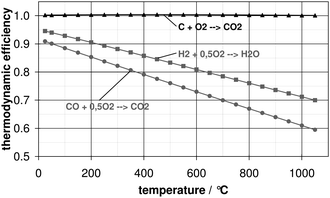 | ||
| Fig. 1 Thermodynamic efficiency as function of temperature for different reactions; triangles: carbon oxidation; squares: hydrogen oxidation; circles: carbon monoxide oxidation. | ||
Recently, three different concepts of a DCFC based on different electrolytes have been discussed: molten carbonate, molten hydroxide or solid ceramic material YSZ (yttria-stabilised zirconia). It should be mentioned that performance data of different concepts, presented in the following, cannot be compared directly, because they strongly depend on e.g. used carbon fuel material, operating temperature and the concept itself (anode/electrolyte material).
The most developed DCFC-systems are those based on molten carbonate electrolyte.1–3 Cooper and coworkers1 from Lawrence Livermore National Laboratory (LLNL) achieved power densities in the range of 40 to 100 mW cm−2 (0.8 V cell voltage, 800 °C) for different carbon materials. They operated a cell for 30 h at a power output of 27 mW cm−2 (∼1 V cell voltage, 800 °C). Nevertheless, carbonate-based cells suffer from corrosion problems which limits the choice of materials.1,4–6
Zecevic et al.7 at Scientific Applications and Research Associates (SARA) developed a DCFC using a molten hydroxide electrolyte. Peak power densities up to 120–180 mW cm−2 were observed and an average power output of 40 mW cm−2 (0.3 V cell voltage, 630 °C) was achieved over 540 h. The most important problems with hydroxide cells are (i) corrosion of materials and (ii) degradation of the electrolyte due to formation of carbonates during carbon electrooxidation.4,5,7
Another concept of a DCFC is based on the combination of solid oxide fuel cell (SOFC) and molten carbonate fuel cell (MCFC) technology. Balachov and coworkers at SRI International demonstrated peak power densities of 10 to 110 mW cm−2 (0.7 V cell voltage) in a temperature range of 700 to 950 °C, using different carbon containing materials e.g. plastic.4 Irvine and coworkers5,8,9 kept a cell running over ten hours at a power output of 10 mW cm−2 (0.5 V cell voltage, 700 °C).
Duskin and Gür at Direct Carbon Technologies (DCT) operate a DCFC combining SOFC and fluidized-bed technologies.10,11 This concept is based on the gasification of carbon to carbon monoxide (CO). The CO is in situ formed via Boudouard reaction (CO2 + C → 2CO) and then electrochemically oxidized to CO2 (CO + 0.5O2 → CO2) in a two electron process. For this cell reaction the thermodynamic efficiency is smaller as compared to thermodynamic efficiency of the direct carbon electrooxidation (Fig. 1). Peak power densities up to 140 mW cm−2 (0.5 V cell voltage, 900 °C) have been achieved using this concept.10,11
It has been reported6,7 that the direct conversion of a solid fuel on a solid electrolyte (e.g. YSZ) suffers from low performance because of poor point-like contact between two solid materials. Additionally, carbon fuel needs to be in close contact with the anode material and the active area is limited to the geometric surface area. But as particle density in solid carbon is about 4 orders of magnitude higher than particle density of a gaseous fuel, a smaller active contact area can even be overcompensated, although for gaseous fuels a porous electrode shows typically an at least 3 orders of magnitude larger surface area12 compared to the flat electrode.
Solid oxide fuel cells (SOFC) show high fuel flexibility. As oxygen ions are transported through the electrolyte a SOFC can theoretically be operated on any combustible fuel, thus also on carbon. In principle, a DCFC with a solid electrolyte may be advantageous for fundamental investigations because it does not suffer from corrosion or degradation of the electrolyte. Compared to other DCFCs, a SOFC based system is rather simple, as no recycle loops for CO2 or water management solutions are needed. Furthermore, SOFC systems allow implementation of catalytically active materials within modified anodes in order to enhance carbon electrooxidation.
2. Experimental
The direct electrochemical conversion of carbon powders on ceramic solid oxide fuel cells (SOFC) without a porous anode layer has been investigated in the temperature range of 800 °C to 1000 °C. The experimental setup is schematically shown in Fig. 2. The cell housing is made of aluminium oxide and allows the cell to be fuelled either by carbon or H2 and CO for reference measurements. The electrode surface of the planar commercial electrolyte supported cells has a geometric area of 7 cm2. The electrolyte with a thickness of about 100 μm is 3YSZ (3 mol% Y2O3 doped ZrO2) and the cathode consists of YSZ/LSM (lanthanum strontium manganese oxide) with a thickness of 45 μm. The used cells have no special anode layer, the carbon is in direct contact with the flat electrolyte surface.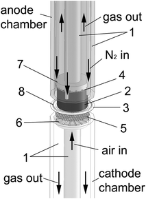 | ||
| Fig. 2 Schematic drawing of the cell. (1) aluminium oxide tubes; (2) carbon pellet; (3) YSZ electrolyte; (4) current collector mesh (Ni); (5) current collector mesh (Pt); (6) cathode flow field; (7) anode flow field; (8) gold wire. | ||
As carbon fuel, pure carbon materials with different particle sizes and different morphologies have been used: (i) amorphous material Vulcan XC72 from Cabot Corporation (particle size 5–10 μm, BET-surface ∼250 m2g−1) and (ii) graphitic material GFG 50M from SGL Carbon (particle size 40–60 μm, BET-surface ∼20 m2g−1). The inserted carbon powders have been formed into porous pellets (3 cm in diameter, 1–2 cm in height) with a porosity of about 85% for Vulcan XC72 and 90% for GFG 50M. Carbon acts as both fuel and current collector at the same time. At room temperature, the specific Ohmic resistance of the used pellets is about 9 × 10⁻⁴ Ω m for GFG 50M and 6 × 10⁻³ Ω m for Vulcan XC72. These values are very high compared to the literature value for graphite of 8 × 10⁻⁶ Ω m. The difference can be explained by porosity and grain boundary resistance inside the pellets. Good contact between the carbon pellet and electrolyte and between current collector mesh (Ni) and carbon was achieved by pressing the current collector against the backside of the pellet with about 4 N cm−2. Nitrogen gas has been flowed (50 to 250 cm3 min−1) during measurements into the anode compartment to blow off the product gas and prevent oxygen getting inside. For all experiments, on the cathode side synthetic air was introduced with a flow rate of 300 cm3 min−1 and 50 cm3 min−1 for the long term run. A gold wire was used to sealing the anode chamber.
For reference measurements with CO on the same cell described above, without special anode layer, the current collector was fixed with Pt paste on the anode side. As fuel, a mixture of 68% CO and 32% CO2 was used. For both the anode and cathode compartment, the flow rate was 300 cm3 min−1.
Electrochemical measurements were made with a potentiostat/galvanostat (Autolab PGSTAT302N) and current–voltage curves were recorded using a NTL 1500M-30 electronic load by F.u.G. Elektronik GmbH. The composition of outlet gases was analyzed by a gas chromatograph (Agilent, MicroGC M200).
3. Results and discussion
The obtained current voltage curves for Vulcan XC72 and GFG 50M on a cell with a non-porous anode at different operating temperatures are shown in Fig. 3. As can be seen, using the amorphous carbon material as fuel at 1000 °C, current densities up to 100 mA cm−2 at a cell voltage of about 0.4 V (i.e. 40 mW cm−2) have been observed. As the product gas of the DCFC is CO2 and the latter is in direct contact with carbon, CO might be formed via the Boudouard reaction (CO2 + C → 2CO), which can, in principle, be oxidized electrochemically in a second step. Therefore, reference measurements with CO as fuel have been made on the same cell (Fig. 4), but without carbon in the system. The observed reaction rates for CO oxidation of 2.5 mA cm−2 at 0.6 V and 1000 °C are negligible on such a surface (no porous anode layer). For comparison, repeating the same experiment with CO as fuel on the same cell, but with porous Ni containing anode layer, at 0.6 V current densities exceeding 280 mA cm−2 could be observed at 1000 °C. Thus, for measurements with carbon as fuel on a cell without a porous anode layer, the electrochemical oxidation of CO can be neglected. Additionally, the obtained current voltage curves for both Vulcan XC72 and GFG 50M (Fig. 3) showed no dependency on the nitrogen flow rate. Thus, a gaseous component such as CO formed in situ via the Boudouard reaction does not contribute to the overall electrochemical reaction. Therefore, carbon can be considered as a direct fuel for these measurements, allowing us to learn something about its reaction kinetics.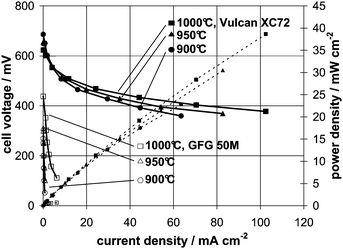 | ||
| Fig. 3 Current voltage curves for Vulcan XC72 (filled symbols) and GFG 50M (open symbols) on a non-porous anode; dashed lines represent power densities. | ||
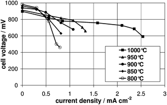 | ||
| Fig. 4 Current voltage curves for CO as fuel on a non-porous anode. Please note that due to very small current densities the x-axis is broadened in scale. | ||
The graphitic carbon material shows considerable lower current densities for identical operation conditions and the observed open circuit voltage is about 0.3 V lower compared to the amorphous material. Arrhenius analysis yields a clearly lower energy of activation for the amorphous carbon fuel (∼100 kJ mol−1 for Vulcan XC72) compared to a crystalline fuel (∼290 kJ mol−1 for GFG 50M). The high reactivity of amorphous carbon can be explained by the poor crystallization and large surface area.4 As the observed activation barriers are of the same order of magnitude as compared to Boudouard reaction (256 kJ mol−1 for graphite and 95–140 kJ mol−1 for amorphous carbon13) it can be concluded that scission of carbon bonds being the most important reaction step within the electrooxidation of carbon.
A long-term run at constant cell voltage of 0.4 V and temperature of 900 °C has been acquired for the amorphous carbon Vulcan XC72 as shown in Fig. 5. Since the voltage drop over the Ohmic resistance of the carbon pellet is always included in the measurement the actual current density is dependent on the thickness of the fuel pellet. The thickness x(t) of the carbon pellet is decreasing in time since the material is consumed both due to electrooxidation and Boudouard reaction:
 | (2) |
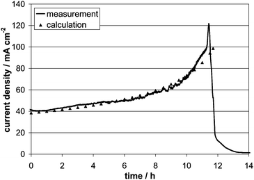 | ||
| Fig. 5 Current transient for long-term operation with Vulcan XC72 at 0.4 V and 900 °C. | ||
According to the thickness, the Ohmic resistance of the pellet decreases with time and consequently the current density increases with time in more than just a linear way until all fuel inside the cell is consumed (the drop of current in Fig. 5). By integration of the current density shown in Fig. 5 the amount of carbon converted into electricity can be calculated. Comparing this value with the total mass of the initial carbon pellet indicates that only 60% of the fuel is oxidized electrochemically, which determines the factor b ≈ 1.6 in eqn (2). The rest of the carbon is very likely converted into CO, via the Boudouard reaction, which has been detected in the exhaust gas stream. The escaping CO results in a fuel utilisation smaller 100% for carbon electrooxidation.
The difference between experimental and calculated data at high current densities in Fig. 5 might be due to a structural change of the pellet. Furthermore, after most of the carbon pellet is consumed nickel (the anode current collector mesh) is present at the three phase boundary, which might accelerate catalytically the electrochemical oxidation of carbon. A good contact between carbon and electrolyte was observed during long-term measurement over 12 h and no residues of the carbon (high purity) remained on the anode side. Principally by using an anode layer with in-plane conductivity, to avoid the voltage drop over carbon pellet, it is possible to obtain about 40 mW cm−2 of constant power output over at least 12 h.
4. Summary and outlook
The principal aspects of the direct electrochemical conversion of carbon powders in a SOFC-system without a porous anode have been investigated in the temperature range of 800 °C to 1000 °C. It has been shown that carbon conversion rates exceeding 100 mA cm−2 at 0.4 V (40 mW cm−2) are possible even in long-term operation over 12 h. Two different solid fuels have been investigated where amorphous carbon material show higher power densities as compared to crystalline graphite material. In order to enhance kinetics of carbon electrooxidation, catalytically active materials will be implemented within anode layers in further investigations.To avoid fuel loss caused by CO formation via the Boudouard-reaction, in general lower operating temperatures (600–700 °C) should be aimed for. This can be achieved by using e.g. modified CGO (gadolinia-doped ceria) as the electrolyte.
References
- N. J. Cherepy, R. Krueger, K. J. Fiet, A. F. Jankowski and J. F. Cooper, Direct conversion of carbon fuels in a molten carbonate fuel cell, J. Electrochem. Soc., 2005, 152(1), A80–A87 CrossRef CAS.
- D. G. Vutetakis, D. R. Skidmore and H. J. Byker, Electrochemical oxidation of molten carbonate–coal slurries, J. Electrochem. Soc., 1987, 134(12), 3027–3035 CrossRef CAS.
- W. H. A. Peelen, M. Olivry, S. F. Au, J. D. Fehribach and K. Hemmes, Electrochemical oxidation of carbon in a 62/38 mol% Li/K carbonate melt, J. Appl. Electrochem., 2000, 30, 1389–1395 CrossRef CAS.
- D. Cao, Y. Sun and G. Wang, Direct carbon fuel cell: Fundamentals and recent developments, J. Power Sources, 2007, 167, 250–257 CrossRef CAS.
- K. Pointon, B. Lakeman, J. Irvine, J. Bradley and S. Jain, The development of a carbon–air semi fuel cell, J. Power Sources, 2006, 162, 750–756 CrossRef CAS.
- A. L. Dicks, The role of carbon in fuel cells, J. Power Sources, 2006, 156, 128–141 CrossRef CAS.
- S. Zecevic, E. M. Patton and P. Parhami, Carbon–air fuel cell without a reforming process, Carbon, 2004, 42, 1983–1993 CrossRef CAS.
- S. L. Jain, Y. Nabae, B. J. Lakeman, K. D. Pointon and J. T. S. Irvine, Solid state electrochemistry of direct carbon/air fuel cells, Solid State Ionics, 2008, 179, 1417–1421 CrossRef CAS.
- S. L. Jain, J. B. Lakeman, K. D. Pointon and J. T. S. Irvine, A novel direct carbon fuel cell concept, J. Fuel Cell Sci. Technol., 2007, 4, 280–282 CrossRef CAS.
- S. Li, A. C. Lee, R. E. Mitchell and T. M. Gür, Direct carbon conversion in a helium fluidized bed fuel cell, Solid State Ionics, 2008, 179, 1549–1552 CrossRef CAS.
- A. C. Lee, S. Li, R. E. Mitchell and T. M. Gür, Conversion of solid carbonaceous fuels in a fluidized bed fuel cell, Electrochem. Solid-State Lett., 2008, 11(2), B20–B23 CrossRef CAS.
- J. Larminie, A. Dicks, Fuel Cell Systems Explained, Wiley-VCH, 2000 (ISBN-10: 0471490261) Search PubMed.
- J. S. J. Van Deventer and P. R. Visser, On the role of the Boudouard reaction in the isothermal reduction of iron ore by char and graphite, Thermochim. Acta, 1987, 111, 89–102 CrossRef CAS.
| This journal is © The Royal Society of Chemistry 2010 |
