Fabrication of biomolecular devices via supramolecular contact-based approaches
Ozge
Akbulut
,
Arum Amy
Yu
and
Francesco
Stellacci
*
Department of Materials Science and Engineering, MIT, Cambridge, MA, USA. E-mail: frstella@mit.edu
First published on 19th October 2009
Abstract
This tutorial review provides an outlook on contact-based fabrication methods suitable for biomolecular platforms. Contact-based methods have emerged in response to serial and expensive fabrication techniques that built devices in a serial way, typically point by point or region by region. The review surveys the biological applications of microcontact printing and affinity contact printing. There is a special focus on DNA printing methods harnessing the supramolecular interactions between two complementary DNA strands.
 Ozge Akbulut | Ozge Akbulut, is a PhD candidate in Prof. Stellacci’s group at MIT in the Department of Materials Science and Engineering. She received her BS in Materials Science and Engineering from Sabanci University, Istanbul, Turkey in 2004. |
 Arum Amy Yu | Arum Amy Yu has received her PhD in Prof. Stellacci’s group at MIT in Materials Science and Engineering in 2007. After her post-doctoral experience in Massachusetts General Hospital and MIT, she joined Samsung, South Korea in 2009. |
 Francesco Stellacci | Francesco Stellacci received his ‘‘Laurea’’ in 1998 at the Politecnico di Milano in Materials Science and Engineering with a thesis on photochromic materials with Prof. Giuseppe Zerbi. He then moved to the University of Arizona for a post-doctoral experience with Prof. J. W. Perry working on the two-photon microfabrication of metallic structures. Since 2002 he is at the Department of Materials Science and Engineering, MIT; he now holds the Paul M. Cook Career Development Associate Professor chair. |
1. Introduction
The diffusion and impact of micro- and nanotechnology fabricated devices will critically depend on their price, which is determined in a sizeable fraction by the cost of the fabrication process. Hence, lowering fabrication costs has been one of the priorities for researchers in fields as disparate as information- and biotechnology. To date, a large fraction of integrated devices is produced through the lithographic generation of a master that then is reproduced multiple times through a stamping approach. Contact-based stamping methods are widely used to physically shape or to chemically modify target substrates in a cost effective way.1 In general, they involve a mold or a stamp that carries the ‘information’ to be transferred onto the target substrate. This ‘information’ may be a specific shape. The embossing of music CDs is a classical example, where a template transfers a physical shape onto millions of CDs. At the nanoscale contact-based stamping is known as imprinting; one example is nanoimprint lithography where a hard mold is pressed onto the appropriate secondary substrate and introduces certain topography. The ‘information’ may also be a chemical pattern. For example, in microcontact printing usually an elastomeric stamp is used to transfer molecules upon contact.1Biomolecular platforms such as DNA microarrays have been proven to be indispensable tools for diagnostics, medical research, toxicology and pharmacology.2 Newer type of assays, protein and antibody microarrays, are also expected to be crucial for determining gene function/regulation and wide-screening of protein function.3 However, the possibility of utilizing these platforms more extensively depends on the development of cost effective fabrication methods. Nowadays, commercial methods to produce DNA microarrays include spotting (by contact, such as pin based fluid transfer, and by non-contact printing, such as piezo based ink-jet printing) and in situ synthesis.2,4 These methods are all serial in nature; hence expensive. Protein and antibody microarrays are in their infancy compared to their DNA counterparts, with whom they share some fabrication approaches such as spotting.5
Contact-based methods are suggested to overcome the cost based issues since they potentially allow parallel fabrication. In this tutorial review, contact-based methods suitable for the fabrication of biomolecular devices or arrays are discussed. All of these methods utilize a stamp (a transfer medium) that is copied onto a target substrate using forces that are suitable to biomolecules. The focus is on ink-based stamping techniques; here ‘ink’ is defined as the molecules to be transferred to the target substrate. The types of stamps and inks, target molecule immobilization methods such as available chemistries as well as the resolution and coverage aspects of each technique are discussed.
2. Microcontact printing
Microcontact printing (μCP) developed by Whitesides’ group is the most popular soft-material contact-based printing technique.6,7 In general, an elastomer stamp, typically made of poly(dimethylsiloxane) (PDMS) is used to obtain conformal contact between the stamp and target substrate, and the transfer of ink molecules occurs at the area of contact. This simple and versatile printing technique is good for printing soft molecules since it doesn’t require either expensive equipment or harsh chemical treatments.After preparation of the stamp, the printing cycle of μCP is composed of three steps: inking – contact – release, as illustrated in Fig. 1. For inking, a solution of ink molecules is dropped onto a stamp (i.e. a substrate with a three dimensionally patterned surface) followed by drying; thus ink molecules are physisorbed on the surface of the stamp. Subsequently, the stamp is placed onto a secondary substrate (contact), so that portions of its surface are in contact with it. The ink molecules in contact with this substrate diffuse onto it. Finally, the stamp is removed from the secondary substrate leaving the desired pattern on it (release).8
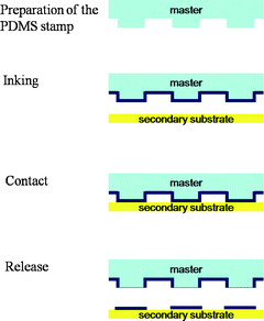 | ||
| Fig. 1 Schematic illustration of the microcontact printing process: preparation of the template, inking of the template, contact with the secondary substrate and releasing the template; the ink is patterned on the secondary substrate. | ||
The elastomeric stamp used in μCP is prepared by casting a polymer (or a pre-polymer), mostly PDMS pre-polymer, onto a mold. The mold contains 3-D patterns fabricated on relatively hard substrates such as SiO2, Si3N4 or metal, using optical lithography or e-beam lithography; upon curing or hardening the polymer/pre-polymer takes the shape of the mold.6 For successful inking, the ink molecules should homogeneously ink the stamp; however the hydrophobic character of unmodified PDMS is incompatible with hydrophilic biomolecules such as DNA and proteins. Therefore, several modifications were utilized to print hydrophilic biomolecules with PDMS: oxygen plasma treatment,9 chemical treatment (most frequently silanes),10,11 adsorption of polar molecules such as positively charged dendrimers12 and adhesion agents for target molecules such as poly(ethylenimine) for bacteria.13 Through these modifications or by using hydrophilic materials as stamps biomolecules including DNA,12 DNA surfactants,14 RNA,12 protein,15,16 and bacteria13 have been successfully printed via μCP (Fig. 2). In addition, μCP generated protein patterns were suggested to serve as an initial platform for further immobilization of other biomolecules; for instance fibronectin for bovine capillary endothelial cells.17
 | ||
| Fig. 2 Fluorescence micrographs of printed biomolecules, DNA in (a) and (b);11 protein in (c)18 and (d).19 (a and b, reprinted with permission from ref. 11, copyright 2004 American Chemical Society; c, reproduced with permission from ref. 18, copyright 2000 Wiley-VCH Verlag GmbH & Co. KGaA; d, reprinted with permission from ref. 19, copyright 2003 American Chemical Society). | ||
The printing resolution of μCP depends mainly on two factors: (i) the mechanical property of the stamp, and (ii) the diffusion of ink molecules after printing.6,8 Since PDMS is the mostly used stamp material, the research has been centered on PDMS. Although the flexibility of PDMS (Young’s modulus ∼3 MPa) is essential for conformal contact (large printing area), it also leads to the deformation of the original high definition features on the template under pressure applied for conformal contact.20 Since the whole surface of the PDMS template is covered with the ink-molecules and the ink transfer occurs on physical contact area, the deformed features are printed as well.8,20 As a result, the possible patterns to be printed and the geometry of the stamp are restricted due to the deformation of PDMS. Swelling of PDMS during inking is yet another challenge; Pompe et al. suggested an alternative way to ink the stamps by using a stamp pad.21 The PDMS stamp is brought into contact with a structureless silicon rubber block which was previously inked with the desired molecules. Therefore, the swelling of PDMS stamp is minimized and the excess deposition of ink molecules due to capillary condensation in the wedges of the stamp was avoided.
The resolution of μCP can also change after printing due to the degree of molecular diffusion which is mainly determined by the molecular weight of ink molecules.8 μCP gives clear printing results with high resolution as far as the biomolecules are inked homogeneously on the template, which is also a challenging task. Delamarche and co-workers reported 40 nm protein lines using a stiffer PDMS stamp.19
Efforts for simultaneous increase in the resolution and pattern fidelity posed a significant dilemma to the researchers.22 Although employing stiffer molds seemed to be a sound alternative to elastomeric softer molds, conformal contact remained as an issue to be solved in those cases. Schmid and Michel suggested the use of hybrid stamps (a patterned thin film assisted by a flexible pad) achieving 100 nm resolution over large areas.23 Building upon this knowledge, Odom et al. employed a composite stamp composed of thick and soft PDMS to hold hard PDMS and obtained features with 50 nm linewidths.24 Stiffer molds, such as block copolymer thermoplastic elastomers were also shown to print micron sized high aspect ratio relief structures which are harder to print with PDMS due to the collapse of the mold.25
In general, the literature on μCP involves printing of one kind of molecule. However, for μCP to be applicable to multicomponent bio-devices, the process should be redesigned to involve more than one kind of molecule. Bernard et al. suggested: (i) sequential inking and (ii) parallel inking to generate multiple protein substrates. Sequential inking involves using stamps inked with different molecules to print onto the same surface. In the same report, the authors also inked a flat PDMS stamp with a microfluidic network and demonstrated the spontaneous printing of 16 proteins.18 However, printing multiple molecules still stands as a challenge for μCP since re-inking is necessary after a couple of cycles. More recently, Duan et al. showed the sequential immobilization of two different silanes through local oxidation on a flat PDMS stamp and printing of polar inks; the authors speculated that once different chemistries are available in the stamp, further modification will be possible to immobilize different molecules.26 Another approach includes using a stamp with different levels of topography and sequential inking of those levels. Through adjusting the pressure on the stamp Chalmeau et al. was able control the touch of different topographical levels with the target secondary substrate and demonstrated immobilization of two proteins in one step.27
3. Affinity contact printing
Affinity contact printing (αCP) stems from μCP but it involves additional supramolecular interactions during the inking. The term was coined by Bernard et al. reporting the capture of target molecules through their corresponding ligands decorated onto a stamp and consequent μCP.28 In this review, we would like to extend this definition and also categorize other printing methods which involve supramolecular interactions under αCP although their ‘affinities’ are during ‘contact’ or after ‘release’. To give a general idea, supramolecular interaction utilized printing methods are depicted in Fig. 3.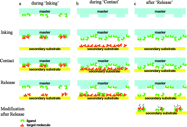 | ||
| Fig. 3 Schematic illustration of supramolecular interactions that take place (a) during inking, (b) during contact, and (c) after release. The common steps of contact-based methods are indicated on the left (inking, contact and release). | ||
3.1 Supramolecular interactions during inking
Supramolecular interactions during inking refer to the capture of molecules (ink) from inking solution through their complementary molecules which are already immobilized on the stamp. Here, as opposed to stamps defined by physical shape in μCP, the stamps inked through supramolecular forces transfer complementary molecules onto the secondary substrate. The key point of this approach is patterning the corresponding ligand molecules first as precursors, followed by the assembly of the final molecules. Since ligand molecules are more robust and simpler than the target biomolecules, the printing process will be more reliable and the biomolecules will be less damaged. It can also be expected that the biomolecules connected to the printed ligand will have more conformational freedom inducing higher activity compared to directly deposited biomolecules on surface since the ligand can act as a linker molecule. In addition, since the printed molecules also have the same recognition power, the printed substrate is open to further supramolecular modifications and can be used as a template as well.In order to enable this approach, two main conditions should be satisfied as following: (i) the interaction between the complementary units should be reversible by changing the given conditions such as temperature, electric field and pH, and (ii) the bonding between the substrate and bound molecules should be stronger than the supramolecular interaction between two complementary molecules during release.
Initially, the basics of affinity contact printing were demonstrated for the capture of proteins from solution and consequent μCP. Using mouse IgG, anti-mouse IgG was inked on a PDMS stamp and anti-mouse IgG was stamped onto a glass slide. The authors demonstrated the reuse of the stamp and high yields.28 Renault et al. utilized micro-wells and a micro-fluidic network to decorate an amino-derivatized PDMS stamp with different proteins and fabricated high resolution protein arrays (104 in 1 mm2) in parallel (Fig. 4).29 In those works, the dissociation of captured antibodies was achieved by a mechanical force. During the release step, the forces stabilizing the printed molecules onto the secondary substrate are van der Waals adhesion forces. Recently, Abbott et al. suggested the possibility of orienting proteins during the printing step and employing liquid crystals as means to investigate the orientation of the printed proteins.30,31
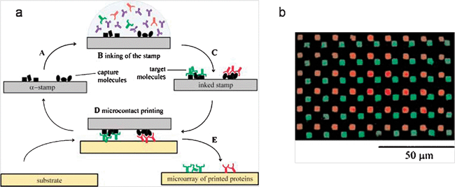 | ||
| Fig. 4 (a) Schematic illustration of the αCP procedure for printing two different proteins (b) the fluorescence micrograph of the printed pattern. The antigens immobilized on a template selectively capture the corresponding antibodies in solution (supramolecular inking) and the antibodies were transferred to another substrate.29 (Reproduced with permission from ref. 29, copyright 2002 Wiley-VCH Verlag GmbH & Co. KGaA). | ||
Using DNA as the ink in αCP offers several advantages due to the stability of DNA compared to proteins. Short DNA molecules (oligonucleotides shorter than 100-mer and commonly used for lithography) are smaller, simpler and better understood than proteins. This gives better printing resolution and less non-specific binding due to smaller van der Waals forces; thus the overall printing process is more reliable. Also, many chemical modifications can be introduced to DNA molecules; hence various chemistries and substrate systems can be utilized. The printed platforms can be used as a template for other purposes, for instance protein arrays can be fabricated by in situ transcription on/by the printed DNA microarrays.32,33
Recently, Crook’s34 and our35 group independently developed a truly parallel soft-material stamping technique to replicate DNA features from one surface onto another. Supramolecular nanostamping (SuNS), as referred by our group, is a printing technique based on the supramolecular interaction between complementary DNA (cDNA) strands for selective inking (Fig. 5). Once a template containing single stranded DNA (ssDNA) features is fabricated, the printing procedure of SuNS is composed of three steps: (1) ‘hybridization’ with cDNA modified with a chemical binding group toward a secondary substrate, (2) ‘contact’ with the secondary substrate, and (3) release after ‘dehybridization’ assisted by increased temperature or mechanical forces.
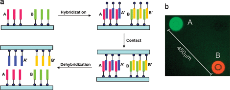 | ||
| Fig. 5 (a) Schematic illustration of the SuNS procedure.36 (Reproduced by the permission of The Royal Society of Chemistry http://dx.doi.org/10.1039/b602552h); (b) fluorescence micrograph of the two different simultaneously printed DNA sequences.35 (reprinted with permission from ref. 35, copyright 2005 American Chemical Society). | ||
SuNS is a versatile method, in terms of resolution, substrates it can be printed on and the initial master used to print. To date, using SuNS the substrates containing DNA features that range in size from a few tens of nanometers35,37–39 to hundreds of micrometers34,35,38,40–43 have been printed successfully. Several different types of methods have been employed to fabricate masters such as dip-pen nanolithography,35 achromatic interference lithography,35,38 optical lithography,43 electron-beam lithography,37 microfluidic techniques,43 spotting34,40–43 and simply self-assembly.39 The chemical nature of the substrates used as masters as well as secondary substrates has been varied widely including gold,35,37,39 PDMS,34,40–43 chemically modified glass,34,40–42 poly(methyl methacrylate),37 and poly(4-formyl-p-xylylene-co-p-xylylene).38 In addition, recently via chemical vapor deposition it has been shown that functional coatings were able to make a substrate printable through SuNS. Poly(4-formyl-p-xylylene-co-p-xylylene) deposited substrates such as glass, quartz, silicon, PDMS and poly(styrene) were demonstrated as successful media for SuNS rendering SuNS independent of the substrate.38 The contact issue remained a challenge for SuNS, shared with most of the other high resolution stamping techniques.44,45 To overcome this, recently we have developed liquid supramolecular nanostamping (LiSuNS) which eliminated the need for solid contact by pouring a liquid pre-polymer onto the master (Fig. 6).43 This pre-polymer is then polymerized, and after hardening lifted off.
 | ||
| Fig. 6 Schematic illustration of the LiSuNS procedure.43 (Reproduced with permission from ref. 43, copyright 2007 Wiley-VCH Verlag GmbH & Co. KGaA). | ||
Although, the main approach is similar, there are a few differences between our and Crook’s printing processes. In Crook’s group, the complementary DNA is biotin-functionalized and the secondary substrates are streptavidin-coated PDMS.34,40–42 Therefore, Crook’s group employs supramolecular interaction not only in inking but also during contact. To utilize the biotin-streptavidin interaction, the authors introduced a small amount of buffer or water before the template is placed on a secondary substrate. Additionally, the secondary substrate, streptavidin coated PDMS, has 10 μm deep trenches which are believed to help to drain the solution away from the interface to facilitate contact. After the contact, a mechanical force driving dehybridization is applied to separate two substrates. Using a similar method, the replication of RNA microarrays from DNA microarray templates was demonstrated as well.46 Furthermore, they introduced a ‘zip-code’ approach in which a template made of shorter primary DNA strands is hybridized with longer DNA strands containing a complementary part on their ends as shown Fig. 7.40 The master bearing spotted ‘zip codes’ is hybridized with DNA sequences which contains a ‘code sequence’ that is complementary to the ‘zip code’ and a functional sequence with a biotin moiety. ‘Zip codes’ dictate the location of these oligonucleotides and can be used with many different sequences.40
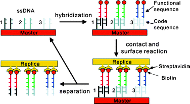 | ||
| Fig. 7 Schematic illustration of the ‘zip-code’ approach.40 (Reprinted with permission from ref. 40, copyright 2006 American Chemical Society). | ||
Crooks and co-workers also showed printing in situ synthesized cDNA through polymerase chain reactions (PCR) by using the primary DNA strands on the master as a template (Fig. 8).41 Immobilized ssDNA is first hybridized with its biotinylated complementary primer oligonucleotides which are then extended through PCR. Upon contact with a streptavidin coated PDMS, the cDNA stays on this secondary substrate. This result shows that any personalized DNA array can be used for printing its complementary array without pre-synthesizing the cDNA. They demonstrated the transfer of the in situ PCR products from a whole DNA microarray onto another substrate forming a complementary DNA microarray (Fig. 9).42
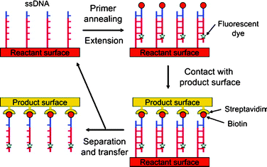 | ||
| Fig. 8 Schematic illustration of primer extension and subsequent printing procedure.41 (Reprinted with permission from ref. 41, copyright 2006 American Chemical Society). | ||
 | ||
| Fig. 9 Fluorescence micrographs of (a) the master after primer extension (DNA polymerase reaction) incorporated with the fluorescent dye (Cy3-dCTP), (b) master after printing, (c) replica surface after the transfer of the extended primer, (d) same as (c); but after the third round of primer extension and printing.42 (Reprinted with permission from ref. 42, copyright 2007 American Chemical Society). | ||
Yang and co-workers printed unmodified cDNA using a similar procedure.47 The ssDNA molecules are immobilized on an aminated PDMS stamp through electrostatic interaction between the negatively charged backbone of DNA and NH3+ groups on aminated PDMS. This stamp is hybridized with cDNA molecules and thereafter printed onto an amine-terminated glass slide. In this work, electrostatic interaction was employed to break the hydrogen bonds between complementary DNA molecules. The negatively charged backbone of the cDNA strands is attached to the amine groups, which exist as NH3+ (after protonation in neutral condition) on the glass slide and cDNA strands got transferred. At this time, the electrostatic attraction between cDNA and positively charged SAM on glass is stronger than the hydrogen bond between complementary DNA strands. More recently, poly(ethyleneimine) functionalized poly(methyl methacrylate) was used to transfer cDNA to aminated glass surface and features as small as 250 nm were successfully printed.48
Compared to all other DNA stamping techniques, the main advantage of SuNS is the ability to print multiple types of DNA in a single cycle. Especially, the recent improvement of Crook’s group, which is to enzymatically grow DNA strands with primer annealing and PCR, resulted in the replication of DNA microarrays truly scalable in a cost efficient way.42
Recently, Taussig et al. suggested a method for in situ protein synthesis, harnessing the supramolecular interaction between DNA and proteins.33 The authors demonstrated the printing of protein arrays from DNA microarray templates using cell-free protein synthesis. In this technique, a DNA template microarray, a filter-membrane containing required materials for cell-free protein expression and a protein capture slide, which form a sandwich (DNA array – membrane – protein capture slide) are incubated under protein expression conditions. Thereafter, the synthesized proteins are transferred through the membrane from the template array to the target slide via diffusion. This method allows a single DNA microarray to produce at least 20 protein arrays without individual protein expression, purification and spotting.
3.2 Supramolecular interactions during contact
In order to harness the supramolecular interactions during contact, the secondary substrate is modified to attract the ink molecules. These interactions, usually in the forms of electrostatic or van der Waals, are proposed to increase the stability,49–52 function,53 and control the printing area.54 Immobilizing corresponding ligands on the secondary substrate is a common approach in printing biomolecules such as printing avidin onto a polymeric substrate containing biotin moiety53 or vice versa34,40–42 and horseradish peroxide onto bovine serum albumin precursor layer on quartz.54Reinhoudt’s group utilizes supromolecular affinity by using an artificial host–guest system.49–52 The method is referred as ‘supramolecular microcontact printing’ and employs ‘printboards’ which are substrates containing a self-assembled monolayer (SAM) of molecules that have specific recognition sites for the target ink molecules. These printboards are composed of an invented host molecule β-cyclodextrin (β-CD) which shows affinity to small hydrophobic molecules and is modified with heptathioether chains to form SAMs on gold surfaces. In general, SAMs of the host molecule (β-CD) are prepared on gold-on-silica substrates, and ink molecules containing hydrophobic guest moiety such as an adamantyl group or a p-tert-butylphenyl group are printed on the boards through μCP or other lithography techniques. These printed patterns remained stable for a longer time or even after rinsing with buffer solutions compared to patterns on non-‘printboard’ substrates such as –OH terminated SAM or poly(ethylene glycol) coated substrates (Fig. 10).52 This result implies higher stability of printed patterns due to the strong interaction between the designed host–guest molecules. Moreover, through attaching small linkers by microcontact printing, streptavidin and biotinylated protein were sequentially immobilized on β-CD and this structure was shown to specifically adsorb Fc fragment of human immunoglobin G (IgG-Fc).55 In the same work, instead of IgG-Fc whole antibodies were used as well and utilized for counting lymphocytes.55
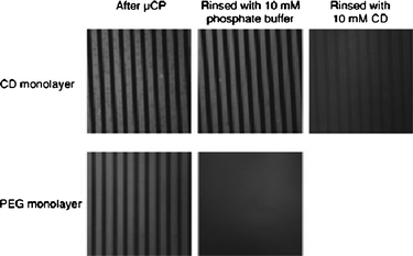 | ||
| Fig. 10 Fluorescence micrographs of printed “guests”(150 × 150 μm2), showing the stability difference between printing on “printboard” containing “host” molecules (β-cyclodextrin) by supramolecular lithography (top) and printing on poly(ethylene glycol) monolayer (bottom).52 (Reproduced with permission from ref. 52, copyright 2005 Wiley-VCH Verlag GmbH & Co. KGaA). | ||
3.3 Supramolecular interactions after release
The most common use of supramolecular interaction is employing supramolecular modification on the printed pattern after release. This approach involves patterning the corresponding ligand molecules first as precursors through μCP and consecutively assembling final molecules on the same substrate.The most broadly studied example is making avidin/streptavidin pattern by exploiting the specific interaction between biotin – avidin/streptavidin.55–59 One strategy is to first print SAMs containing reactive functional groups and decorate these features with biotin.56 The Chilkoti group introduced microstamping on an activated polymer surfaces (MAPS) which involves introducing carboxylic acid groups on polymeric surfaces (poly(ethylene), poly(styrene), poly(methyl methacrylate), and poly(ethylene terephthalate)) and reacting these with aminated biotin.57,58 Other groups have also employed similar strategies to have reactive groups on the surface such as surface hydrolysis of poly(glycolic acid) to have carboxylic acid.60 Another method is to use chemical vapor deposition polymerization of functionalized polymers to react with biotin.59
Conclusion
Contact-based methods are expected to be more widespread due to the potential solution of the cost issues. In this review, we aimed to give background information on contact-based techniques applicable to biomaterials. Supramolecular interactions are likely to improve current printing techniques; thus we believe the direction of the research will be more towards harnessing and investing on biomolecular systems which can form reversible interactions among them as well as synthesis of these biomolecules on the spot before printing. One of the key features of contact-based methods is some forms are capable of transferring chemical and spatial information; an innovative feature that will find many applications in biomolecular devices. The next challenge for this field will be adding another dimension: transferring biomolecules with specific 3-D shapes such as aptamers and engineered scaffold proteins.References
- B. D. Gates, Q. Xu, M. Stewart, D. Ryan, C. G. Willson and G. M. Whitesides, Chem. Rev., 2005, 105, 1171 CrossRef CAS.
- M. J. Heller, Annu. Rev. Biomed. Eng., 2002, 4, 129–153 CrossRef CAS.
- H. Zhu and M. Snyder, Curr. Opin. Chem. Biol., 2003, 7, 55–63 CrossRef CAS.
- M. Dufva, Biomol. Eng., 2005, 22, 173–184 CrossRef CAS.
- G. MacBeath and S. L. Schreiber, Science, 2000, 289, 1760–1763 CAS.
- Y. Xia and G. M. Whitesides, Annu. Rev. Mater. Sci., 1998, 28, 153–184 CrossRef CAS.
- A. P. Quist, E. Pavlovic and S. Oscarsson, Anal. Bioanal. Chem., 2005, 381, 591–600 CrossRef CAS.
- E. Delamarche, H. Schmid, A. Bietsch, N. B. Larsen, H. Rothuizen, B. Michel and H. Biebuyck, J. Phys. Chem. B, 1998, 102, 3324–3334 CrossRef CAS.
- B. A. Langowski and K. E. Uhrich, Langmuir, 2005, 21, 6366–6372 CrossRef CAS.
- E. Delamarche, C. Donzel, F. S. Kamounah, H. Wolf, M. Geissler, R. Stutz, P. Schmidt-Winkel, B. Michel, H. J. Mathieu and K. Schaumburg, Langmuir, 2003, 19, 8749–8758 CrossRef CAS.
- S. A. Lange, V. Benes, D. P. Kern, J. K. H. Horber and A. Bernard, Anal. Chem., 2004, 76, 1641–1647 CrossRef CAS.
- D. I. Rozkiewicz, W. Brugman, R. M. Kerkhoven, B. J. Ravoo and D. N. Reinhoudt, J. Am. Chem. Soc., 2007, 129, 11593–11599 CrossRef CAS.
- L. Xu, L. Robert, Q. Ouyang, F. Taddei, Y. Chen, A. B. Lindner and D. Baigl, Nano Lett., 2007, 7, 2068–2072 CrossRef CAS.
- C. Xu, P. Taylor, M. Ersoz, P. D. I. Fletcher and V. N. Paunov, J. Mater. Chem., 2003, 13, 3044–3048 RSC.
- J. L. Tan, J. Tien and C. S. Chen, Langmuir, 2002, 18, 519–523 CrossRef CAS.
- H. D. Inerowicz, S. Howell, F. E. Regnier and R. Reifenberger, Langmuir, 2002, 18, 5263–5268 CrossRef CAS.
- M. Mrksich, L. E. Dike, J. Tien, D. E. Ingber and G. M. Whitesides, Exp. Cell Res., 1997, 235, 305–313 CrossRef CAS.
- A. Bernard, J. P. Renault, B. Michel, H. R. Bosshard and E. Delamarche, Adv. Mater., 2000, 12, 1067–1070 CrossRef CAS.
- J. P. Renault, A. Bernard, A. Bietsch, B. Michel, H. R. Bosshard, E. Delamarche, M. Kreiter, B. Hecht and U. P. Wild, J. Phys. Chem. B, 2003, 107, 703–711 CrossRef CAS.
- K. G. Sharp, G. S. Blackman, N. J. Glassmaker, A. Jagota and C.-Y. Hui, Langmuir, 2004, 20, 6430–6438 CrossRef CAS.
- T. Pompe, A. Fery, S. Herminghaus, A. Kriele, H. Lorenz and J. P. Kotthaus, Langmuir, 1999, 15, 2398–2401 CrossRef CAS.
- B. Michel, A. Bernard, A. Bietsch, E. Delamarche, M. Geissler, D. Juncker, H. Kind, J. P. Renault, H. Rothuizen, H. Schmid, P. Schmidt-Winkel, R. Stutz and H. Wolf, IBM Journal of Research and Development, 2001, 45, 697–719 Search PubMed.
- H. Schmid and B. Michel, Macromolecules, 2000, 33, 3042–3049 CrossRef CAS.
- T. W. Odom, J. C. Love, D. B. Wolfe, K. E. Paul and G. M. Whitesides, Langmuir, 2002, 18, 5314–5320 CrossRef CAS.
- D. Trimbach, K. Feldman, N. D. Spencer, D. J. Broer and C. W. M. Bastiaansen, Langmuir, 2003, 19, 10957–10961 CrossRef CAS.
- X. Duan, V. B. Sadhu, A. Perl, M. Pter, D. N. Reinhoudt and J. Huskens, Langmuir, 2008, 24, 3621–3627 CrossRef CAS.
- J. Chalmeau, C. Thibault, F. Carcenac and C. Vieu, Appl. Phys. Lett., 2008, 93, 133901–133903 CrossRef.
- A. Bernard, D. Fitzli, P. Sonderegger, E. Delamarche, B. Michel, H. R. Bosshard and H. Biebuyck, Nat. Biotechnol., 2001, 19, 866–869 CrossRef CAS.
- J. P. Renault, A. Bernard, D. Juncker, B. Michel, H. R. Bosshard and E. Delamarche, Angew. Chem., Int. Ed., 2002, 41, 2320–2323 CrossRef CAS.
- M. L. Tingey, S. Wilyana, E. J. Snodgrass and N. L. Abbott, Langmuir, 2004, 20, 6818–6826 CrossRef CAS.
- M. L. Tingey, E. J. Snodgrass and N. L. Abbott, Adv. Mater., 2004, 16, 1331–1336 CrossRef CAS.
- M. He, O. Stoevesandt and M. J. Taussig, Curr. Opin. Biotechnol., 2008, 19, 4–9 CrossRef CAS.
- M. He, O. Stoevesandt, E. A. Palmer, F. Khan, O. Ericsson and M. J. Taussig, Nat. Methods, 2008, 5, 175 CrossRef CAS.
- H. Lin, L. Sun and R. M. Crooks, J. Am. Chem. Soc., 2005, 127, 11210–11211 CrossRef CAS.
- A. A. Yu, T. A. Savas, G. S. Taylor, A. Guiseppe-Elie, H. I. Smith and F. Stellacci, Nano Lett., 2005, 5, 1061–1064 CrossRef CAS.
- A. A. Yu and F. Stellacci, J. Mater. Chem., 2006, 16, 2868–2870 RSC.
- A. A. Yu, T. Savas, S. Cabrini, E. diFabrizio, H. I. Smith and F. Stellacci, J. Am. Chem. Soc., 2005, 127, 16774–16775 CrossRef CAS.
- S. Thévenet, H.-Y. Chen, J. Lahann and F. Stellacci, Adv. Mater., 2007, 19, 4333–4337 CrossRef CAS.
- O. Akbulut, J.-M. Jung, R. D. Bennett, Y. Hu, H.-T. Jung, R. E. Cohen, A. M. Mayes and F. Stellacci, Nano Lett., 2007, 7, 3493–3498 CrossRef CAS.
- H. Lin, J. Kim, L. Sun and R. M. Crooks, J. Am. Chem. Soc., 2006, 128, 3268–3272 CrossRef CAS.
- J. Kim and R. M. Crooks, J. Am. Chem. Soc., 2006, 128, 12076–12077 CrossRef CAS.
- J. Kim and R. M. Crooks, Anal. Chem., 2007, 79, 7267–7274 CrossRef CAS.
- A. A. Yu and F. Stellacci, Adv. Mater., 2007, 19, 4338–4342 CrossRef CAS.
- D. J. Resnick, W. J. Dauksher, D. Mancini, K. J. Nordquist, T. C. Bailey, S. Johnson, N. Stacey, J. G. Ekerdt, C. G. Willson, S. V. Sreenivasan and N. Schumaker, J. Vac. Sci. Technol., B, 2003, 21, 2624–2631 CrossRef CAS.
- L. J. Guo, J. Phys. D: Appl. Phys., 2004, 37, R123–R141 CrossRef CAS.
- J. Kim and R. M. Crooks, Anal. Chem., 2007, 79, 8994–8999 CrossRef CAS.
- H. Tan, S. Huang and K.-L. Yang, Langmuir, 2007, 23, 8607–8613 CrossRef CAS.
- Y. Wang, S. H. Goh, X. Bi and K.-L. Yang, J. Colloid Interface Sci., 2009, 333, 188–194 CrossRef CAS.
- T. Auletta, B. Dordi, A. Mulder, A. Sartori, S. Onclin, C. M. Bruinink, M. Peter, C. A. Nijhuis, H. Beijleveld, H. Schonherr, G. JuliusVancso, A. Casnati, R. Ungaro, B. J. Ravoo, J. Huskens and D. N. Reinhoudt, Angew. Chem., Int. Ed., 2004, 43, 369–373 CrossRef CAS.
- C. M. Bruinink, C. A. Nijhuis, M. Peter, B. Dordi, O. Crespo-Biel, T. Auletta, A. Mulder, H. Schonherr, G. J. Vancso, J. Huskens and D. N. Reinhoudt, Chem.–Eur. J., 2005, 11, 3988–3996 CrossRef CAS.
- O. Crespo-Biel, M. Peter, C. M. Bruinink, Bart Jan Ravoo, D. N. Reinhoudt and J. Huskens, Chem.–Eur. J., 2005, 11, 2426–2432 CrossRef.
- A. Mulder, S. Onclin, M. Peter, J. P. Hoogenboom, H. Beijleveld, J. t. Maat, M. F. Garcia-Parajo, B. J. Ravoo, J. Huskens, N. F. v. Hulst and D. N. Reinhoudt, Small, 2005, 1, 242–253 CrossRef CAS.
- N. Patel, R. Bhandari, K. M. Shakesheff, S. M. Caninizzaro, M. C. Davies, R. Langer, C. J. Roberts, S. J. B. Tendler and P. M. Williams, J. Biomater. Sci., Polym. Ed., 2000, 11, 319–331 CrossRef CAS.
- B. Wang, J. Feng and C. Y. Gao, Macromol. Biosci., 2005, 5, 767–774 CrossRef CAS.
- M. J. W. Ludden, X. Li, J. Greve, A. v. Amerongen, M. Escalante, V. Subramaniam, D. N. Reinhoudt and J. Huskens, J. Am. Chem. Soc., 2008, 130, 6964–6973 CrossRef CAS.
- J. Lahiri, E. Ostuni and G. M. Whitesides, Langmuir, 1999, 15, 2055–2060 CrossRef CAS.
- J. Hyun, Y. Zhu, A. Liebmann-Vinson, J. Thomas P. Beebe and A. Chilkoti, Langmuir, 2001, 17, 6358–6367 CrossRef CAS.
- Z. Yang, A. M. Belu, A. Liebmann-Vinson, H. Sugg and A. Chilkoti, Langmuir, 2000, 16, 7482–7492 CrossRef CAS.
- J. Lahann, M. Balcells, T. Rodon, J. Lee, I. S. Choi, K. F. Jensen and R. Langer, Langmuir, 2002, 18, 3632–3638 CrossRef CAS.
- K.-B. Lee, D. J. Kim, Z.-W. Lee, S. I. Woo and I. S. Choi, Langmuir, 2004, 20, 2531–2535 CrossRef CAS.
| This journal is © The Royal Society of Chemistry 2010 |
