Chemistry and materials options of sustainable carbon materials made by hydrothermal carbonization
Maria-Magdalena Titirici* and Markus Antonietti
Max Planck Institute of Colloids and Interfaces, Am Mühlenberg 14476, Golm, Germany. E-mail: magdalena.titirici@mpikg.mpg.de; Fax: +49 (0)331 567 95; Tel: +49 (0)331 567 9508
First published on 24th September 2009
Abstract
The production of functional nanostructured materials starting from cheap natural precursors using environmentally friendly processes is a highly attractive subject in material chemistry today. Recently, much attention has been focused on the use of plant biomass to produce functional carbonaceous materials, encompassing economic, environmental and social issues. Besides the classical route to produce activated carbons from agricultural side products, the hydrothermal carbonization (HTC) process shows clear advantages in that it can generate a variety of cheap and sustainable carbonaceous materials with attractive nanostructure and functionalization patterns for a wide range of applications. In this tutorial review we present the latest developments in this traditional but recently invigorated technique. It will be shown that HTC does not only access carbonaceous materials under comparatively mild hydrothermal conditions, but also replaces the more technical and structurally well-defined charring by a controlled chemical process. It will be shown that this makes it possible to tailor the final structure with the tools of colloid and polymer science, leading to very different morphologies with miscellaneous applications, including modern carbon nanocomposites and hybrids.
 Maria-Magdalena Titirici | Maria-Magdalena Titirici graduated in 1999 from Bucharest University. Afterwards, she conducted her PhD studies (with Dr Börje Sellergren) first at the University of Mainz and later on at the University of Dortmund in the field of Molecularly Imprinted Polymers. In 2005 she joined Prof. Antonietti’s group as a postdoctoral researcher at the Max-Planck Institute of Colloids and Interfaces. Currently Maria-Magdalena Titirici is leading the “Sustainable Functional Carbonaceous and Polymeric Materials’’ group in the same research institute; her scientific interests include sustainable green chemistry, carbon and mesoporous materials, molecular recognition and development of novel stationary phases for chromatography. |
 Markus Antonietti | Markus Antonietti is a Scientific Member of the Max Planck Society and is working in the MPI of Colloids and Interfaces/Golm. He completed his polymer and physical chemistry education in Mainz with H. Sillescu and moved via Marburg to his current occupation. His current research covers various aspects of polymer and hybrid materials, but he is also active in higher scientific education and various other aspects of human culture. |
1. Introduction
Until recently, the synthesis of nanostructured carbon materials, a hot topic of material synthesis, was usually based on very harsh conditions such as electric-arc discharge techniques,1 chemical vapor deposition,2 catalytic pyrolysis of organic compounds,3 and similar techniques. In addition (excluding activated carbons), only a little research has been done to synthesize and recognize the structure of carbon materials based on natural resources. This is somehow hard to understand, as carbon structure synthesis has been done from the beginning of civilization on the basis of biomass, with the petrochemical age being only a late deviation. An approach towards advanced carbon synthesis based on renewable resources would be a significant operation, as the final products represent a significant proportion of modern materials.The concept of Sustainable Chemistry represents an area of innovation which not only preserves resources, but also stands for a development process of the chemical industry and chemistry as such. Sustainable Chemistry aspires to raise the value of less dangerous chemicals at the same time as it tries to produce high-quality products in an environmentally friendly manner from preferably renewable resources.
It will be shown in this article that hydrothermal carbonization (HTC) can turn into a model case for such a process: low value and widely available biomass can be converted into interesting carbon nanostructures using environmentally friendly steps. These low cost nanostructured carbon materials can then be designed for applications in crucial fields such as separation, energy conversion and catalysis. Besides controlling the chemistry of carbonization (i.e. C–C-linkage), two other important prerequisites for the achievement of useful properties are the control over morphology both at nano- and macroscale and the control over functionality by chemical means in hydrothermal carbonization.
The natural process of peat or coal formation is presumably not mainly biological, but chemical in its nature and takes place on the timescale of some hundreds (peat) to millions (black coal) of years. As “coaling” is a rather natural experiment, there are countless trials in the literature to chemically imitate carbon formation from carbohydrates with faster chemical processes, and hydrothermal carbonization is especially promising. The first experiments of the scientific age were presumably carried out by Bergius, who described in 1913 the hydrothermal transformation of cellulose into coal like materials.4 More systematic investigations were performed by Berl and Schmidt in 1932 who varied the source of the biomass and treated the different samples in the presence of water at temperatures between 150 °C and 350 °C.5 These two authors summarized with a series of papers in 1932 the knowledge about the emergence of coal of those days. Later, Schuhmacher, Huntjens and van Krevelen analyzed the influence of pH on the outcome of the reaction and found serious differences in the decomposition schemes, mainly based on mean composition data.6 A review of the current knowledge on coal structure and its origin is found in ref. 7.
Obviously the technique of hydrothermal carbonization is not new, however it was only recently that this technique was rediscovered by several working groups.8–10 Since then, it has become an important technique for the production of various carbonaceous materials and hybrids, usually applied at mild temperatures (<200 °C) and in pure water inside closed recipients and under self generated pressure.
Here, we intend to review the latest advances in the synthesis of functional carbonaceous materials from different biomasses or biomass derived sources via the HTC process. In the first part of this review we will focus on general aspects of hydrothermal carbonization, using either carbohydrates or complex biomass to control structure formation in the presence of various catalysts and/or templates. In the second part, we will focus on some of the most promising applications of the carbonaceous and hybrid materials obtained using hydrothermal carbonization.
2. Hydrothermal synthesis of carbonaceous materials
2.1 From pure carbohydrates
In order to gain some information about the fundamentals of the hydrothermal carbonization process, the hydrothermal carbonization of different carbohydrates and carbohydrate products was examined.11,12 For instance, hydrothermal carbons synthesized from diverse biomass (glucose, xylose, maltose, sucrose, amylopectin, starch) and biomass derivatives (hydroxymethylfurfural (HMF) and furfural) were treated under hydrothermal conditions at 180 °C and were analyzed with respect to their chemical and morphological structures by SEM, 13C solid-state NMR and elemental analysis. This was combined with GC-MS experiments on residual liquor solutions to analyze side products and unreacted species. It was demonstrated that under those conditions, all hexose sugars, no matter what their complexity, degrade into (hydroxymethyl)furfural, which finally condenses to a carbon-like material having morphological similarities and the same chemical and structural composition practically throughout all starting products. By contrast, xylose derivatives dehydrate into furfural, which in turn reacts to provide carbon structures very similar to those obtained from pure furfural, which are however different from the hexose products (e.g., a higher content of carbon aromatic structures).13C solid-state NMR also showed that starting from more complex, “real life” biomass instead of clean sugars does not change the outcome of the hydrothermal carbonization reaction, and remarkable similarities between the products of homologous series do occur, with respect to both morphology and local structural connectivity. Basically, the hydrothermal carbonization reaction takes place in three important steps: (1) dehydration of the carbohydrate to (hydroxymethyl)furfural; (2) polymerization towards polyfurans; (3) carbonization via further intermolecular dehydration.
The hydrothermal carbons obtained in the end from soluble, non-structural carbohydrates are micrometer sized, spherically shaped particle dispersions, containing an sp2 hybridized backbone (also responsible for the brown to black color) decorated with numerous polar oxygenated functionalities still remaining from the original carbohydrate. The presence of these surface groups offers the possibility of further functionalization and makes the materials more hydrophilic and highly dispersible in water. The size of the final particles depends mainly on the carbonization time and precursor concentration inside the autoclave, as well as additives and stabilizers potentially to be added to the primary reaction recipe. Some SEM pictures obtained from various carbohydrate sources are given in Fig. 1. A typical weight yield for the carbon material is about 50 wt% of the initial amount of carbohydrate; this corresponds to a molar conversion of higher than 90%.
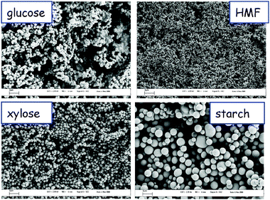 | ||
| Fig. 1 Scanning electron micrographs of various hydrothermal carbons obtained from different carbohydrate sources (scale bar 2 μm) (reproduced from ref. 11 with the permission of The Royal Society of Chemistry). | ||
It was also found that the presence of metal ions can effectively accelerate the hydrothermal carbonization of starch, which shortens the reaction time to some hours. Thus, iron ions and iron oxide nanoparticles were shown to effectively catalyze the hydrothermal carbonization of starch, but also complete rice grains under mild conditions (≤200 °C) and also had a significant influence on the morphology of the formed carbon nanomaterials.9 In the presence of Fe2+ ions, both hollow and massive carbon microspheres could be obtained. In contrast, the presence of Fe2O3 nanoparticles leads to very fine, rope-like carbon nanostructures, reminiscent of disordered nanotubes.
The first mesoporous hydrothermal carbons were produced by performing the hydrothermal carbonization in the presence of nanostructures silica templates.8 Thus, it was discovered that it is important to match the polarity of the template surface with that of the carbon precursor. Scheme 1 illustrates that silica templates with a moderately hydrophobic surface lead to hollow carbon spheres, whereas demixing or macroporous carbon casts occur in the presence of templates of a more hydrophilic or hydrophobic surface. For a mesoporous template, mesoporous carbon shells are obtained after removal of the template, with the whole carbonaceous structure composed of ca. 8–16 nm globular carbon nanoparticles. Furthermore, the moderately hydrophobic silica templates filled with 60 wt% carbon precursor resulted in mesoporous carbonaceous microspheres whereas application of 30 wt% carbon precursor gave only small carbon spherules (6–10 nm in size), owing to the lack of interconnectivity between particles in the coating. This nicely illustrates that the carbon coating process operates “patch-wise”via stable colloidal intermediates. For non-porous templates, hollow carbonaceous spheres with a robust carbon coating are observed.
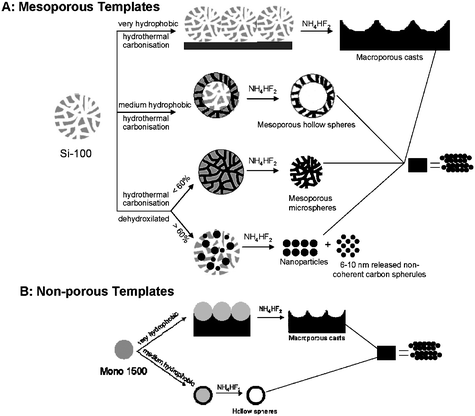 | ||
| Scheme 1 Schematic representation of the hydrothermal carbonization process in the presence of silica templates with different polarities, leading to various carbon morphologies (reproduced from ref. 8 with the permission of Wiley-VCH). | ||
The effective weight yield of the materials obtained via the “hard templating” route is relatively low and depends on the amount of sacrificial template used and its porosity. Typically, using 1 g of silica template with a total pore volume of 1 mL/g about 0.2–0.3 g of high purity HTC replica (∼70% C) is obtained.
After finding the optimal hydrothermal carbon replication conditions for mesoporous silica, a replica of an ordered SBA-15 material has also been successfully produced.13 In this report, the residing functional groups could also be successfully converted into amino groups. Some TEM pictures of these mesoporous ordered hydrophilic materials together with the FT-IR spectra proving the presence of the amino groups on the surface of these materials are given in Fig. 2.
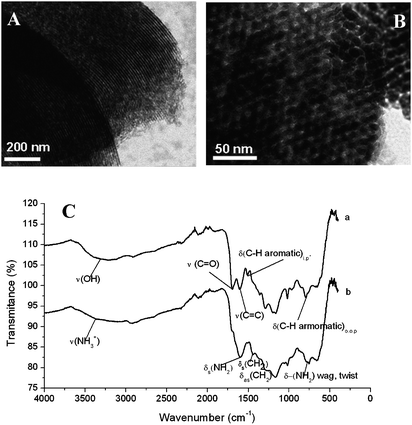 | ||
| Fig. 2 (A) TEM micrograph of the carbon replica obtained by 100% pore filling of SBA-15 template; (B) TEM micrograph of the carbon replica obtained after 25% pore filling of SBA-15 template; (C) FT-IR of the bare carbon replica (a) and the amino-post functionalized material (b) (reproduced from ref. 13 with the permission of The Royal Society of Chemistry). | ||
The perfection of this nanocoating process following free shapes in three dimensions is nicely illustrated by the coating of nanowires. Uniform carbonaceous nanofibers with high aspect ratio could be produced using the HTC of glucose in the presence of Te nanowires of only some nanometers in diameter.14 Well-defined ultralong carbon nanofibers are made by removing the Te nanowires from the Te@carbon-rich composite nanocables. The carbonaceous nanofibers have an average diameter of ca. 50 nm and are up to tens or hundreds of micrometers in length (Fig. 3). Also here, the particulate character of the coating process is nicely reflected in the nanoscale roughness of the carbon fibers.
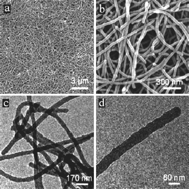 | ||
| Fig. 3 (a) A general view of the nanofibers and (b) an enlarged SEM image. (c)–(d) TEM images of the nanofibers. Reproduced from ref. 14 with the kind permission of the American Chemical Society. | ||
Yu also reported on the production of hollow carbon spheres using the microwave induced hydrothermal treatment of carbohydrates (starch) in the presence of H2SeO3 leading first to the production of core–shell Se/C colloids. After removing the Se core by thermal treatment, hollow C capsules were formed.15
Li et al. reported first on the decoration of hydrothermal carbon spheres obtained from glucose with noble metal nanoparticles.17 They used the reactivity of as-prepared carbon microspheres to load silver and palladium nanoparticles onto their surfaces via room-temperature surface reduction or by the reflux method. Furthermore, it was also demonstrated that these carbon spheres have the ability to encapsulate nanoparticles in their cores with retention of the surface functional groups. Nanoparticles of gold and silver could be encapsulated in carbon by in situ hydrothermal reduction of noble-metal ions with glucose, or by using silver nanoparticles as nuclei for subsequent formation of carbon spheres. Some TEM images of such exciting hybrid materials are shown in Fig. 4.
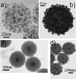 | ||
| Fig. 4 (a) Carbon spheres loaded with silver nanoparticles at room temperature. (b) Carbon spheres loaded with palladium nanoparticles by the reflux method. (c) Silver-cored carbon spheres from encapsulation of silver nanoparticle seeds. (d) Layered structure with a silver core, a platinum shell, and a carbon interlayer, formed by seed based encapsulation followed by the reflux method (reproduced from ref. 17 with the permission of Wiley-VCH). | ||
The production of Ag@carbon nanocables was reported by Yu et al.18 In this case the authors used the hydrothermal carbonization of starch in the presence of AgNO3 leading to the one-step formation of carbon/Ag hybrid nanocables.
Such silver–carbon nanocables can have a length as long as 10 mm and overall diameters of 1 micron with a 200–250 nm silver lining. When made at higher concentrations, they tend to fuse with each other (Fig. 5a and b).
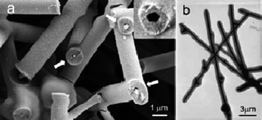 | ||
| Fig. 5 (a) Typical SEM image of the nanoscale with encapsulated, silver nanowires. The insert shows an incompletely drilled tube with a pentagonal cross-section. (b) TEM image of typical silver–carbon nanocables formed after treating at 160 °C for 12 h: 5 g starch, 5 mmol AgNO3, pH 4 (reproduced from ref. 18 with the permission of Wiley-VCH). | ||
This method was extended for the polyvinyl alcohol (PVA)-assisted synthesis of flexible noble metal (Ag, Cu)@carbon-rich composite submicrocables,19,20 as well as large-scale production of Te@carbon nanocables14 directed by Te nanowires based on the HTC process.
Interesting details on materials interfaces are disclosed for the model system SiO2@C microspheres.21 Uniform and functionalized SiO2@C microspheres were synthesized with glucose as carbon precursor and silica spheres as cores. A surprising feature of the product is the finding of a vacant region between the carbon shells and silica cores. Such SiO2@C core–shell spheres can be further applied to prepare SiO2@C@SiO2, SiO2@SiO2 with a vacancy between the two SiO2 structures, noble metal nanoparticles loaded SiO2@C core–shell spheres, and hollow carbon capsules through different synthetic, post-treatment, or etching processes. It was found that the surfaces of SiO2@C microspheres are highly functionalized, display excellent chemical reactivity, and are able to reduce in situ noble-metal ions to nanoparticles and bind them onto the surface.
It was therefore straightforward to apply HTC by including sustainable nitrogen sources with appropriate co-reactivity. The synthesis of well defined carbonaceous nanostructures with significant nitrogen-doping level and a developed sponge-like mesopore system was recently demonstrated by using hydrothermal treatment at 180 °C of glucose in the presence of ovalbumin.27 This simple process at first provides a unique and sustainable pathway to control the primary particle stability in hydrothermal carbonization, resulting in the formation of nanometer-sized sponge scaffolds composed of spherical particles (20–50 nm) (Fig. 6). Another advantage is that the protein efficiently introduces structural nitrogen (as much as 8 wt%) into the carbonaceous scaffold, which is favorable for catalysis, adsorption, but also to increase the oxidation stability of engineering carbons.
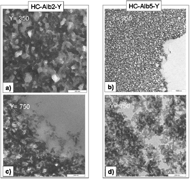 | ||
| Fig. 6 TEM images for higher temperature samples HC-AlbX-Y, X = 2.5. Y (= 350, 750) indicates the calcination temperature. Scale bar is 200 nm. | ||
Classical characterization methods (nitrogen adsorption–desorption, TEM, SEM, FTIR, XPS and elemental analysis) were used to describe the resulting porous carbon structures. Temperature-dependent experiments have shown that all the various materials kept the nitrogen content almost unchanged up to 950 °C, while the thermal and oxidation stability was found to be significantly increased as compared to pure carbon based hydrothermal scaffolds. Last but not least, it has to be repeated that the whole material synthesis process occurs in a remarkably energy- and atom-efficient fashion from cheap and sustainable resources, as temperatures employed in the first step remain below 200 °C and neither metals nor surfactants have been used to catalyze and control the reaction.
Another approach our group took towards the synthesis of nitrogen rich carbons under green and sustainable conditions is the direct hydrothermal carbonization of nitrogen containing carbohydrates, such as glucosamine or chitosane.28 Again, carbonaceous materials with a high content of nitrogen that could also be maintained at higher carbonization temperatures were obtained.
2.2 From complex biomass
At the same time as the understanding of some basics of hydrothermal carbonization was obtained using pure carbohydrate models, the synthesis of hydrothermal carbon materials using raw biomass was embarked upon.In contrast to previous work8,11,13 which focused on clean and simple carbohydrate sources, our group analyzed if complex biomass—hydrothermally carbonized—can also be directed to complex structural motifs with distinct surface polarities. Ideally, one can use for this purpose the structures and functionalization components which are already included in the biomass. We specifically selected waste biomass for material synthesis, starting products which are known to be hard to use otherwise, rich in ternary components, and applied different HTC conditions.29 That way, one can avoid the food–raw materials competition, a prerequisite we regard as key for the development of a new sustainable chemistry.
Diverse biomass compounds were heated in sealed autoclaves in the presence of acids as catalyst at 200 °C for 16 h, and essentially two kinds of reaction scenarios were found.30 For soft biomass and non textured biomass, hydrophilic and water-dispersible carbonaceous nanoparticles in the size range of 20–200 nm were obtained. Their occurrence as spherical particles indicates that the soft biomass was first liquefied, then carbonized, which offers possibilities to chemically interfere with this complex process discussed above. Such carbon nanoparticles might represent an alternative to the current carbon blacks made by (much less sustainable) flame processes, but due to the excellent price base might also end up in novel applications, such as an reinforcement in concrete or pavements.
For hard biomass made from crystalline cellulose, an “inverted” structure was found, with the carbon being the continuous phase, penetrated by a sponge like continuous system of nanopores (representing the majority volume). Also these products are hydrophilic due to the presence of ca. 20 wt% functional oxygenated groups, and can be easily wetted with water. Such structures are ideal for water binding, capillarity, and ion exchange. By simple chemical means, the product is practically indistinguishable from the carbonaceous fraction of soil, but structurally much better defined. These morphologies of hydrothermal carbon (HC) from both “soft” and “hard” biomass are shown in Fig. 7.
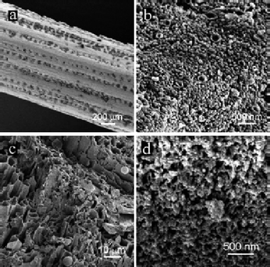 | ||
| Fig. 7 HRSEM of pine needles (a) before and (b) after being hydrothermally carbonized at 200 °C for 12 h; (c) low-magnification SEM overview of an HTC-treated oak leaf; (d) high-magnification picture of the same HTC-treated oak leaf indicating its nanostructure. (Reproduced from ref. 29 with the permission of the American Chemical Society). | ||
It has already been reported that Fe2+ ions can effectively catalyze the carbonization of complete rice grains in the HTC process.9 The insoluble part of the grain forms larger, porous carbonized species, and preserves the primary grain structure, which is different along the body of the grain. Interestingly, the majority of the 5 mm long carbon grains are composed of hollow carbon sheets and separated carbon nanofibers, keeping the primary fibrous structure of the rice tissue on the nanometer scale (Fig. 8c). The soluble fraction of the rice grain forms carbon microspheres, which are well separated from the grains and only partly adhered at their surface (Fig. 8d).
 | ||
| Fig. 8 (a) Coexistence of carbon spheres and a carbonized, microstructured biological tissue; (b) magnified SEM image indicating that the 3D tissue is indeed built up from well-defined carbon nanofibers; (c) organized carbon scaffold replicating a different biological motif of the nonsoluble carbohydrates in rice; (d) pure carbon spheres collected from the solution generated from the soluble polysaccharides. (Reproduced from ref. 9 with the permission of Wiley-VCH). | ||
2.3 Applications of hydrothermal carbons
The most appealing feature of hydrothermal carbonization is the fact that it represents an easy, green and scalable process allowing the production of various carbon and hybrid nanostructures with practical applications on a price base which is mostly well below any number of corresponding petrochemical processes. Even at this early stage, HTC materials have already found numerous applications in relevant fields of modern materials device manufacturing and the chemical industry such as catalysis, water purification, energy storage and CO2 sequestration. In the following paragraphs we will summarize some of the most remarkable examples where HTC based materials have proved to be not only sustainable, but to possess extraordinary properties which in some cases surpass those of current “gold standards”.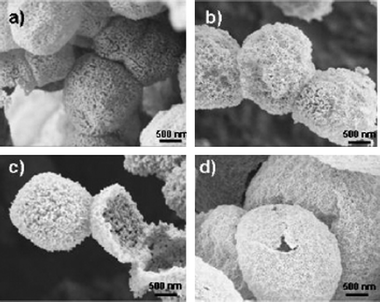 | ||
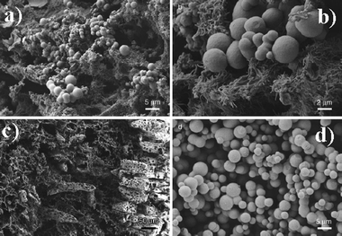
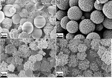
| Fig. 9 SEM images of (a) NiO, (b) Co3O4, (c) CeO2, and (d) MgO hollow spheres (reproduced from ref. 31 with the permission of the American Chemical Society). | ||
An analogous procedure for the production of TiO2 hollow spheres was reported by Shi et al.32 The authors first prepared hydrothermal carbon spheres using the hydrothermal carbonization of glucose. Afterwards, they took advantage of the oxygenated functional groups on the surface of the carbon spheres and dispersed the carbon spheres in a toluene solution of titanium tetraisopropoxide. Hydrolysis of the orthoesters by –OH on the surface layer generated a condensed glassy layer of amorphous TiO2. After thermal treatment under vacuum at 450 °C for 2 h, TiO2 of this composite crystallized, and the TiO2/C-v sample showed well-discerned characteristic peaks of anatase.
Using the salt addition/inclusion-scheme, mesoporous SnO2 microspheres were also prepared by hydrothermal treatment of pre-formed 3–7 nm sized SnO2 nanoparticles in the presence of glucose.33 Throughout the formation of carbon spheres, the nanoparticles are homogeneously incorporated into the carbon matrix, as can be seen in Fig. 10a, and after the removal of the carbon matrix through calcination, these nanoparticles assemble together into mesoporous SnO2 microspheres, where the porosity and high surface area are brought about by the interstitial porosity between the agglomerated nanoparticles (Fig. 10b–d). In terms of electrochemical applications, the micrometer-sized spheres enable easy handling in terms of separation or device formation in comparison with their nanosized constituents, while their resulting mesoporosity provides a high surface area network that could be penetrated easily by the electrolyte. This porosity in combination with the nanosized building blocks results in significant improvement of the electrochemical performance when compared with a non-porous, commercially available SnO2 sample (Fig. 10e).
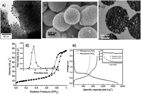 | ||
| Fig. 10 (a) TEM picture of SnO2 nanoparticles dispersed in the HTC matrix; (b) SEM micrograph of the resulting mesoporous SnO2 spheres after removal of the carbon matrix; (c) TEM micrograph of the same SnO2 spheres; (d) adsorption isotherm and pore size distribution of the resulting SnO2 spheres; (e) first discharge/charge profiles in lithium storage for the mesoporous SnO2 and microsized SnO2 samples cycled at a current density of 100 mA g−1. The inset shows the cycling performance of both samples cycled between voltage limits of 0.05 and 1 V. (Reproduced from ref. 33 with the permission of the American Chemical Society). | ||
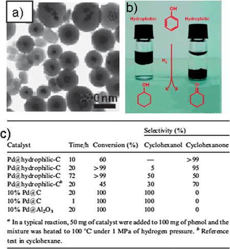 | ||
| Fig. 11 (a) TEM micrographs of Pd nanoparticles supported on hydrophilic carbon. (b) Potential mechanistic scheme explaining the selectivity of our catalyst towards cyclohexanone. (c) Catalytic activity of differently supported Pd for the hydrogenation of phenol. (Reproduced from ref. 34 with the permission of The Royal Society of Chemistry). | ||
Using this approach, Pd0 nanoparticles were prepared inside a carbon matrix, representing an environment with polar oxygenated hydrophilic groups on the channels towards the catalytic particles.34 This compound system proved to be a successful catalyst for the selective hydrogenation of phenol to cyclohexanone. The current solution synthesis of cyclohexanone is still necessarily a two step process which involves the reduction of phenol to cyclohexanol followed by further dehydrogenation to form cyclohexanone.35 The direct route preferred by industry can only be achieved in the vapor phase under rather harsh conditions.36 Compared with the commercial hydrophobic charcoal-supported catalyst, the more hydrophilic HTC catalyst showed good selectivity in water towards partial hydrogenation, generating mainly cyclohexanone. A possible mechanism is that the sorption properties of phenol and cyclohexanone onto hydrothermal coal are so different that the reaction site is simply depleted of the intermediate which then can be isolated (Fig. 11b). Such matrix effects operating with selective binding and enrichment are in our opinion a powerful option to bring technical catalytic systems closer to the performance of natural enzymes.
Another morphology of HC materials loaded with noble nanoparticles is the so-called “hybrid fleece” structure,37i.e. uniform carbonaceous nanofibers embedding noble-metal nanoparticles that show different average diameters and size distributions for different metals. These nanoparticles are loaded on the nanofibers via the spontaneous reduction of the noble-metal salts by the surface functional groups of as prepared carbonaceous nanofibers, such as reactive alcohol and aldehyde groups. Importantly, the resulting hybrid nanostructures performed as efficient catalysts for the 100% conversion of CO to CO2 at rather low temperatures.
The reasons for the good performance are multiple: fiber or fleece like supports are ideal for contacting gas reactions, and the high thermal, chemical, and mechanical stability contributes to the survival of nanostructures in an oxidative environment. Finally, the presence of binary carbon–metal contacts and the high specific metal surface area of the system must contribute too, as all reference experiments revealed no or only inferior reactivity.
The catalyst system is not restricted to being modified only by incorporating metal salts and precursors into the HTC process; water soluble organic monomers can also be successfully added and modify either the support or generate even metal-free catalytic activity. Thus, using hydrothermal carbonization of glucose in the presence of various organic monomers such as acrylic acid38 or vinyl imidazole,39 carbon materials were obtained with increased organic functionality. Here, the carbon precursor (carbohydrate) provides the scaffold with its thermal or mechanical stability to the system, while the organic monomer added in minor amounts brings in the functionality. Such a system is a chimera between a biomass-based, sustainable material and petrochemistry, however with the majority fraction based on sustainable resources.
For catalyst synthesis this organic modification is preferentially combined with the silica templating process reported in the previous section to generate high surface areas with beneficial pore connectivity. This combination leads to the production of a mesoporous carbon scaffold (Fig. 12a) with imidazole groups located on its surface. The presence of the functional groups was confirmed using elemental analysis, FT-IR and zeta potential measurements.
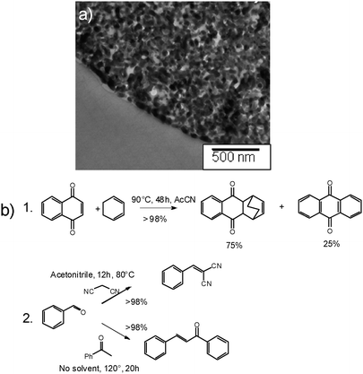 | ||
| Fig. 12 (a) TEM micrograph of the imidazole functionalized carbon replica described in the text. (b) Some reactions catalysed by this material: (1) the aromatisation of Diels–Alder condensates, and (2) Knoevenagel and aldol condensations. | ||
Imidazoles themselves are neither strongly basic nor strongly nucleophilic and thus have found only limited catalytic applications.40 In contrast, imidazolium ions (especially imidazolium based ionic liquids) have found numerous catalytic applications, either on their own41 or as stable carbenes.42 In order to test the availability of the imidazole grafted functions for catalysis, the material was alkylated by refluxing it overnight in toluene in presence of one mass equivalent of butyl bromide. The successful alkylation could be evidenced by EDX showing the presence of bromine in the solids (up to 1.5 atom%). The catalytic activity of this quaternary carbon material was tested with two reactions, which were recently reported to be promoted by imidazolium halides: (i) the aromatisation of unsaturated six-membered rings (especially Diels–Alder condensation products),43 and (ii) Knoevenagel and aldol condensations.44 The obtained results are summarised in Fig. 12b-1.
The Diels–Alder condensation of naphthoquinone and cyclohexadiene run in the presence of the metal-free carbon catalyst progresses to nearly complete conversion of the reactant, while anthraquinone (the re-aromatisation product) represented around 25 mol% of the products. Similarly, both the Knoevenagel condensation of benzaldehyde with malononitrile and the aldol condensation of benzaldehyde with acetophenone were achieved in high yields under relatively mild conditions (Fig. 12b-2) and with very good selectivity.
 | ||
| Fig. 13 SEM micrographs of hydrothermal carbon dispersions containing (a) 1 wt%, (b) 2 wt%, (c) 5 wt%, (d) 10 wt% of acrylic acid. (Reproduced from ref. 38 with the permission of the American Chemical Society). | ||
The presence of acrylic acid was confirmed with 13C-solid state NMR, and the amount of carboxylic groups increased as expected on increasing the amount of added acrylic acid. Furthermore, NMR made it possible to exclude a linear radical polymerization of acrylic acid since no polyacrylic acid moieties were found in the solution at the end of the reaction (liquid 1H-NMR) and suggested cycloaddition towards stable aromatic carboxylates instead. TGA experiments supported this view by actually reporting an increase in the thermal stability of the materials produced in the presence of acrylic acid.
These functional high surface area materials were tested as adsorbents for the removal of heavy metal ions from water. Ion binding capability goes highly non-linear with the content of acrylic acid. Pure HC carbons as well as the samples with only 1 wt% acrylic acid have, expectedly, the lowest binding capacity for both cadmium and lead. The capacity increases slightly for the 2 wt% sample (11.00 Cd(II) mg/g, 77.7 Pb(II) mg/g), while a dramatic increase in adsorption capacity is observed upon further increasing the amount of acrylic acid in the samples. This is to be related to the development of a pore system and accessibility of binding sites.
The 10 wt% acrylic acid containing carbon has the highest metal uptake capacity. The capacity of the 10AcA-C for lead ion is 351.4 mg/g (1.7 mmol/g) and for cadmium is 88.8 mg/g (0.79 mmol/g). In good agreement with other reports,45 Pb2+ ions are retained more strongly and in larger quantities than Cd2+ ions on all our carbon functional materials.
Comparing the absolute adsorption capacities with those of other adsorption studies46,47 it can be realized that values of 100–300 mg/g are indeed extraordinarily high and well beyond the capacities of standard synthetic ion exchange resins and other types of sorption materials. This underlines the potential of these functional hydrothermal carbon materials for ion binding and ion buffering purposes, also in environmental applications.
HC materials have been used and structurally improved as electrodes in Li ion batteries.10,48,49 However, the use of carbon colloids, prepared by the HTC process, as a fuel in order to increase the efficiency of the indirect carbon fuel cell has also been reported.50
2.3.4.1 Li ion batteries. Rechargeable lithium-ion batteries are essential to portable electronic devices. Owing to the rapid development of such equipment there is an increasing demand for lithium-ion batteries with high energy density and long lifetime.
For high energy density, the electrode materials in the lithium-ion batteries must possess high specific storage capacity and coulombic efficiency. Graphite and LiCoO2 are normally used as anode and cathode, respectively, and have high coulombic efficiencies (typically >90%) but rather low capacities (372 and 145 mAh g−1, respectively).51
The first application of HC as an anode in Li ion batteries was reported by Huang et al.10 After the hydrothermal carbonization of sugar, the resulting spherical particles were further carbonized under argon at 1000 °C for 5 h. The reversible lithium insertion/extraction capacity of this kind of material was about 400 mAh g−1. This proves that HC materials post-treated at higher temperatures have specific capacities in the same range as commercial graphite, which was a promising opening concerning the use of HC materials in Li ion batteries. Current values for carbon materials are, however, meanwhile around 800 mAh g−1, combined with excellent stability and dynamic rate behavior.52 However, other materials have been proposed in the last decade as anode materials, too. Among these, silicon has attracted great interest as a candidate to replace graphite owing to its numerous appealing features: it has the highest theoretical capacity (Li4.4Si ∼4200 mAh g−1) of all known materials, and is abundant, inexpensive, and safer than graphite.53 The practical use of Si powders as an anode in lithium-ion batteries is, however, still hindered by two major drawbacks: the low intrinsic electric conductivity and severe volume changes during Li insertion/extraction processes, leading to poor cycling performance.54
In order to overcome these problems, hybridization of both materials (C and Si) in one electrode material by HTC seemed to be a promising option.48,49 For that, pre-formed silicon nanoparticles were dispersed into a dilute solution of glucose followed by hydrothermal treatment at 180 °C. The carbon-coated particles were then further treated at 750 °C in order to improve the conductivity and structural order of the carbon layer. It was shown that the hydrothermal treatment, followed by high temperature carbonization, resulted in formation of a few nanometer thick layer of SiOx layer on the Si nanoparticles, effectively leading to a Si/SiOx/C nanocomposite. Some TEM micrographs of these materials are shown in Fig. 14a–d.
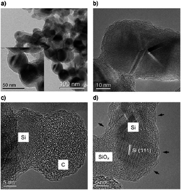 | ||
| Fig. 14 TEM images of the Si@SiOx/C nanocomposite nanoparticles produced by hydrothermal carbonization of glucose and Si and further carbonization at 750 °C under N2. (a) Overview of the Si@SiOx/C nanocomposites and a TEM image at higher magnification (in the inset) showing uniform spherical particles; (b) HRTEM image clearly showing the core/shell structure; (c), (d) HRTEM images displaying details of the silicon nanoparticles coated with SiOx and carbon. (Reproduced from ref. 48 with the permission of Wiley-VCH). | ||
It can be observed that the thickness of the layer forming a complete shell around the Si nanoparticles is around 10 nm (SiOx and C), whereas the diameter of the core is around 30–40 nm, which is very similar to the size of the primary Si nanoparticles. In HRTEM images (Fig. 14b–d) it becomes evident that the Si nanoparticles are coated with a layer of silicon oxide and a layer of carbon with varying thickness. Short, strongly bent graphene layers were observed on the surface of all of the particles (indicated by small arrows in Fig. 14d). HRTEM, Raman, and FTIR investigations confirm that the nanocomposite consists of a silicon core, a shell of thin amorphous SiOx, and a carbon layer. This structure turned out to be very interesting for lithium storage as it combines sufficient conductivity of graphene layers with polymer-like elasticity to withstand the deformation stresses throughout lithium insertion. The total amount of carbon in this sample was only 25%, according to elemental analysis and TGA.
The lithium-storage properties of these Si@SiOx/C nanocomposite electrodes were investigated in different electrolyte systems and compared to pure Si nanoparticles. Of all the analyzed systems, the Si@SiOx/C nanocomposite in conjunction with vinylene carbonate (VC) to form the solid/electrolyte interface showed the best lithium-storage performance in terms of highly reversible lithium-storage (1100 mAh g−1), excellent cycling performance, and high rate capability (Fig. 15).
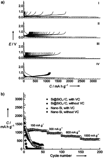 | ||
| Fig. 15 (a) Galvanostatic discharge/charge curves (Li insertion, voltage decreases; Li extraction, voltage increases, respectively) of pure Si nanoparticles (I, II) and Si@SiOx/C nanocomposite (III, IV) electrodes cycled at a current density of 150 mA g−1 between voltage limits of 0.05–1 V in VC-free (I, III) and VC-containing (II, IV) 1 M LiPF6 in EC/DMC solutions. (b) Cycling and rate performance of the same systems. (Reproduced from ref. 48 with the permission of Wiley). | ||
Applying higher amounts of carbohydrate in the same process, no thin carbon coating is formed, but the Si nanoparticles are incorporated into massive hydrothermal carbon spheres instead.49 The amount of silicon nanoparticles incorporated in this carbon matrix is about 15% according to TGA. As expected, the electrochemical performance of such materials is poorer than in the case of the coated Si nanoparticles. Nevertheless, this more simple C/Si nanocomposite shows highly stable reversible capacity (∼460 mAh g−1) at a high current rate of 300 mA g−1 in the voltage range of 0.05 to 1.2 V, which is still higher than the pure HC material, and has a better cyclability than the pure Si nanopowder.
Besides the combination of Si/C, there have been many other trials to improve the performance of Li ion battery electrode materials using the HTC process. For example, other authors produced NiO/C nanocomposite by dispersing the as-prepared net-structured NiO in glucose solution and performed subsequent carbonization under hydrothermal conditions at 180 °C.55 The carbon in the composite was amorphous by X-ray diffraction analysis, and its content was 15 wt% calculated according to energy dispersive X-ray spectroscopy (EDX). A transmission electron microscopy (TEM) image of the NiO/C nanocomposite showed that the NiO network was homogeneously filled by amorphous carbon. The reversible capacity of this NiO/C nanocomposite after 40 cycles is 429 mAh g−1, which is again much higher than that of NiO (178 mAh g−1). These improvements were again attributed to the carbon, which can enhance the conductivity of NiO, suppress the aggregation of active particles, and increase their structure stability during cycling.
Cao et al. produced HC/Sn nanocomposites by hydrothermal treatement of sucrose and SnCl4 solution.56After the carbon removal, the electrochemical properties of the hollow SnO2 materials were tested. This material has a high initial discharge capacity of 764 mAh g−1, close to its theoretical specific capacity, indicating a full utilization of all the SnO2 crystallites. The discharge capacity of this material remains 520 mAh g−1 after 20 cycles, indicating a good retention of capacity.
Although quite considerable progress has been made in improving the performance and lifetime of anode materials, a great deal of research is still dedicated to the improvement of the cathode in Li ion batteries. This task was addressed by hydrothermal carbon coating techniques. Thus, olivine LiMPO4 (M = Mn, Fe, and Co) cathodes with a thin carbon coating have been prepared by a rapid, one-pot, microwave-assisted hydrothermal process enabling a shortened reaction time (15 min) at 230 °C.57 Again, glucose was chosen as a source of hydrothermal carbon. The resulting LiMPO4/C nanocomposites were characterized by X-ray diffraction, Raman spectroscopy, scanning electron microscopy, and transmission electron microscopy (TEM) before and after heating at 700 °C for 1 h in an argon flow. The uniform nanocarbon coating enhanced the electronic conductivity and led to excellent electrochemical performance for LiFePO4/C in lithium cells. In contrast, both LiMnPO4/C and LiCoPO4/C exhibited in those experiments only inferior electrochemical performances even after carbon coating.
2.3.4.2 Carbon fuel cells. The idea for the electrochemical conversion of the potential energy of coal into electrical energy originates from the late 19th century, when W. Jacques introduced the principle of the noncombustive, electrochemical oxidation of carbonaceous matter in air.58 Carbon fuel cells are conceptually the most effective way of converting the chemical energy of carbon into electrical energy, especially compared to classical combustion processes. As the global reserves of coal exceed by far those of other fossil fuels, there have been numerous attempts in the past decades to develop and generally improve applicable carbon fuel cells,59,60 promising higher efficiency compared to conventional coal combustion.
Besides optimizing the fuel cell device, the efficiency of carbon fuel cells can also be optimized using carbon colloids as a fuel, as electrochemical oxidation of a solid certainly depends on the absolute surface area and its surface structure. Especially for the so called indirect carbon fuel cell, which operates in water at ambient temperatures, design of carbon colloid fuels seems to be a timely issue. Recently, a comparative study on classical carbon dusts and carbon dispersions prepared by the HTC process has been published.50 Different samples of lignite and anthracite were applied as reference materials, using a simple Fe3+-oxidation assay. The experiments revealed a significantly better capability of glucose derived hydrothermal coal for oxidation: it highly exceeds anthracite in its oxidation rate but also shows better oxidation properties than lignite. The reason for the lower oxidation rates of anthracite and pure graphitic carbon is presumably found in their dense, ordered structure of stable aromatic graphene sheets. For lignite the structure is more open and amorphous, thus making the carbon more accessible for oxidation. HTC coal is even more reactive, as it features a chemical structure mainly composed of aliphatic and olefinic building units, which are highly reductive and reactive, while the amount of conjugated aromatic rings is remarkably low. The micrometer-sized spherical particles dispersed in water additionally offer a more accessible surface for the heterogeneous oxidation process.
The HTC coal was then employed in an anodic half-cell coupled to a model VO2+/VO2+ cathode, making the procedure more suitable to be run on the laboratory scale than using the standard oxygen cathode. Fig. 16 displays the obtained results.
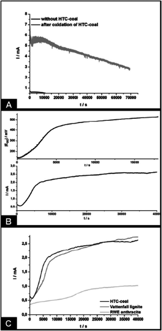 | ||
| Fig. 16 (A) Time dependent electric current generated from the oxidation of HTC coal in an indirect carbon fuel cell. Solutions of FeIII and VV were prepared in 0.5 mol L−1 H2SO4. Separation of half-cells was realized by a Nafion membrane while carbon felts were used as electrodes. (B) Development of open circuit potential Eoc (above) and current I (below) due to Fe2+ formation in the anodic half-cell via oxidation of HTC coal, indicating the reducing potential of bare HC dispersions. Charge equalization between the two half-cells was assured by a salt bridge containing a saturated KCl solution. Carbon felt was used as electrodes. (C) Comparison of hydrothermal and fossil carbon sources in the same set-up. (Reproduced from ref. 50 with the permission of the American Chemical Society). | ||
Such primary scientific experiments are of course far from any competitive technical device, but already prove that carbon colloids derived from hydrothermally treated biomass can indeed act as a potential fuel for decentralised energy generation with an overall zero-emission balance of CO2.
It is a brave thought, but given climate changes and the role of CO2 therein, it is in principle possible to develop a chemical “CO2 disposal” industry for sequestering the atmospheric CO2, even that from past industrialization. Biomass represents the biggest carbon converter with the highest efficiency to bind CO2 away from the atmosphere, and any type of carbonization can transfer this biomass into less degradable coal compounds.
Thus, using the HTC process to convert biomass into coal rapidly could represent a most efficient tool for CO2 sequestration.30 First, the desirable acceleration of the coalification of biomass by a factor of 106–109 makes it a technically attractive, realistic “artificial” instrument for fixing the carbon of biomass on a large scale. Secondly, it is the most efficient strategy for carbon fixation, with a “carbon efficiency” close to 1 (Fig. 17).
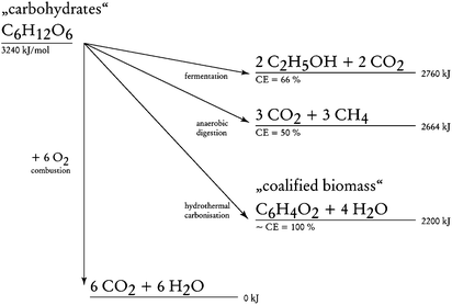 | ||
| Fig. 17 Comparison of different “renewable energy pathways” and carbon transfer schemes from carbohydrates. Here, preservation of combustion energy and the “carbon efficiency” of the transformation (CE) are compared. The “sum formula” of the coalified plant material is a schematic simplification. (Reproduced from ref. 30 with the permission of The Royal Society of Chemistry). | ||
Also, compared to the traditional high-temperature carbonization reactions, the HTC route proceeds under mild conditions at low temperature (≤200 °C), and the high exothermic characteristic (i.e. liberating about 10–30% of the combustion energy of the sugars) further promotes the reaction with ease. Another advantage of the HTC process is the fact that it takes place in water, therefore complicated and high cost schemes associated with biomass drying can be avoided. Therefore, the HTC process qualifies as an attractive technique to handle a significant part of the CO2 problem.
To effectively deal with the atmospheric CO2 problem, indeed large scale applications in the Gt/a range have to be started up. Adding hydrophilic carbons with high ion binding capacity and the ability to bind and keep water as some type of synthetic humus in order to improve soil quality is indeed one of those potential large scale applications. For “black soil”, it is indeed the carbon fraction which contributes significantly to the beneficial soil properties, either physically or chemically. Some experiments of mixing soil with hydrothermal carbon and studying its effect on plants’ growth are ongoing, and the preliminary results seem very promising.61
But also for purely technical processes such as CCS (carbon capture and storage), HC can offer sustainable low price materials for large scale applications. The success of CO2 capture with solid sorbents is dependent on the development of a low cost sorbent with high CO2 selectivity and adsorption capacity.62,63 In this direction, the nitrogen containing materials presented above show a lot of promise. Some preliminary CO2 adsorption experiments were performed on nitrogen enriched carbons and show very promising CO2 adsorption properties, both in terms of capacity and selectivity.64
Conclusions
We have reviewed the latest progress on hydrothermal carbonization (HTC), an alternative chemical pathway leading to a variety of carbonaceous materials. Although differences among the various materials (some cases require metal ions as catalyst while some others rely on a template to form specific shapes) are to be mentioned, significant common features do exist: HTC is in all its variations a green and sustainable alternative, as at least a majority of the precursors are biomass based, and the reaction takes place in pure water at mild temperatures without employing any hazardous surfactants or catalysts. Furthermore, the resulting materials are solid particles or high surface area scaffolds, while their surfaces are decorated with polar functional groups, thus making them hydrophilic and functional.Some considerations concerning the mechanism of this process starting from various carbohydrate precursors have been touched on, as well as the production of various pure carbonaceous materials in the presence of various templates. This was followed by extension towards the direct conversion of raw biomass into carbon materials. Then, various applications of such carbon materials in hot fields such as catalysis, adsorption and energy storage were presented, in some cases with properties far superior to those of the current gold standards of classical technology. This is worth underlining, as it is still the standard opinion that making processes more sustainable usually comes with a compromise. This is clearly not the case for functional carbon materials, which in our opinion is due to the fact that the more technological process of charring is replaced by a well defined chemical process in a solvent, namely very hot water.
Although the HTC process has proved to be extremely successful in the production of many different distinctive structures rich in a variety of functional groups, there are still many aspects to be studied and considered in the future.
Progress has already been made in understanding some of the mechanistic aspects regarding the carbohydrate transformation into such carbon rich deposits. The next step is to try to understand the mechanism of biomass transformation and the role of structure and chemistry directing side products, thus to find the optimal type of biomass and optimal conditions for the generation of large scale sustainable carbon material. Proteins, lipids, polyphenols and many other “comonomers” typically present in biomass will significantly contribute to the properties of the resulting carbonaceous co-condensates.
Then, porous carbons should be accessed using milder processes than the one of hard templating, presumably using inert bio-surfactants or other biomass based templates. A third big potential topic is further chemical conversions (such as hydrogenation) of the HC products, maybe opening pathways to a coal based polymer chemistry, again. New meaningful approaches with high potential impact are, however, in practice countless.
All these further studies will, however, facilitate the design of novel carbonaceous structures, interestingly mostly already very close to beneficial applications for our daily lives.
Acknowledgements
The authors are grateful to the EnerChem project and all the research partners involved in this project. M. A. thanks Shu-Hong Yu for a long cooperation on this subject. M. M. Titirici thanks Rezan Demir Cakan, Niki Baccile and Li Zhao for important contributions to the field.References
- A. Thess, R. Lee, P. Nikolaev, H. J. Dai, P. Petit, J. Robert, C. H. Xu, Y. H. Lee, S. G. Kim, A. G. Rinzler, D. T. Colbert, G. E. Scuseria, D. Tomanek, J. E. Fischer and R. E. Smalley, Science, 1996, 273, 483 CrossRef CAS.
- A. Eftekhari, P. Jafarkhani and F. Moztarzadeh, Carbon, 2006, 44, 1343 CrossRef CAS.
- L. Gherghel, C. Kubel, G. Lieser, H. J. Rader and K. Mullen, J. Am. Chem. Soc., 2002, 124, 13130 CrossRef CAS.
- F. Bergius, Die Anwendung hoher Drücke bei chemischen Vorgängen und eine Nachbildung des Entstehungsprozesses der Steinkohle, Knapp, Halle/Saale, 1913 Search PubMed.
- E. Berl and A. Schmidt, Justus Liebigs Ann. Chem., 1932, 493, 97 CrossRef CAS.
- J. P. Schuhmacher, F. J. Huntjens and D. W. van Krevelen, Fuel, 1960, 39, 223 CAS.
- M. W. Haenel, Fuel, 1992, 71, 1211 CrossRef CAS.
- M. M. Titirici, A. Thomas and M. Antonietti, Adv. Funct. Mater., 2007, 17, 1010 CrossRef CAS.
- X. J. Cui, M. Antonietti and S. H. Yu, Small, 2006, 2, 756 CrossRef CAS.
- Q. Wang, H. Li, L. Q. Chen and X. J. Huang, Carbon, 2001, 39, 2211 CrossRef CAS.
- M. M. Titirici, M. Antonietti and N. Baccile, Green Chem., 2008, 10, 1204 RSC.
- N. Baccile, G. Laurent, F. Babonneau, F. Fayon, M. M. Titirici and M. Antonietti, J. Phys. Chem. C, 2009, 113, 9644 CrossRef CAS.
- M. M. Titirici, A. Thomas and M. Antonietti, J. Mater. Chem., 2007, 17, 3412 RSC.
- H. S. Qian, S. H. Yu, L. B. Luo, J. Y. Gong, L. F. Fei and X. M. Liu, Chem. Mater., 2006, 18, 2102 CrossRef CAS.
- J. C. Yu, X. L. Hu, Q. Li, Z. Zheng and Y. M. Xu, Chem.–Eur. J., 2006, 12, 548 CrossRef.
- D. Eder and A. H. Windle, Adv. Mater., 2008, 20, 1787 CrossRef CAS.
- X. Sun and Y. Li, Angew. Chem., 2004, 116, 607 CrossRef.
- S. H. Yu, X. J. Cui, L. L. Li, K. Li, B. Yu, M. Antonietti and H. Cölfen, Adv. Mater., 2004, 16, 1636 CrossRef CAS.
- B. Deng, A. W. Xu, G. Y. Chen, R. Q. Song and L. P. Chen, J. Phys. Chem. B, 2006, 110, 11711 CrossRef CAS.
- J. Y. Gong, S. H. Yu, H. S. Qian, L. B. Luo and T. W. Li, J. Phys. Chem. C, 2007, 111, 2490 CrossRef CAS.
- Y. Wan, Y. L. Min and S. H. Yu, Langmuir, 2008, 24, 5024 CrossRef CAS.
- A. Arenillas, T. C. Drage, K. Smith and C. E. Snape, 16th International Symposium on Analytical and Applied Pyrolysis, Alicante, Spain, 2005, p. 298 Search PubMed.
- A. Vinu, S. Anandan, C. Anand, P. Srinivasu, K. Ariga and T. Mori, Microporous Mesoporous Mater., 2008, 109, 398 CrossRef CAS.
- A. P. Zeng, Y. B. Yin, M. Bilek and D. McKenzie, 2nd International Conference on Advances of Thin Films and Coating Technology, Singapore, 2004, p. 202 Search PubMed.
- H. Yoon, S. Ko and J. Jang, Chem. Commun., 2007, 1468 RSC.
- C. O. Ania, V. Khomenko, E. Raymundo-Pinero, J. B. Parra and F. Beguin, Adv. Funct. Mater., 2007, 17, 1828 CrossRef CAS.
- N. Baccile, M. Antonietti and M. M. Titirici, ChemSusChem Search PubMed , accepted.
- L. Zhao, N. Baccile, S. Gross, M. Antonietti and M. M. Titirici, Carbon, 2009 Search PubMed , in progress.
- M. M. Titirici, A. Thomas, S. H. Yu, J. O. Muller and M. Antonietti, Chem. Mater., 2007, 19, 4205 CrossRef CAS.
- M. M. Titirici, A. Thomas and M. Antonietti, New J. Chem., 2007, 31, 787 RSC.
- M. M. Titirici, M. Antonietti and A. Thomas, Chem. Mater., 2006, 18, 3808 CrossRef CAS.
- W. H. Shen, Y. F. Zhu, X. P. Dong, J. L. Gu and J. L. Shi, Chem. Lett., 2005, 34, 840 CrossRef CAS.
- R. Demir-Cakan, Y. S. Hu, M. Antonietti, J. Maier and M. M. Titirici, Chem. Mater., 2008, 20, 1227 CrossRef.
- P. Makowski, R. D. Cakan, M. Antonietti, F. Goettmann and M. M. Titirici, Chem. Commun., 2008, 999 RSC.
- N. Mahata and V. Vishwanathan, 1st Conference of the Indo-Pacific-Catalysis-Association, Cape Town, South Africa, 1998, p. 65 Search PubMed.
- S. Narayanan and K. Krishna, Appl. Catal., A, 2000, 198, 13 CrossRef CAS.
- H. S. Qian, M. Antonietti and S. H. Yu, Adv. Funct. Mater., 2007, 17, 637 CrossRef CAS.
- R. Demir-Cakan, N. Baccile, M. Antonietti and M. M. Titirici, Chem. Mater., 2009, 21, 484 CrossRef CAS.
- R. Demir-Cakan, P. Makowski, M. Antonietti, F. Goettmann and M. M. Titirici, Catal. Today, 2009 DOI:10.1016/j.cattod.2009.05.003 , in press.
- P. Makowski, J. Weber, A. Thomas and F. Goettmann, Catal. Commun., 2008, 10, 243 CrossRef CAS.
- H. Olivier-Bourbigou and L. Magna, J. Mol. Catal. A: Chem., 2002, 182–183, 419 CrossRef CAS.
- N. Marion, S. Diez-Gonzalez and I. P. Nolan, Angew. Chem., Int. Ed., 2007, 46, 2988 CrossRef CAS.
- H. Kaper, M. Antonietti and F. Goettmann, Tetrahedron Lett., 2008, 49, 4546 CrossRef CAS.
- P. Makowski and F. Goettmann, Adv. Synth. Catal., 2009 Search PubMed , submitted.
- D. Mohan, C. U. Pittman, M. Bricka, F. Smith, B. Yancey, J. Mohammad, P. H. Steele, M. F. Alexandre-Franco, V. Gomez-Serrano and H. Gong, J. Colloid Interface Sci., 2007, 310, 57 CrossRef CAS.
- Y. H. Li, J. Ding, Z. K. Luan, Z. C. Di, Y. F. Zhu, C. L. Xu, D. H. Wu and B. Q. Wei, Carbon, 2003, 41, 2787 CrossRef.
- Q. M. Yu, J. T. Matheickal, P. H. Yin and P. Kaewsarn, Water Res., 1999, 33, 1534 CrossRef CAS.
- Y. S. Hu, R. Demir-Cakan, M. M. Titirici, J. O. Müller, R. Schlögl, M. Antonietti and J. Maier, Angew. Chem., Int. Ed., 2008, 47, 1645 CrossRef CAS.
- R. Demir Cakan, M. M. Titirici, M. Antonietti, G. L. Cui, J. Maier and Y. S. Hu, Chem. Commun., 2008, 3759 RSC.
- J. P. Paraknowitsch, A. Thomas and M. Antonietti, Chem. Mater., 2009, 21, 1170 CrossRef CAS.
- A. M. Cao, J. S. Hu, H. P. Liang and L. J. Wan, Angew. Chem., Int. Ed., 2005, 44, 4391 CrossRef CAS.
- Y. S. Hu, P. Adelhelm, B. M. Smarsly, S. Hore, M. Antonietti and J. Maier, Adv. Funct. Mater., 2007, 17, 1873 CrossRef CAS.
- Y. D. Wang and J. R. Dahn, J. Electrochem. Soc., 2006, 153, A2188 CrossRef CAS.
- B. Gao, S. Sinha, L. Fleming and O. Zhou, Adv. Mater., 2001, 13, 816 CrossRef CAS.
- X. H. Huang, J. P. Tu, C. Q. Zhang and J. Y. Xiang, Electrochem. Commun., 2007, 9, 1180 CrossRef CAS.
- H. X. Yang, J. F. Qian, Z. X. Chen, X. P. Ai and Y. L. Cao, J. Phys. Chem. C, 2007, 111, 14067 CrossRef CAS.
- A. Vadivel Murugan, T. Muraliganth and A. Manthiram, J. Electrochem. Soc., 2009, 156, A79 CrossRef CAS.
- W. W. Jacques, Method of Converting Potential Energy of Carbon into Electrical Energy, US. Pat., US 555511, 1896 Search PubMed.
- W. H. A. Peelen, M. Olivry, S. F. Au, J. D. Fehribach and K. Hemmes, J. Appl. Electrochem., 2000, 30, 1389 CrossRef CAS.
- T. Horita, N. Sakai, T. Kawada, H. Yokokawa and M. Dokiya, J. Electrochem. Soc., 1995, 142, 2621 CrossRef CAS.
- M. C. Rillig and M. M. Titirici, 2009, manuscript in preparation.
- M. G. Plaza, C. Pevida, A. Arenillas, F. Rubiera and J. J. Pis, Fuel, 2007, 86, 2204 CrossRef CAS.
- M. B. Yue, L. B. Sun, Y. Cao, Z. J. Wang, Y. Wang, Q. Yu and J. H. Zhu, Microporous Mesoporous Mater., 2008, 114, 74 CrossRef CAS.
- Z. Bacsik, N. Hedin, M. M. Titirici and L. Zhao, 2009, in progress.
| This journal is © The Royal Society of Chemistry 2010 |