Quantitative determination of additives in a commercial electroplating nickel bath by spectrophotometry and multivariate analysis
Maider
Vidal
a,
José Manuel
Amigo
b,
Rasmus
Bro
b,
Miren
Ostra
a and
Carlos
Ubide.
*a
aDepartamento de Química Aplicada, Facultad de Química, Universidad del País Vasco, Apdo. 1072, 20080, San Sebastián, Spain. E-mail: carlos.ubide@ehu.es
bDepartment of Food Science, Quality and Technology, Faculty of Life Sciences, University of Copenhagen, Rolighedsvej 30, DK-1958, Frederiksberg C, Denmark
First published on 20th November 2009
Abstract
An electroplating nickel bath is usually composed of a number of organic additives to improve the plating process as well as to preserve its durability. Supreme Plus Brightener (SPB) and A-5(2X), used in a commercial electroplating nickel bath show highly overlapped UV-Vis spectra. These two additives are the only ones that present absorbance in the UV-Vis wavelength range. Therefore, a mixture of them can be resolved using multivariate calibration methods of UV-Vis measurements. In this work, Partial Least Squares (PLS) regression and Classical Least Squares (CLS) have been used to quantify both additives during the whole duration of an electroplating nickel bath. It was found that PLS regression provided the best results. To avoid negative influence of baseline drifts, first derivative spectra were used. Between 0.14 and 1.40 mL of the commercial product SPB per L of nickel bath can be determined with mean errors of about 6%. Between 4 and 24 mL of the commercial product A-5(2X) per L of nickel bath can be determined with mean errors of about 8%. The limits of detection (LOD) found for SPB and A-5(2X) were 0.11 mL L−1 and 3 mL L−1 respectively. The calibration models proved to be valid for at least eight months, including a change of spectrophotometer. The SPB concentration decays along the bath life according to a first order rate law, but A-5(2X) remains unchanged. Independent brightness measurements showed that it was intimately related to the SPB concentration, in such a way that any of them can be deduced from the other one. This is of prime importance to keep the bath conditions under control.
Introduction
Nickel electroplating baths are among those most frequently used for decorative, engineering and electroforming purposes. Additives in electroplating baths are responsible for the final quality of the coating. The additive control has been frequently accomplished in an empirical way, due to the lack of rapid and accurate analytical methods. Therefore, monitoring techniques are very useful in order to follow the behaviour of additives during the electroplating process. The highly complex chemical composition of baths, however, makes it difficult for control analysis and only a few references have been found dealing with additive monitoring.1,2A-5(2X) and Supreme Plus Brightener (SPB) are the commercial names of two organic additives for nickel electroplating baths They both show UV absorption bands. Nevertheless, their spectra are strongly overlapped, making it impossible to determinate their concentration in a simple manner.
The joint use of UV-Vis-NIR spectrophotometry and multivariate calibration algorithms has gained acceptance to resolve mixed signals3–6 and it can be an excellent alternative to the classical techniques that need previous separation procedures before determination.7 Multivariate calibration methods applied to spectral data are being increasingly used for biomedical and pharmaceutical analysis.8–10 They can use the whole spectra for the resolution of complex mixtures of analytes containing some interferences, for noise reduction, for outliers control etc.11 In this study, two very well-known multivariate models have been applied to UV data and compared: namely, Partial Least Squares (PLS) regression and Classical Least Squares (CLS).
PLS is a low-rank calibration method that discards irrelevant and unstable information contained in the data set (the X-matrix) and finds a linear combination between the X-matrix and the known concentration of the standards (the Y-matrix). Once the model has been established, it can be used to predict concentrations of sample mixtures. This variable reduction procedure affords improved prediction results,12 although sometimes PLS is a time-consuming method because it requires the building of a calibration model through standards, high enough in number and with known concentrations of additives.13 On the other hand, it is an accurate and robust method. It is especially appealing for analyte determination in complex matrixes with three or more components; moreover, it allows handle interferences whenever they are included and appropriately varying in some of the calibration set samples.
CLS is a simpler, faster and more rigid method. It does not need calibration standards since it only uses for calibration the pure spectra of absorbing species (analytes). As counterpart, the Lambert-Beer's law must be strictly obeyed. Complex matrixes may easily generate errors because of any kind of Beer's law deviation. Hence, it is not able to model hidden compounds or effects in the mixture (i.e. non-linearities or possible interferences).14
At first sight, interactions and non linearities are not expected in the case of the electroplating nickel baths. Consequently, the use of CLS looks attractive because of its simplicity; however, electroplating baths are complex matrices with several compounds at very high concentrations. This justifies the attempt of a softer algorithm such as PLS. The optimization process included signal pretreatment and variable selection in order to obtain the best results in the determination of additives concentration. The calibration model chosen proved to be robust enough to cope with changes occurring over time (eight months) including the change of the measuring instrument.
Experimental
Reagents
A volume of 1.8 L of a commercial nickel bath (Supreme Plus, Atotech formulation) was used with the following composition: NiSO4·6H2O (250 g L−1), NiCl2·6H2O (50 g L−1) and H3BO3 (45 g L−1) as non-additive solution; and SA-1 (2.6 ml L−1), A-5(2X) (20 ml L−1), NPA (2 ml L−1) and Supreme Plus Brightner (SPB) (1 ml L−1) as additives (additives from Atotech, Berlin, Germany). The chemical composition of additive solution is unknown. The final pH was 4.0 and it was maintained constantantly along the process with addition of either NiCO3 or H2SO4 as required. Non-additive chemicals were of analytical reagent grade (Panreac or Fluka) and used without further purification. Additives were obtained from Atotech (Berlin, Germany) and used as received. Doubly distilled water was used throughout.Apparatus
The following instrumentation was used (Fig. 1): an electrodeposition vessel with a water jacket (Afora, Barcelona, Spain) for the nickel bath (65 °C); a Crison 501 pH meter (Alella, Spain); a Haake water bath thermostat controlled by an external probe dipped into the nickel bath; a rectifier (±20A/30V) from HQ Power (Nedis BV, The Netherlands) (model no. PS 3020) for electrodeposition, a diode-array spectrophotometer Hewlett Packard (Avondale, PA, USA) 8452A (during the work, an Agilent 8453 spectrophotometer (Santa Clara, CA, USA) was also used instead) and a Novo-Gloss Lite™ glossmeter (Eibar, Spain). A sequential injection (SI) set-up was also used to take the solution from the bath to the spectrophotometer and back to the bath; it included a multiburette 4S and a port selection valve VA + 1 from Crison (Alella, Spain). Micropipettes Brand (Wertheim, Germany) or Eppendorf (Hamburg, Germany) were used throughout.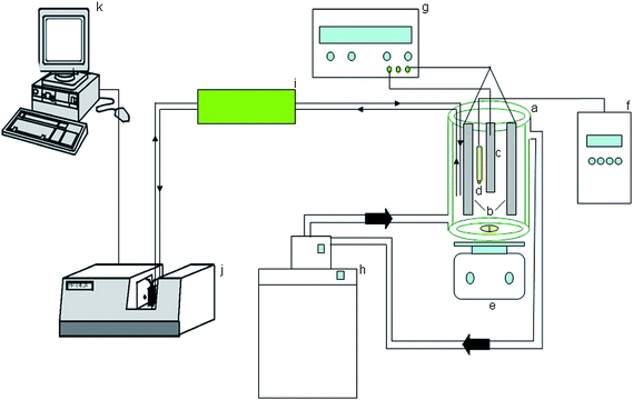 | ||
| Fig. 1 Manifold for process analysis of nickel electroplating. a, vessel for electrodeposition; b, anodes; c, cathode; d, pH double electrode; e, magnetic stirrer; f, pH-meter; g, current source; h, water bath thermostat; i, pumping-SI system; j, spectrophotometer; k, computer. | ||
Software and data processing
Experimental data was acquired with a computer coupled to the spectrophotometer. The SI system was controlled with a commercial programme (AutoAnalysis, Sciware, Mallorca, Spain). Absorbance spectra were treated with the UNSCRAMBLER v. 9.7 (Camo A S−1, Trondheim, Norway, 2007) software package which allowed the application of PLS; Matlab 7.4.0 software (The Mathworks Inc., Natick, USA) with PLS_Toolbox (Eigenvector Research Inc, USA) was also used for CLS. The Savitzky–Golay derivative transformation, with a three-point filter width and polynomial order two was used when necessary for background and base-line correction.15 The fundamentals of PLS have been given elsewhere16,17 and new points of view are frequently given.13,18 To test the prediction capability of the developed models, the statistic relative error (RE) was used: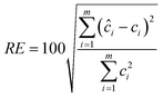 | (1) |
Nickel electrodeposition
Nickel electrodeposits were obtained galvanostatically in a glass cylindrical vessel (10.5 cm inner diameter, 21 cm height) of approximately 2 L of capacity (Fig. 1) with a lid that minimized heat and solvent losses. The electrodeposition was carried out on both sides of 16.5 × 3 cm commercial steel sheets at a temperature of 65 °C with mechanic stirring under 4 A dm−2 current density for 15 min. Prior to each electrodeposition, the steel sample was cleaned with soap and water, then with calcium carbonate, and finally etched with hydrochloric acid/Beizentfetter solution for 30 s and rinsed with water. Two 20 × 3 cm Ni pieces were used as anodes. An amount of 53 steel sheets were nickel plated along the bath life. After that, the bath was considered to have run out.Procedures
Spectrophotometric measurements were carried out in an automatic way by a SI system (Fig. 1). The strength of a SI system lies on the ability to perform highly reproducible and automated sample manipulations (sample clean-up, chemical reactions prior to spectrum acquisition etc.),20 and it has been successfully applied in the simultaneous determination of analytes with a diode-array spectrophotometric detector.21 The SI-system was configured to extract 25 μl of sample from the bath and then it was diluted approximately 70 times with distilled water and taken to a detector with a very high precision. The first measurement carried out daily with the SI system was always removed because it was unstable. The spectra were acquired between 248 and 320 nm every 2 nm.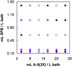 | ||
| Fig. 2 Concentration matrix for SPB and A-5(2X) mixtures. Circles, calibration; squares, validation. Filled marks are replicates. | ||
To make a study on accuracy and precision, five bath samples at several fixed Supreme Plus Brightener and A-5(2X) concentration levels were randomly measured five times.
Results and discussion
Additives A-5(2X) and SPB show absorbance in the UV region where no other bath component shows UV signal; that is, there is not interference from other materials in the bath as it can be deduced from Fig. 3. The spectra of both additives are completely overlapped. | ||
| Fig. 3 UV spectra of (1) Supreme Plus Brightener (SPB) and (2) A-5(2X), (3) Nickel bath. The conditions of both additive solutions were the same as the nickel bath (see Experimental, Reagents), with the exception of the other additive that was absent. | ||
Data pretreatment and variable selection
The variability of the collected spectra due to the use of different measuring apparatus or to the time passage is a problem to deal with. In this case, an amount of 64 standard samples with the same bath composition of non-additive components, SA-1 and NPA, but different concentration of A-5(2X) and SPB were prepared and their UV spectra were measured. The first few measurements were carried out with a Hewlett Packard 8452A spectrophotometer, but due to an equipment renewal, the spectrophotometer was changed to an Agilent 8453A. Furthermore, measurements of standards were performed along an eight-month period and all of these measurements were kept and used. This allowed the building of a more robust calibration model, able to cope with unforeseen variations in the bath samples.In Fig. 4a some standard spectra are depicted. An instrumental drift can be appreciated between data acquired with spectrophotometer Hewlett Packard 8452A (—) and those obtained with the spectrophotometer Agilent 8453 regardless of whether early data (· — ·) or late data (·•·) are considered. A slight drift can also be appreciated between early and late data (Fig. 4a, zoomed top-right box). These differences, however, can be minimized through both a spectral pretreatment and a variable selection. Common spectral pretreatments include Standard Normal Variate method (SNV),22 Multiplicative Scatter Correction method (MSC)23 or the use of derivative signals.24 For instance, SNV and MSC have been successfully applied in Raman or infrared spectroscopy;25,26 calibration models based on derivative spectral data are used to reduce scatter effects. A first derivative removes an additive baseline and a second derivative removes a linear baseline.24 These methods have successfully been applied to the multicomponent analysis of mixtures by UV-Vis spectrophotometry.27 In this work, first-derivative with a Savitzky-Golay approach (three-point filter width and polynomial order two) was used. The choice of the window size is a trade-off between noise reduction and distortion of the spectrum; window sizes of five- or seven-point filter are generally used,28 but in this case a three-point filter was used because a larger window size resulted in higher errors, probably due to spectrum distortion. This pretreatment minimized both the instrumental and time drifts (Fig. 4 b, zoomed bottom-left box). An enlarged view of drifts in spectra can be seen when residuals of CLS models are plotted vs. wavelength. CLS residuals represent the difference between the recovered spectra of standards and those of the pure species.29 The higher the residuals are, the larger the difference between the pure spectra and the standard spectra. In our measured spectra, residuals are very high for long wavelengths when raw data are used (Fig. 4c), but they are negligible for first derivative spectra (Fig. 4d).
 | ||
| Fig. 4 (a) Raw data. (b) First derivative data. (c) Residuals of CLS model using raw data. (d) Residuals of CLS model using first derivative data. (—) Data acquired with Hewlett Packard 8452A. (·—·). Data acquired with Agilent 8453 (early measurements). (·•·) Data acquired with Agilent 8453 (late measurements). | ||
Variable selection can sometimes be useful for improving multivariate calibration models by removing variables that do not contain useful information.30,31 In this case, different ranges were tested and the region 256–296 nm was confirmed to give the best results, as it could be expected from Fig. 3. Therefore, this region was used for building the calibration models. In any case, both raw and first derivative data were always used to make PLS and CLS calibration models and results were compared.
A model with only 12 samples for the calibration set, all of them measured with the same spectrophotometer, HP8453, was also tested as calibration set, but poor results were obtained and so the model was not included.
Calibration models
Table 1 summarizes the results obtained for the calibration of mixtures of SPB and A-5(2X) additives in nickel electroplating bath matrices. The Figures of merit obtained for the models are included. The limit of detection (LOD) was deduced from predicted vs. reference value plots.32 In this method, the concentration values found for standards, after applying the proposed calibration model, are represented versus the reference values and the plot is used as a calibration line to find the detection limit (LOD) through the 3s approach. The value of s is the one obtained from the regression line (sy/x).33The number of LVs ranged between 3 and 5, which shows that there are sources of variance different from the concentration of analytes (additives). Some part of the extra variance might come from the drift of spectra along time and from the change of instrument (Fig. 4). This is the reason why when first derivative data is used, the number of LVs is lower (Table 1). There is still some extra unexplained variance that PLS was able to model using an additional LV. On the contrary, CLS had some difficulties to accomplish it. The consequence is that mean errors with PLS always keep under 10% (Table 1), regardless if raw or first derivative data is used. Similar errors are obtained for both additives, even though SPB contribution to the experimental signal is very low (Fig. 3). On the contrary, mean errors obtained with CLS are much higher (between 9.2 and 23%) showing that CLS always provides poor results. This is probably due to the presence of a complex matrix. The CLS model for SPB (the lower signal contribution) is much worse (15–23% mean errors) than the CLS model for A-5(2X) (the higher signal contribution, 9–12% mean errors). The lower random errors obtained for SPB using PLS gave lower detection limit compared to those obtained with CLS. In the case of A-5(2X), errors are not so different for both algorithms and consequently they are the limits of detection.
Accuracy and precision
Table 1 shows the mean precision for SPB and A-5(2X) in the whole range of concentrations shown in Fig. 2. Different and independent empirical estimation could be obtained for each additive using several replicates at fixed concentration levels. The concentration ratio range: A-5(2X)/SPB was set between 2.8 and 60. These measurements were considered as an external test set and were collected several months after the measurement of the main part of the calibration samples. Results are given in Table 2. Some slight systematic errors (just above 10%) were found for SPB and A-5(2X) when the PLS model was used. CLS models, however, gave higher systematic errors for low A-5(2X) concentrations (up to 40%). Precision was better than 5% in 90% of individual cases for A-5(2X) and 60% for SPB. Nonetheless, low concentrations of SPB were determined with less precision (11–16%) when PLS and raw data were used. In general, PLS provides better results than CLS and the use of first derivative data always furnishes similar or slightly better (but not much) errors than raw data. If there is only a need for checking the evolution of the additive at the first stage of the bath life, when the quality could be still considered acceptable, not very fine results are needed and CLS could well be used, otherwise, PLS is strictly necessary to obtain fine results.| Algorithm | Experimental data | SPB | A-5(2X) | ||||||
|---|---|---|---|---|---|---|---|---|---|
| Added | Found | Error(%) | RSD(%) | Added | Found | Error(%) | RSD(%) | ||
| PLS | raw | 0.14 | 0.12 | −14 | 13 | 4.0 | 3.9 | −2.5 | 2.2 |
| 0.15 | 7 | 11 | 24 | 26 | 8 | 3.8 | |||
| 0.20 | 0.19 | −7 | 16 | 12 | 13 | 8 | 8.3 | ||
| 1.40 | 1.59 | 14 | 1.3 | 4.0 | 4.4 | 10 | 3.4 | ||
| 1.55 | 11 | 1.4 | 24 | 27 | 12 | 0.8 | |||
| 1st derivative | 0.14 | 0.13 | −7 | 9.8 | 4.0 | 4.3 | 7.5 | 2.0 | |
| 0.13 | −7 | 5.0 | 24 | 27 | 12 | 5.0 | |||
| 0.20 | 0.20 | 14 | 12 | 14 | 17 | 5.0 | |||
| 1.40 | 1.55 | 11 | 2.0 | 4.0 | 3.9 | −2.5 | 2.8 | ||
| 1.46 | 4.5 | 1.6 | 24 | 26 | 8 | 1.0 | |||
| CLS | raw | 1.40 | 1.21 | −13 | 1.6 | 4.0 | 5.6 | 40 | 1.6 |
| 1.47 | 5.0 | 1.2 | 24 | 26 | 8 | 1.2 | |||
| 1st derivative | 0.2 | 0.2 | 11 | 12 | 13 | 9 | 5.4 | ||
| 1.40 | 1.34 | −4.1 | 1.8 | 4.0 | 4.8 | 20 | 1.3 | ||
| 1.30 | −7.5 | 1.7 | 24 | 26 | 8 | 1.1 | |||
Additive determination in a commercial electroplating nickel bath
An electroplating nickel bath was prepared according to a commercial formulation and used to plate steel sheets in the way explained in the experimental section. The concentrations of SPB and A-5(2X) could be monitored over the time by an on-line interfacing that automatically sampled one aliquot and measured the UV spectrum. The results obtained for SPB and A-5(2X) along the bath life, after using PLS and CLS models previously developed (Table 1), can be seen in Fig. 5. Concentrations found under LOD values given in Table 1 are represented by open marks and are included with informative purposes exclusively. The lower LOD values corresponding to PLS method can clearly be seen for SPB additive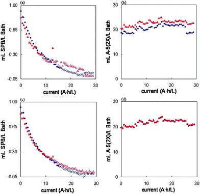 | ||
| Fig. 5 SPB ((a) and (c)) and A-5(2X) ((b) and (d)) concentrations in the bath along the electrodeposition process. (a) and (b) raw data; (c) and (d), first derivative data. Wavelengths from 256 to 296 in every case. (Rhombs, PLS; triangles, CLS. Open marks, values under the detection limits given in Table 1). | ||
Results obtained with both algorithms, PLS and CLS, were not much different. Moreover, it made little difference whether raw (Fig. 5a and 5b) or first derivative data (Fig. 5c and 5d) was used. However, when pretreatment was made, differences were still smaller. The higher precision of PLS can be appreciated in Fig. 5a and 5c, where smoother concentration curves were obtained. The lower limit of detection with PLS is also appreciated. All this, as well as the lower RE(%) values found for calibration and validation, made the PLS models with first derivative data the most suitable for both additives, because more precise predictions with lower errors were obtained.
The concentration of A-5(2X) does not change appreciably along the bath life but the concentration of SPB decreases as electroplating proceeds. This decay follows a first order law as it can be seen in Fig. 6, where the logarithmic plot is straight for at least three half-lives. The pseudo-first order constant obtained from the slope of the logarithmic plot can be used to evaluate the rate of consumption of SPB additive. In this case, the value of the rate constant, when PLS and first derivate data was used, was 0.137 ± 0.005 (A h L−1)−1. The decomposition products of SPB do not show UV-vis absorption and they were not identified by any other experimental technique; in any case, the composition of the additive is unknown and neither do we have any hypothesis about the decomposition reaction path, nor have we found in the literature any related references. However, literature is abundant in references on decomposition of saccharin7,34 (probably the main component of A-5(2X) additive), but it keeps stable along time in the present case (Fig. 5b and 5d). On the other hand, no explicit information has been found on decomposition of the other additives (SA-1 and NPA) and because they do not show UV-vis absorption, they were not studied further.
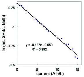 | ||
| Fig. 6 First order kinetic plot for SPB decay in the electroplating bath when PLS model is applied to first derivative data. | ||
The quality of plating decreased significantly in terms of brightness along the bath life. To follow this decay, a glossmeter was used and brightness was measured in the steel sheets after plating. Measurements were taken in the middle of both sides and the mean value was used. Measurements were taken at a 60° angle and the values are depicted in Fig. 7 together with the concentration of SPB in the bath at that moment. Both decays follow a similar pattern. A high correlation between both sets of data was obtained (r = 0.97), pointing to a direct relationship between the SPB concentration in the bath and the brightness obtained for the steel sheets. It means that the brightness obtained can be deduced in advance when the SPB concentration in the bath is known and vice versa. Consequently, the amount of SPB that should be added to the bath to obtain satisfactory brightness results can be known beforehand, taking measurements with the glossmeter on the last steel sheet.
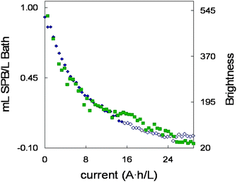 | ||
| Fig. 7 SPB concentrations ◆ and brightness evolution ■ along the bath life. Open marks (◇) represent SPB concentrations lower than the limit of detection (LOD) of PLS model. | ||
Conclusions
UV-Vis spectrophotometry has proven to be a suitable technique to follow the evolution of A-5(2X) and SPB additive concentrations in a nickel bath. Multivariate methods of calibration have been applied because of the spectral overlapping. Both PLS and CLS models can be used for monitoring the additive degradation along the life of the bath, but best prediction results are obtained by using PLS with first derivative experimental data. The level of SPB in the bath follows a first-order decay model and can be used to estimate the quality of the deposit in terms of brightness. The proposed method can be considered a process analysis that can be implemented at a close-to-real time. This can allow you to keep constant the additive (SPB) concentration and, consequently, the bath performance.Acknowledgements
The authors acknowledge financial support from MICINN (Project CTQ2008-06751-C02-02/BQU) and UPV/EHU (Project GIU07/58). MV acknowledges financial support from GV in the form of a scholar fellowship. CIDETEC (Centro de Tecnologías Electroquímicas) (San Sebastian, Spain) and Atotech S.A. (Erandio, Vizcaya) are also acknowledged for providing the bath additives.References
- C. Z. Gao, R. T. Liu, R. D. Pan and Y. Zheng, Transactions of the Institute of Metal Finishing, 2006, 84, 5 Search PubMed.
- M. Blanco, J. Coello, H. Iturriaga, S. Maspoch and D. Serrano, Fresenius J. Anal. Chem., 1999, 363, 364–368 CrossRef CAS.
- M. Blanco, J. Coello, F. González, H. Iturriaga and S. Maspoch, J. Pharm. Sci., 1993, 82, 834–837 CrossRef CAS.
- A. Barriola, E. García, M. Ostra and C. Ubide, J. Electrochem. Soc., 2008, 155, D480–D484 CrossRef CAS.
- M. Ulmscheneider; and Y. Roggo In Pharmaceutial Manufacturing Handbook; Gad, S. C., Ed.; John Wiley & Sons, Hoboken, NJ, 2008, 353–410 Search PubMed.
- S. Wold, GIT Lab. J., Eur., 2007, 11(1–2), 22–25 Search PubMed.
- D. Mockute and G. Bernotiene, Surf. Coat. Technol., 2000, 135, 42–47 CrossRef CAS.
- J. M. Amigo, A. Surribas, J. Coello, J. L. Montesinos, S. Maspoch and F. Valero, Chemom. Intell. Lab. Syst., 2008, 92, 44–52 CrossRef CAS.
- C. Ravn, E. Skibsted and R. Bro, J. Pharm. Biomed. Anal., 2008, 48, 554–561 CrossRef CAS.
- I. Durán Merás, A. Espinosa Mansilla, F. Salinas López and M. J. Rodríguez Gómez, Anal. Bioanal. Chem., 2002, 373, 251–258 CrossRef CAS.
- R. Bro, Anal. Chim. Acta, 2003, 500, 185–194 CrossRef CAS.
- K. H. Esbensen, Multivariate Data Analysis – in practice, Camo, Oslo, 5th ed., 2006, 137–139 Search PubMed.
- H. Martens and M. Martens. Multivariate Analysis of Quality. An introduction, Wiley, Chichester, 2001, 111–125 Search PubMed.
- B. G. M. Vandeginste, D. L. Massart, L. M. C. Buydens, S. De Jong, P. J. Lewi and J. Smeyers-Verbeke, Handbook of Chemometrics and Qualimetrics: Part B, Data Handling in Science and Technology 20B, Elsevier Science B.V., Amsterdam, 1998, 353–356 Search PubMed.
- A. Savitzky and M. J. E. Golay, Anal. Chem., 1964, 36, 1627–1639 CrossRef CAS.
- N. Martens and T. Næs, Multivariate Calibration, Wiley, Chichester, 1989, 116 Search PubMed.
- P. Geladi and B. R. Kowalski, Anal. Chim. Acta, 1986, 185, 1 CrossRef CAS.
- R. G. Brereton, Chemometrics. Data Analysis for the Laboratory and Chemical Plant, Wiley, Chichester, 2003, p. 297 Search PubMed.
- D. M. Haaland and E. V. Thomas, Anal. Chem., 1988, 60, 1193 CrossRef CAS.
- B. Lendl, R. Schindler and R. Kellner, AIP Conference Proceedings, 1998, 430 (Fourier Transform Spectroscopy), 403–406 Search PubMed.
- A. Pasamontes and P. Callao, Chemom. Intell. Lab. Syst., 2006, 83, 127–132 CrossRef CAS.
- T. Naes, T. Isaksson, T. Fearn and T. Davies. Multivariate Calibration and Classification, NIR Publications, Chichester, 2002, 124–125 Search PubMed.
- T. Næs, T. Isaksson, T. Fearn and T. Davies. Multivariate Calibration and Classification, NIR Publications, Chichester, 2002, 114–119 Search PubMed.
- T. Næs, T. Isaksson, T. Fearn and T. Davies. Multivariate Calibration and Classification, NIR Publications, Chichester, 2002, 107–114 Search PubMed.
- N. Chieng, S. Rehder, D. Saville, T. Rades and J. Aaltonen, J. Pharm. Biomed. Anal., 2009, 49, 18–25 CrossRef CAS.
- J. Moros, I. Llorca, M. L. Cervera, A. Pastor, S. Garrigues and M. de la Guardia, Anal. Chim. Acta, 2008, 613, 196–206 CrossRef CAS.
- C. Bosch Ojeda, F. Sanchez Rojas and J. M. Cano Pavon, Talanta, 1995, 42, 1195–1214 CrossRef.
- T. Næs, T. Isaksson, T. Fearn and T. Davies. Multivariate Calibration and Classification, NIR Publications, Chichester, 2002, 112 Search PubMed.
- H. Li, F. R. Van de Voort, A. A. Ismail, J. Sedman, R. Cox, C. Simard and H. Buijs, Journal of American oil Chemists' Society, 2000, 77, 30–35 Search PubMed.
- G. M. Hadad, A. El-Gindy and W. M. M. Mahmoud, Spectrochim. Acta, Part A, 2008, 70, 655–663 CrossRef.
- M. Shamsipur, R. Ghavami, H. Sharghi and B. Hemmateenejad, Ann. Chim., 2005, 95, 63 CrossRef CAS.
- M. C. Ortiz, L. A. Sarabia, A. Herrero, M. S. Sánchez, M. B. Sanz, M. E. Rueda, D. Giménez and M. E. Meléndez, Chemom. Intell. Lab. Syst., 2003, 69, 21 CrossRef CAS.
- J. N. Miller and J. C. Miller, Statistics and Chemometrics for Analytical Chemistry, 5th ed., Pearson Education, Harlow, 2005, 115–116 Search PubMed.
- J. W. Dini, Electrodeposition. The Materials Sciente of Coatings and Substrates, Noyes Publications, Park Ridge, 1993, 215–216 Search PubMed.
| This journal is © The Royal Society of Chemistry 2010 |