An illustration of the physical robustness of silica monolithic rod columns
Paul Geoffrey
Stevenson
and
Ross Andrew
Shalliker
*
Australian Centre for Research On Separation Science (ACROSS) and Nanoscale Organisation and Dynamics Group, University of Western Sydney, Parramatta, Australia. E-mail: r.shalliker@uws.edu.au; Fax: +61 2 96859951; Tel: +61 2 96859915
First published on 5th November 2009
Abstract
A commercial silica monolithic rod column (100 × 4.6 mm) was cut into smaller sections using a saw. Each time a section was cut from the column, the performance of the remaining intact monolith was retested. No significant change in the performance of the bed was recorded following the removal of 40 mm of the column in three separate cut sections. The work illustrates that monoliths are extremely robust and that they can be remodelled to different lengths if required, or a blocked section of the column (i.e. inlet) could be removed in much the same manner as for GC columns.
Analytical scale silica monoliths, referred to as monolithic rods, are made using a sol–gel process.1,2 The rod is a continuous porous silica matrix, with a bimodal pore size distribution. Large through pores allow for bulk mobile phase transport, while a mesoporous distribution allows for solute retention, increased surface area and pore volume. The higher bed permeability of the monolith, compared to particle packed columns, allows these columns to be operated at higher flow rates than particle packed columns, and because the C-term on the monolith is lower than particle packed columns, there is a smaller decrease in efficiency at these higher mobile phase velocities. Monoliths and their application in HPLC have been comprehensively reviewed.3
Because the monolithic bed is made as a porous solid, there is no need to retain particles in the tube in the same manner as is required for particle packed columns. Hence frits are not incorporated into the design, in either the inlet or outlet fittings. This can cause a problem if samples contain particulate material or are only sparingly soluble in the mobile phase, as these particulates then impact directly on the head of the monolith, rather than the retaining frit. The retaining frit of a particle packed column can be carefully replaced, but particulate build up on the head on the monolith is more difficult to remove, usually requiring backflushing, which may or may not be successful. The solution is to use a guard column, but not all chromatographers like to employ the services of a guard column since the separation process may not be the same as the analytical column.
The monolithic column shows great promise in the application of two-dimensional HPLC (2D HPLC), especially in the second dimension when comprehensive analysis of the sample is undertaken.4 In comprehensive analysis, the second dimension must be fast so that the wrap-around effect or back mixing does not occur.4 That is, sample transported to the second dimension elutes in the order corresponding to the order in which it was transported. Quickly eluting species from the second cut, for example, should not elute prior to the strongly retained species transported from the first cut. If this occurs, chaos is introduced into the separation. Hence, to avoid this chaotic band displacement, the second dimension must be completed before the next fraction is transported from the first dimension. Therefore, in order to maximise the efficiency in the operation of the 2D HPLC separation, especially if the separation is nearing its limits in operation, there must be optimisation of the flow differential between the first and second dimension. This means the first dimension runs at low flow rates, the second at high flow rates. In order to minimise this flow differential, and allow the first dimension to run as fast as possible in order to minimise the total analysis time, optimisation of the separation conditions in the second dimension is important. Essentially there are four aspects in the second dimension that can be optimised to improve speed; (1) adjust retention factors by changing the solvent composition, (2) optimise flow velocity, (3) employ higher column temperatures to minimise solvent viscosity and (4) adjust the column length. For a given separation, the solvent compositions are often fixed in order to maintain resolution and gradient elution is often employed. The flow velocity is usually set to the pressure limits of operation, but consideration must also account for the efficiency that is obtained at that flow rate, so that separation is maintained. Column temperature is a variable that is underutilised but receiving recent interest, and is showing promise as a variable since viscosity decreases as temperature increases.5 This allows higher flow rates to be employed. The column length is fixed by commercial availability, and for silica based monolithic columns available formats are 100 × 4.6 mm, 50 × 4.6 mm and 25 × 4.6 mm. If longer columns are required, then they can be coupled, but generally the shorter columns suffice as the second dimension sacrifices theoretical plates for speed.
This brings us to the point of the current study, which is, what if the ideal column length of the monolith in the second dimension is intermediate between 100 and 50 mm? If this were the case with particle packed columns, the solution is simple; prepare a column of the required length to yield separation efficiency and speed to suit the requirements of the second dimension. But if monoliths are to be employed, the solution is less simple since silica based monoliths are difficult to prepare and hence use is largely restricted to commercial products. Having said that, the monolith is a porous solid and rigid and capable of being cut to new configurations.
In this work for example we prepared three monoliths, each derived from the same 100 × 4.6 mm i.d. C18 silica monolith (encased in PEEK – Onyx (Phenomenex, Australia). Three successive monoliths were prepared by cutting a known length (12 mm) from the outlet section of the original commercial monolith. The end fitting was then reattached and the column retested. This was repeated twice more, each time removing a known length of tubing from the outlet (∼10 mm) and then refitting the outlet fitting and retesting.
Specifically, the procedure for engineering new length monoliths from the commercial 100 mm columns is detailed below:
Step 1: Use a sharp saw, in this case a saw designed for picture framing with 15 teeth per inch, make a cut at the column outlet, perpendicular to the wall, all the way through the monolith. Care should be exercised to avoid burring.
Step 2. Using a grinder, bevel the cut edge at ∼45°.
Step 3. Flush the column with mobile phase to remove dust.
Step 4. Rethread the outlet section of the column tube so that the outlet fitting can be reattached. In this case, an 8 mm M8 × 0.75 die was employed. Care should be exercised during this step because, if this is not carried out carefully, the head fitting will not sit tight on the outlet and result in a void in the outlet. Reflush column to remove dust.
Step 5. Apply the head fitting, tighten and check for leaks.
The photographs in Fig. 1, for example display pictorially this process.
 | ||
| Fig. 1 Photographs illustrating the process of cutting and rethreading the monolith column. | ||
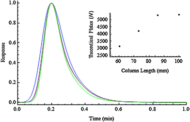
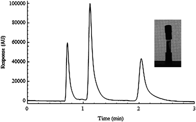
Each of the columns were tested using a three component mixture consisting of thiourea, toluene and butyl benzene. Separation was undertaken using a mobile phase of methanol–water (80/20) at a linear velocity of 0.10 cm s−1. Fig. 2 (curve a) shows the chromatogram that was obtained on the original (unmodified) monolith. The chromatograms in Fig. 2(b, c and d) illustrate the separations that were obtained on columns that were cut to lengths of 85.8, 73.3 and 60.5 mm, respectively. In each case, the peak shapes were virtually unaffected by the process employed to shorten the bed. This is more clearly shown in Fig. 3, which illustrates the peak shape of just the butyl benzene band (normalised with respect to retention time and peak height for ease of comparison).
 | ||
| Fig. 2 Chromatograms illustrating the separation of thiourea, toluene and butyl benzene on the four monoliths (a) 100 mm, (b) 85.8 mm, (c) 73.3 mm and (d) 60.5 mm. Mobile phase 80/20 MeOH/Water. Flow velocity 0.1 cm s−1. | ||
 | ||
| Fig. 3 Illustration of the peak profile of butyl benzene on each of the four different length monoliths. Inset: Plot of number of theoretical plates versus column length. | ||
The number of theoretical plates, calculated using the half height method, plotted against the column length is shown in Fig. 3, inset. A linear relationship was obtained for the three cut sections and, interestingly, the first cut section (bed = 85.8 mm) was more efficient than the 100 mm commercial uncut column. This reinforces the fact that the cutting process does little in the way of disturbing the column bed.
We then attempted to make a bad cut section, but not in a way that obviously resulted in destroying the bed itself, rather, incorrectly seating the outlet fitting. This is perhaps the most difficult part, as applying the new thread to the column correctly is quite difficult. The photograph in Fig. 4, for example shows an incorrectly seated head fitting, caused by poor threading of the tube. Note the head fitting is not parallel to the tube wall. The resulting chromatographic profile showed extensive tailing, probably indicating a void at the outlet.
 | ||
| Fig. 4 Illustration of a poorly fitted outlet fitting. Inset: Photograph of a column showing a bent outlet fitting. | ||
The results presented here are surprising. As chromatographers, we have been taught to take great care of the column prepared using particles, as small vibrations etc. can lead to serious damage. Yet these monoliths were treated very badly. So, the methods that were instilled upon us on how to best care for particle packed columns need not necessarily apply to monoliths. This work is testament to the physical robustness of the monolith as, for example, the vibrations that the monolith were subject to from the saw and the grinder are severe. This work also shows that it is possible to revive a seemingly ‘dead’ monolith, as column blockages can be cleared and voids at the inlet or outlet can be removed by cutting the bad section from the bed. It is possible to change the length of a monolith, and not be restricted to what the column supplier has to offer. This is of particular benefit when designing 2D HPLC separations.
References
- K. Nakanishi and N. Soga, J. Am. Ceram. Soc., 1991, 74, 2518 CAS.
- N. Tanaka, H. Kobayshi, N. Ishizuka, H. Minakushi, K. Nakanishi, K. Hosoya and T. Itedgami, J. Chromatogr., A, 2002, 965, 35 CrossRef CAS.
- G. Guiochon, J. Chromatogr., A, 2007, 1168, 101 CrossRef CAS.
- G. Guiochon, N. Marchetti, K. Mriziq and R. A. Shalliker, J. Chromatogr., A, 2008, 1189, 109 CrossRef CAS.
- Y. Xiang, B. Yan, B. Yue, C. V. McNeff, P. W. Carr and M. L. Lee, J. Chromatogr., A, 2003, 983, 83 CrossRef CAS.
| This journal is © The Royal Society of Chemistry 2010 |
