Optimization of Tribenuron-methyl determination by differential pulse polarography using experimental design
Soha
Ahmadi
a,
Alireza
Ghassempour
a,
Ali Reza
Fakhari
b,
Mehdi
Jalali-Heravi
*c and
Hassan Y.
Aboul-Enein
*de
aPhytochemistry Department, Medicinal Plants and Drugs research Institute, Shahid Beheshti University, PO Box 19835-389, Evin, Tehran, Iran
bDepartment of Chemistry, Shahid Beheshti University, P.O. Box 19396-4716, Evin, Tehran, Iran
cDepartment of Chemistry, Sharif University of Technology, P.O. Box 11155-9516, Tehran, Iran. E-mail: jalali@sharif.edu; Fax: +98 21 6601 2983
dPharmaceutical and Medicinal Chemistry Department, National Research Centre, Dokki, Cairo, 12311, Egypt. E-mail: enein@gawab.com; Fax: +202-33370931
eDepartment of Chemistry, Universiti Teknologi Malaysia (UTM), Skudai, 81310 UTM, Johor Darul Ta'azim, Malaysia
First published on 17th November 2009
Abstract
Differential pulse polarography (DPP) was applied for the determination of the herbicide Tribenuron-methyl (TBM). This is a first study for various parameters affecting the reduction peak current were simultaneously optimized using experimental design and these results are different from other reports. The effect of factors such as voltage step, voltage step time, pulse amplitude, pulse time, sample pH, concentration of the supporting electrolyte and the mercury drop size were assessed by means of a (27-2) fractional factorial design. It was found that the effects and interactions of four out of seven factors were significant. Consequently, a central composite design (CCD) with four factors, i.e., voltage step time, pulse amplitude, pulse time and sample pH was performed and an optimum response surface equation was derived. The statistical parameters of the derived model were R2 = 0.95 and F = 20.38. The limit of detection (LOD), limit of quantification (LOQ), linear range and relative standard deviation (RSD) were 36 μg L−1, 119 μg L−1, 0.07–20 mg L−1 and 0.03, respectively. The promising results for the determination of TBM in a trace level show the efficiency of factorial design and response surface methodologies in optimizing the parameters of a DPP method.
1. Introduction
Sulfonylureas are widely used as herbicides that have characters of high selectivity, very low dosage rates (4–20 g active ingredient per hectare) and acute mammalian toxicity (LD50 > 4000 mg kg−1). Because of the low dose used and the chemical instability, sulfonylureas are present at very low concentrations in environmental samples, which present a challenge for their determination in recipient samples.1Tribenuron-methyl (DPXL5300), methyl 2-[4-methoxy-6-methyl-1,3,5-triazin-2-yl(methyl)carbamoyl sulfamoyl] benzoate, is a compound of the family of sulfonylureas.2 It is a second-generation sulfonylurea herbicide and is active against broad-leaved weeds in cereals. It has been shown to persist for more than four months in tap, mineral and lake waters. Like other sulfonylureas, it is also hydrolyzed in aqueous media through the cleavage of the sulfonylurea linkage at a rate primarily dependent upon the pH and temperature.3
The determination of Tribenuron-methyl (TBM) has been very poorly studied with regards to other sulfonylureas.4 Many methods such as gas chromatography (GC),5 supercritical fluid chromatography and Enzyme-Linked Immuno Sorbent Assay (ELISA) have been proposed for the analysis of sulfonylureas in various matrices.1,6 Although high performance liquid chromatography (HPLC) is the most often used technique, the sensitivity of UV detection of HPLC is very poor, so photoconductivity and mass spectrometry detection systems are alternative to improve the sensitivity of the method.7–9 Liquid-chromatography–mass spectrometry (LC-MS) methods, which have the advantages of high sensitivity and higher degree of selectivity, have been increasingly used during the last few years.10–13 However, this instrument is very expensive and unavailable for most environmental laboratories and is not suitable for routine analyses of several environmental samples which have different complex media.
Compared to LC, capillary electrophoresis (CE) can provide a better resolution and similar sensitivity and was adopted as an alternative for the analysis of sulfonylurea herbicides in environmental samples.8,14
The electroanalytical techniques have also been used for the determination and study of several pesticides in different matrices like water, soils, plants and food.15–21 The electroanalytical or polarographic technique presents some advantages in relation to the traditional methods. Compared to chromatography, the polarographic procedures have several advantages such as low cost and possibility of analysis without the need of pre-treatments, as well as the short time required for the analysis. In polarography, it is often necessary to find different optimum conditions for each analyte and each matrix. The sensitivity of polarographic methods of analysis enables determination of electroactive species up to about 10−11 mol L−1 solutions and is superior or at least comparable to most other contemporary techniques.17,22
Electrochemical characteristics of TBM have been studied by Olmebdo et al. in 1997.2 The reduction of TBM occurs at pH < 7, which has been demonstrated to be irreversible and simultaneously governed by diffusion and adsorption phenomena. Both hydrolysis and polarographic reduction of TBM yielded the same degradation products, so electrochemical techniques can be selected to study the degradation products of TBM.2
In the present contribution, a screening design such as fractional factorial design (FFD) is initially carried out to select the most significant factors and their interactions and subsequently other points are augmented. After that, a central composite design (CCD) which allows the simultaneous variation of all the factors affecting the experiment and considers the interactions among them was used. Finally, validation of the analytical method based on DPP for the analysis of TBM was carried out.
2. Experimental
2.1. Chemicals and reagents
TBM were purchased from Dr. Ehrenstorfer GmbH (Augsburg, Germany) and had 99% purity. The stock solutions were prepared at 400 mg L−1 in acetonitrile, the dilutions to the desired concentrations were made in ultra pure deionized water. Standard stock solutions were stored at 4 °C. Acetonitrile was HPLC grade. All other chemicals were purchased from Merck (Darmstadt, Germany) and were at least analytical grade.2.2. Apparatus
The voltammetric measurements were performed using Metrohm computerized voltammetric analyzer model 797 VA (Metrohm® Ltd. H-9101 Herisau, Switzerland), in which dropping mercury electrode (DME) as working electrode, Ag/AgCl as reference electrode and Pt as auxiliary electrode were used. The pH measurements were carried out with Metrohm Herisau E 603 pH-meter.2.3. Polarographic procedure
The following procedures were carried out to the voltammetric response optimization: HAc/Ac− 0.3 mol L−1 was used as supporting electrolyte based on the studies carried out by Olmebdo et al.2 200 μL of standard stock solution was transferred to the electrochemical cell and supporting electrolyte was added up to the desired concentration; the pH was controlled with a buffer of HAc/Ac−; variation of the pH was achieved by adding HAc; nitrogen was bubbled for 300 s in the first step and 10 s in the successive steps; the deposit time was 30 s and the equilibrium time was set to be 10 s before the cathodic voltage sweeping between −0.9 and −0.4 V. The assays were performed in a random way at room temperature.2.4. Experimental design
The instrumental factors of pulse amplitude (V), pulse time (s), voltage step (V), voltage step time (s), and mercury drop size (μm2) and their levels were chosen according to the literature23–25 and preliminary experiments were carried out in our laboratory. The electrolyte concentration and the pH of solutions were also chosen as a factor to be analyzed by using the factorial design. The levels of these factors were obtained from the one-at-a-time study. At the initial stage of experimental design, a quarter fraction factorial design (27-2) was accomplished at 2 levels in order to get a general view of the significant factors and the possible meaningful interactions in the range of variables examined.In the next step, a CCD was employed to determine the optimal conditions for the critical factors. The data was processed using Design-Expert software (version 6.0.10), for obtaining the effects and surface of the response. The accuracy of the generated model was verified by comparing the values predicted by the model with the experimental results for additional data points which were not included in the estimation of the model coefficients.26
3. Results and discussion
Although the electrochemical characteristic of TBM has been studied,2 this method examines a single factor at a time while fixing the level of all other variables (drop size, pulse time, pulse amplitude, voltage step and voltage step time). The one-at-a-time methods are time-consuming, expensive, and complicated processes for multi-variable systems, and also may result in wrong conclusions. However, experimental design is a collection of mathematical and statistical techniques useful for analyzing and modelling the effects of several independent variables and their interactions and finally its objective is to optimize the response. The purpose of the present work was to optimize various parameters affecting the DPP response, using an experimental design approach.3.1. Preliminary experiments
Based on preliminary experiments carried out in our laboratory, the levels of the five instrumental factors i.e. drop size (μm2), pulse time (s), pulse amplitude (V), voltage step (V) and voltage step time (s) have been determined. The levels of the electrolyte concentration and the sample pH were established from the one-at-a-time study. The increase in the electrolyte concentration caused a decrease in the response. In real samples, low concentration of electrolyte may cause some interruptions. Thus, the levels chosen for this factor were 0.09 and 0.18 M. There was no significant effect on the response when the sample pH was set between 3 and 4.5, but the response decreased at pH lower than 3 and upper than 4.5. The reduction of TBM occurs in the presence of H+ and consequently when the sample pH increases, the reduction of TBM decreases. When the sample pH is more than 4.5, the hydrolysis of TBM competes with its reduction and therefore the peak current decreases. When we used 0.18 M electrolyte, it was difficult to set the pH less than 3.6. So, the levels of 3.6 and 4.1 were employed for the pH in the factorial design. The selected levels for these factors are shown in Table 1.| Factor notation | Factor | Levels | |
|---|---|---|---|
| −1 | 1 | ||
| A | Pulse Amplitude/V | 0.1 | 0.2 |
| B | Pulse Time/s | 0.01 | 0.03 |
| C | Voltage Step/V | 0.004 | 0.006 |
| D | Voltage Step Time/s | 0.7 | 2 |
| E | Drop Size/μm2 | 1 | 3 |
| F | Electrolyte Conc. (mol L−1) | 0.09 | 0.18 |
| G | Sample pH | 3.6 | 4.1 |
3.2. Factorial design
One of the main disadvantages of a full or complete-factorial design is that the number of experimental runs required for estimating all the main effects and interactions increases rapidly as the number of factors increase (128 runs in this work). Therefore, in order to reduce the number of required experiments, a quarter-fractional factorial design (27-2) which requires 32 experiments was executed. This design helps to screen many factors for discovering the vital few, and perhaps how they interact. The design matrix and the responses of DPP are shown in Table 2.| Run | A | B | C | D | E | F | G | Response (I/nA) |
|---|---|---|---|---|---|---|---|---|
| 1 | 1 | −1 | 1 | 1 | −1 | −1 | 1 | 4652 |
| 2 | −1 | −1 | −1 | −1 | 1 | 1 | −1 | 848 |
| 3 | −1 | 1 | 1 | 1 | −1 | −1 | 1 | 1430 |
| 4 | −1 | 1 | −1 | −1 | −1 | −1 | −1 | 176 |
| 5 | −1 | 1 | 1 | −1 | −1 | 1 | 1 | 520 |
| 6 | 1 | 1 | −1 | 1 | −1 | −1 | 1 | 2000 |
| 7 | −1 | 1 | −1 | −1 | 1 | −1 | 1 | 678 |
| 8 | −1 | −1 | −1 | −1 | −1 | 1 | 1 | 974 |
| 9 | 1 | 1 | 1 | −1 | −1 | −1 | −1 | 332 |
| 10 | −1 | 1 | 1 | 1 | 1 | −1 | −1 | 200 |
| 11 | 1 | 1 | −1 | −1 | 1 | 1 | −1 | 718 |
| 12 | 1 | −1 | −1 | 1 | 1 | 1 | 1 | 3121 |
| 13 | −1 | −1 | −1 | 1 | −1 | −1 | 1 | 2765 |
| 14 | 1 | 1 | 1 | 1 | 1 | 1 | 1 | 1548 |
| 15 | 1 | −1 | −1 | −1 | 1 | −1 | 1 | 1925 |
| 16 | −1 | 1 | 1 | −1 | 1 | 1 | −1 | 425 |
| 17 | −1 | −1 | 1 | 1 | 1 | 1 | 1 | 1935 |
| 18 | −1 | 1 | −1 | 1 | 1 | 1 | 1 | 1101 |
| 19 | 1 | −1 | −1 | −1 | −1 | −1 | −1 | 1683 |
| 20 | 1 | 1 | 1 | −1 | 1 | −1 | 1 | 848 |
| 21 | −1 | 1 | −1 | 1 | −1 | 1 | −1 | 517 |
| 22 | 1 | 1 | −1 | −1 | −1 | 1 | 1 | 703 |
| 23 | 1 | −1 | 1 | −1 | 1 | 1 | −1 | 1560 |
| 24 | 1 | −1 | −1 | 1 | −1 | 1 | −1 | 3460 |
| 25 | −1 | −1 | 1 | −1 | 1 | −1 | 1 | 1348 |
| 26 | −1 | −1 | 1 | −1 | −1 | −1 | −1 | 737 |
| 27 | −1 | −1 | −1 | 1 | 1 | −1 | −1 | 1340 |
| 28 | 1 | 1 | −1 | 1 | 1 | −1 | −1 | 780 |
| 29 | 1 | −1 | 1 | 1 | 1 | −1 | −1 | 4210 |
| 30 | 1 | 1 | 1 | 1 | −1 | 1 | −1 | 1365 |
| 31 | −1 | −1 | 1 | 1 | −1 | 1 | −1 | 830 |
| 32 | 1 | −1 | 1 | −1 | −1 | 1 | 1 | 1345 |
In order to reduce the heteroscedasticity of the data, square root was used as transformation function. This improved the statistical properties of the analysis.25 To find the most important effects and interactions, they were plotted on a normal probability plot (Fig. 1). In the normal plot method, the effects of factors having negligible influence fall on a straight line, whereas the significant effects do not. Inspection of Fig. 1 shows that pulse amplitude (A), pulse time (B), voltage step time (D) and sample pH (G) together with the two-factor effect of AD and the interaction of pulse time (B) with electrolyte concentration (F), i.e. BF are significant. All other effects are either negligible or show a small contribution to the DPP responses.
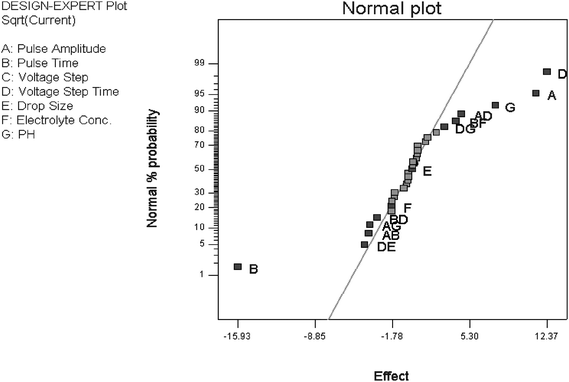 | ||
| Fig. 1 Normal probability plot of effects for the quarter-fractional factorial design (27-2) for DPP analysis of TBM. | ||
It can be observed in Fig. 1 that the parameters of A, D and G affect the voltammetric response in a positive way, but B influences the DPP response in a negative way. Besides the main effects, second order interactions also influence the voltammetric response. Voltage step (C), drop size (E), and electrolyte concentration (F) show no significant effects. It should be noted that the interaction of B and F shows some contributions to the voltammetric response. Therefore, voltage step and drop size were fixed in their mean values, i.e. 0.005 V and 2 μm2, respectively. In order to choose the best value for the electrolyte concentration, solutions with different concentrations of the electrolyte were examined in two different conditions. There was no significant effect on the response when the electrolyte concentration was set between 0.07 and 0.1 M. Therefore, the electrolyte concentration was fixed on 0.09 M and for the optimization of DPP a central composite design was applied by using the remaining four factors of A, B, D, and G.
3.3. Response surface study
In the next step, a rotatable central composite design (CCD) was employed to determine the optimal conditions for the critical factors. This design permitted the response surface to be modelled by fitting a second-order polynomial using (2f + 2f + n) experiments, where f is the number of factors and n is the number of runs performed in the center. In this study, f and n were set at 4 and 6, respectively. This means that a total of 30 experiments was performed, out of which 6 experiments were repeated in the center of the design.The axial spacing of a = ±2 was calculated to satisfy the rotatability of the design. The experiments were run in a random manner, in order to minimize the effect of uncontrolled variables on the response.27 The level of factors used in the CCD and the corresponding design matrix and responses are shown in Tables 3 and 4, respectively.
| Factor notation | Factor | Levels | ||||
|---|---|---|---|---|---|---|
| −2 | −1 | 0 | 1 | 2 | ||
| A | Pulse Amplitude/V | 0.04 | 0.08 | 0.12 | 0.16 | 0.2 |
| B | Pulse Time/s | 0.01 | 0.02 | 0.03 | 0.04 | 0.05 |
| G | Sample pH | 3.2 | 3.5 | 3.8 | 4.1 | 4.4 |
| D | Voltage Step Time/s | 0.7 | 1 | 1.3 | 1.6 | 1.9 |
| Run | A | B | G | D | Response (I/nA) |
|---|---|---|---|---|---|
| 1 | 1 | 1 | −1 | 1 | 2327 |
| 2 | 0 | 0 | 0 | −2 | 907 |
| 3 | −2 | 0 | 0 | 0 | 511 |
| 4 | −1 | −1 | 1 | −1 | 1311 |
| 5 | 1 | −1 | 1 | 1 | 2648 |
| 6 | −1 | 1 | 1 | 1 | 1297 |
| 7 | 0 | 0 | 2 | 0 | 1438 |
| 8 | 2 | 0 | 0 | 0 | 1799 |
| 9 | 0 | 0 | 0 | 0 | 1426 |
| 10 | 1 | 1 | −1 | −1 | 1615 |
| 11 | 0 | 0 | 0 | 0 | 1427 |
| 12 | 0 | 0 | −2 | 0 | 2083 |
| 13 | 1 | −1 | −1 | −1 | 2481 |
| 14 | 0 | 0 | 0 | 0 | 1427 |
| 15 | 0 | 2 | 0 | 0 | 1058 |
| 16 | 1 | 1 | 1 | −1 | 1267 |
| 17 | 1 | −1 | −1 | 1 | 3865 |
| 18 | 1 | 1 | 1 | 1 | 1907 |
| 19 | −1 | −1 | −1 | −1 | 1573 |
| 20 | 0 | 0 | 0 | 0 | 1461 |
| 21 | −1 | 1 | −1 | 1 | 1506 |
| 22 | −1 | −1 | 1 | 1 | 1803 |
| 23 | 1 | −1 | 1 | −1 | 1870 |
| 24 | −1 | −1 | −1 | 1 | 2124 |
| 25 | 0 | 0 | 0 | 2 | 1918 |
| 26 | −1 | 1 | 1 | −1 | 956 |
| 27 | −1 | 1 | −1 | −1 | 1042 |
| 28 | 0 | 0 | 0 | 0 | 1502 |
| 29 | 0 | −2 | 0 | 0 | 2824 |
| 30 | 0 | 0 | 0 | 0 | 1466 |
As final step, a response surface model was developed by considering all the responses in the CCD. The regression calculations were performed by means of Design Expert software to fit all of the polynomial models to the CCD data. For data analysis, a power of 0.63 was used for the transformation of the responses. This improved the statistical properties of the analysis. In developing the final model, main effects, two and higher order interaction effects and curvatures were applied in coded forms. Then, the model with the most reasonable statistics, i.e. higher F- and R-values and low standard error was considered as the satisfactory response surface model. Therefore, the quadratic model was selected as the most appropriate one. The statistical significance of the model and its terms were determined by the analysis of variance (ANOVA) that confirms the adequacy of the quadratic model (Table 5). The model consisted of four main effects, six two-factor interaction effects and four curvature effects. The following equation is the ultimate model resulting from the ANOVA analysis in terms of coded factors for the peak current:
| (Current)0.63 = +98.16 + 15.22 × A − 14.90 × B − 7.48 × G + 12.21 × D − 2.12 × A2 + 6.20 × B2 + 5.08 × G2 + 1.23 × D2 − 3.04 × A × B − 3.43 × A × G + 2.96 × A × D + 2.55 × B × G − 1.51 × B × D − 1.42 × G × D | (Eq. 1) |
| Source | Sum of Squares | DF | Mean Square | F Value | Prob > F |
|---|---|---|---|---|---|
| Model | 18353.73 | 14 | 1310.98 | 20.38 | <0.0001 |
| A | 5558.94 | 1 | 5558.94 | 86.43 | <0.0001 |
| B | 5326.34 | 1 | 5326.34 | 82.81 | <0.0001 |
| G | 1341.98 | 1 | 1341.98 | 20.87 | 0.0004 |
| D | 3576.27 | 1 | 3576.27 | 55.60 | <0.0001 |
| A2 | 122.78 | 1 | 122.78 | 1.91 | 0.1873 |
| B2 | 1053.23 | 1 | 1053.23 | 16.38 | 0.0011 |
| G2 | 709.22 | 1 | 709.22 | 11.03 | 0.0047 |
| D2 | 41.54 | 1 | 41.54 | 0.65 | 0.4342 |
| AB | 147.71 | 1 | 147.71 | 2.30 | 0.1504 |
| AG | 187.75 | 1 | 187.75 | 2.92 | 0.1081 |
| AD | 140.51 | 1 | 140.51 | 2.18 | 0.1601 |
| BG | 103.82 | 1 | 103.82 | 1.61 | 0.2232 |
| BD | 36.27 | 1 | 36.27 | 0.56 | 0.4643 |
| CD | 32.10 | 1 | 32.10 | 0.50 | 0.4907 |
| Residual | 964.76 | 15 | 64.32 | ||
| Pure Error | 8.50 | 5 | 1.70 | ||
| Cor Total | 19318.49 | 29 | |||
| Std. Dev. | 8.019809 | R-Squared | 0.95006 | ||
| Mean | 106.4753 | Adj R-Squared | 0.90345 | ||
| C.V. | 7.532085 | Pred R-Squared | 0.714247 | ||
| PRESS | 5520.317 | Adeq Precision | 20.10203 | ||
The adequacy of fit of the model could be checked by different criteria. The F value of 20.38 implies that the model is significant. This means that there is only 0.01% chance that a model with an F value this large could occur due to noise. The statistical significance of the model was also confirmed by the coefficient of determination of the model (R2 = 0.95) which implies that only 5.00% of the variability in the response is not explained by the model.27,28
Values of “Prob. > F” less than 0.0500 indicate that the model terms are significant. Therefore, A, B, D, G, B2 and G2 are significant terms in the model. In eqn (1), the coefficients for pulse amplitude (A) and voltage step time (D) are large and positive. This shows that the current increases extensively with increasing these variables. On the other hand, pulse time (B) and sample pH (G) appear with a negative coefficient. The negative sign indicates that these two variables have opposite effects on the current, and also the absolute value of pH coefficient is less than other main coefficients. Except for the sample pH (G), the behavior of all other factors influencing the voltammetric responses is the same using Q-FFD or CCD procedures. We believe that this may be due to a drawback of the Q-FFD with using a small number of experiments and a shorter range for variation of pH for choosing the important factors among relatively large number of factors (f = 7). The effect of curvature in the response surface model appears in the coefficients for A2, B2, D2 and G2. In comparison to other coefficients, these coefficients are relatively small. This indicates that the response surface is more planar and the curvature plays a minor role in this respect.
Inspection of the results indicates that there are six interacting factors affecting the value of the current, but they are not significant. In order to assess their effects, the 3-dimensional plots of these terms are demonstrated for a function of two factors at a time, holding all other factors fixed at their center levels (Fig. 2). The perturbation plot (Fig. 3) provides silhouette views of the response surface. It shows how the response changes as each factor moves from the chosen reference point, with all other factors held constant at a reference value. According to the regression equation, the maximum response could be obtained using 0.18 (V), 0.01 (s), 3.2, and 1.8 (s) levels for the pulse amplitude, pulse time, sample pH and voltage step time, respectively.
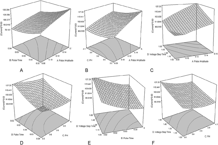 | ||
| Fig. 2 3D surfaces and contour plots of the DPP current in analysis of TBM. (A) The interacting effect of pulse time and pulse amplitude. (B) The interacting effect of pulse amplitude and sample pH. (C) The interacting effect of voltage step time and pulse amplitude. (D) The interacting effect of pulse time and sample pH. (E) The interacting effect of voltage step time and pulse time. (F) The interacting effect of voltage step time and sample pH. | ||
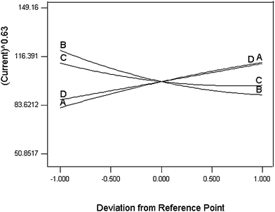 | ||
| Fig. 3 Design-Expert perturbation plot for DPP analysis of TBM: pulse amplitude (A), pulse time (B), voltage step (C), voltage step time (D). | ||
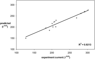
In order to show the predictive ability of the CCD model, fourteen additional treatments which were not among the ones applied for developing the model were chosen. The levels of factors for these experiments were near to optimum levels. Fig. 4 shows the predicted values for the DPP peak currents vs. the experimental values for these treatments. The value of 0.9213 for the R2 of the plot indicates the predictive ability of the model.
 | ||
| Fig. 4 Predicted values of DPP peak current versus experimental values. | ||
The optimum values for the levels of factors effecting the DPP current obtain by CCD method are shown in Table 6. It should be noted that the optimum conditions obtain by the method are not among the ones chosen for the design. In this way, the optimization process using a 27-2 quarter-factorial design followed by developing a response surface allowed the estimation of the factor values that provide better responses. However, to reach the optimum conditions, much fewer experiments were needed in the experimental design compared to the one-at-a-time technique. In addition, to obtain accurate results in such experiments with a lot of factors with one-at-a-time technique is not possible, especially when the second order interactions influence the response.
| Electrolyte Conc./mol L−1 | Voltage Step/V | Drop size/μm2 | Pulse Amplitude/V | Pulse Time/s | Sample pH | Voltage Step Time/s |
|---|---|---|---|---|---|---|
| 0.09 | 0.005 | 2 | 0.18 | 0.01 | 3.2 | 1.80 |
In order to verify the effect of the sample pH which was in contradiction between CCD compared to the Q-FFD, five additional treatments were applied by varying the sample pH and keeping all other factors at their optimum values. Fig. 5 demonstrates the results. When we were performing the 27-2 design, we were not able to extend the value of pH lower than 3.6 due to the presence of the buffer. However, in the case of CCD, the concentration of electrolyte was lower and, therefore, having a pH as low as 3.2 was possible. Fig. 5 shows that the peak current is minimum when the sample pH is 3.8, while the CCD results showed that its optimum value is 3.2. This means that the contradiction between the two techniques regarding the pH is due to the variation of the levels of this parameter.
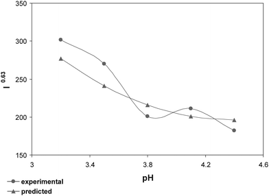 | ||
| Fig. 5 The effect of sample pH on optimization condition for DPP analysis of TBM. | ||
To evaluate the accuracy of the results obtained by the response surface model, seventeen experiments were carried out under the optimum conditions. A linear relationship between the peak current and concentration was obtained between 0.07 and 20 mg L−1. The LOD, LOQ and RSD% were 36 μg L−1, 119 μg L−1 and 2.7, respectively. These results show that one may use the experimental design to optimize the levels of parameters affecting the DPP technique, preparing this method as a powerful tool for the determination of TBM at a trace level.
The present optimized procedures were also successfully applied to the determination of TBM in soil and wheat. The extraction of TBM from soil and wheat was carried out by ultrasonic extraction (USE). After extraction, the solvent was evaporated and without any clean-up, the concentration of TBM was measured under the optimum conditions previously described for DPP. The RSD from ten repeated measurements of electrochemical signals of TBM for soil and wheat were 0.04 and 0.05, respectively. Mean recovery and LOD for the extraction from soil and wheat were 99.8%, 6 μg g−1 and 98.2%, 4 μg g−1, respectively. These values confirmed the sensitivity of the proposed method for the determination of TBM in spiked samples compared to the GC and HPLC methods.5,7,8
Results show that polarographic determinations can be carried out in heterogeneous mixtures containing slightly soluble particles. In such solutions or suspensions, it is possible to carry out the determination directly in the mixture without pre-separations. The results are compared with chromatographic techniques. The main advantage of the proposed DPP method over the chromatographic techniques is that the DPP method is fast and requires easy operation and simple instrumentation. The analysis can be routinely carried out in under 3 min. This renders the electroanalytical methods as superior for analyzing large numbers of samples, as they are timesaving. Moreover, the instrumentation for chromatography techniques is expensive and the running costs are high. The polarography methods are also selective and environmental friendly because it uses few ml of solvent and the analysis runs mostly in aqueous medium.
4. Conclusion
In this work, the influence of various parameters affecting the DPP current of the TBM reduction was studied by using experimental design. The results show that using factorial design and CCD to optimize the voltammetric parameters for the determination of TBM enhances the response and increases the sensitivity of the method in a significant way. Also, the linear response range has been improved and amplified and to reach the optimum conditions, a fewer number of experiments were needed. On the other hand, since the interaction of factors and the curvature effects are included in the studies, the optimum conditions found by designing the experiments are more reliable compared with the one-at a-time method.The sensitivity of the optimized DPP was comparable with those observed for the chromatographic ones. The main advantage of such a procedure is the possibility of determining the concentration of the active component directly from the pesticide formulation, soil or wheat without the need for any prior steps such as clean-up, or pre-concentration which are tedious, time consuming, and also polluting. Moreover, no organic solvents are needed and the analysis is carried out in aqueous medium. The present method could possibly be applied for the determination of TBM in other environmental samples as well as for quality control laboratories.
Acknowledgements
This work was supported by the Geological Survey and the Research Council of Shahid Beheshti University of Iran. We gratefully acknowledge Dr S. Evazmoghadam and Dr M. Agha Mohammadi for their kind help and comments.References
- J. Liu, J. Chao, G. Jiang, Y. Cai and J. Liu, J. Chromatogr., A, 2003, 995, 21 CrossRef CAS.
- C. Olmedo, L. Deban, M. Caco, M. Vega and F. De la Rosa, Fresenius J. Anal. Chem., 1997, 357, 962 CrossRef CAS.
- A. K. Sarmah and J. Sabadie, J. Agric. Food Chem., 2002, 50, 6253 CrossRef CAS.
- J. L. Barnel, J. J. Jimenéz and J. Atienza, J. Chromatogr., A, 1997, 778, 119 CrossRef CAS.
- A. K. Bhattacherjee and P. Dureja, Pestic. Sci., 1999, 55, 183 CrossRef CAS.
- P. Degelmann, J. Wenger, R. Niesssner and D. Knopp, Environ. Sci. Technol., 2004, 38, 6795 CrossRef CAS.
- J. Chaoa, J. Liu, M. Wen, G. Liu, Y. Caia and G. Jiang, J. Chromatogr., A, 2002, 955, 183 CrossRef.
- Q. Zhou, J. Liu, Y. Cai, G. Liu and G. Jiang, Microchem. J., 2003, 74, 157 CrossRef CAS.
- E. T. Furlong, M. R. Burkhardt, P. M. Gates, S. L. Werner and W. A. Battaglin, Sci. Total Environ., 2000, 248, 135 CrossRef CAS.
- S. Polati, M. Bottaro, P. Frascarolo, F. Gosetti, V. Gianotti and M. C. Gennaro, Anal. Chim. Acta, 2006, 579, 146 CrossRef CAS.
- R. Curini, A. Gentili, S. Marchese, A. Marino and D. Perret, J. Chromatogr., A, 2000, 874, 187 CrossRef CAS.
- E. Ayano, H. Kanazawa, M. Ando and T. Nishimura, Anal. Chim. Acta, 2004, 507, 211 CrossRef CAS.
- P. Degelmann, S. Egger, H. Jürling, J. Müller, R. Niesssner and D. Knopp, J. Agric. Food Chem., 2006, 54, 2003 CrossRef CAS.
- F. Menzinger, Ph. Schmitt-Kopplin, D. Freitag and A. Kettrup, J. Chromatogr., A, 2000, 891, 45 CrossRef.
- P. Manisankar, S. Viswanathan, A. M. Pusphalatha and C. Rani, Anal. Chim. Acta, 2005, 528, 157 CrossRef CAS.
- M. S. Ibrahim, K. M. Al-Magboul and M. M. Kamal, Anal. Chim. Acta, 2001, 432, 21 CrossRef CAS.
- R. İnam, E. Z. Gülerman and T. Sangül, Anal. Chim. Acta, 2006, 579, 117 CrossRef CAS.
- M. C. Corredor, J. M. Rodriguez Mellado and M. Ruiz Montoya, Electrochim. Acta, 2006, 51, 4302 CrossRef CAS.
- R. İnam, T. Sangül, E. Z. Gülerman and N. Uncu, Int. J. Environ. Anal. Chem., 2006, 86, 1135 CrossRef CAS.
- L. Pospíšil, R. Trsková, R. Fuoco and M. P. Colombini, J. Electroanal. Chem., 1995, 395, 189 CrossRef.
- M. Drevinek and V. Horak, J. Electroanal. Chem., 1997, 423, 83 CrossRef CAS.
- P. Zuman, Microchem. J., 2002, 72, 241 CrossRef CAS.
- B. L. Ruiz and P. S. Pedrero, Analyst, 1994, 119, 2377 RSC.
- B. L. Ruiz, G. Frutos, P. S. Pedrero and J. P. Martín, Analyst, 1993, 118, 59 RSC.
- R. F. Teófilo, E. L. Reis, C. Reis, G. A. da Silva and L. T. Kubota, J. Braz. Chem. Soc., 2004, 15, 865 CAS.
- M. Mousavi, E. Noroozian, M. Jalali-Heravi and A. Mollahosseini, Anal. Chim. Acta, 2007, 581, 71 CrossRef CAS.
- E. Morgan, Chemometrics: Experimental Design, John Wiley, London, 1991 Search PubMed.
- S. Ghasempur, S. F. Torabi, S. O. Ranaei-Siadat, M. Jalali-Heravi, N. Ghaemi and K. Khajeh, Environ. Sci. Technol., 2007, 41, 7073 CrossRef CAS.
| This journal is © The Royal Society of Chemistry 2010 |