The differentiation and engraftment potential of mouse hematopoietic stem cells is maintained after bio-electrospray
Kerol
Bartolovic
a,
Napachanok
Mongkoldhumrongkul
b,
Simon N.
Waddington
c,
Suwan N.
Jayasinghe
*b and
Steven J.
Howe
a
aWolfson Centre for Gene Therapy, Molecular Immunology Unit, UCL Institute of Child Health, University College London, 30 Guilford Street, London, UK WC1N 1EH
bBioPhysics Group, Department of Mechanical Engineering, University College London, Torrington Place, London, UK WC1E 7JE. E-mail: s.jayasinghe@ucl.ac.uk; Fax: +44 2073880180; Tel: +44 2076792960
cInstitute for Women's Health, University College London, 86-96 Chenies Mews, London, UK WC1E 6HX
First published on 13th November 2009
Abstract
The bio-electrospray technique has been recently pioneered to manipulate living, immortalised and primary cells, including a wide range of stem cells. Studies have demonstrated that the creation of viable, fully functional in vitro microenvironments is possible using this technique. By modifying the bio-electrospray procedure (referred to as cell electrospinning), a variety of microenvironment morphologies have been fabricated. Because bio-electrospraying of biological material is a relatively new technique, it is important to determine if there are any unwanted consequences to the manipulated cells as a result of the procedure. Here, we establish the validity of the process using a heterogeneous, living population of hematopoietic stem/progenitor cells, using a functional in vitro assay and in vivo mouse model to investigate for side-effects that previous in vitro assays may not have detected. Our studies demonstrate that these bio-protocols have no obvious negative effects, thus indicating significant promise for utility in biological sciences and for a plethora of healthcare applications.
Introduction
Electrosprays and electrospinning1,2 have been developed over several decades. The technologies have been explored for a wide range of applications spanning aerosol sciences to those directed towards materials sciences and engineering, and more recently to biological research and development (referred to as bio-electrospraying).3–9 One such notable contribution was the work carried out with electrosprays by Fenn10 who applied the technique to deliver biomolecules into a mass spectrometer to determine their charge and mass and so identify molecular characteristics. The technology has created a paradigm shift in molecular recognition techniques where this approach has now become a standard protocol for accurately identifying biomolecules, and is thus applicable to many areas of research including proteomics and cancer related areas of research. Bio-electrospraying also has potential for producing matrices of cells embedded in materials that could form artificially engineered tissues and organs. However, previous research with both bio-electrosprays and cell electrospinning has not assessed the biological impact of the procedure by functional assays. Other methodologies are available to directly handle living cells via needle-based approaches, namely, ink-jet printing,11 laser guided cell writing,12 aerodynamically assisted bio-jetting13 and pressure assisted cell spinning.14 Ink-jet printing can unfortunately have detrimental effects on the viability of treated cells. Cell mortality (not taking into account early apoptotic cells) has been shown to be approximately 70% using this method.15 In comparison, we have performed cell viability and integrity studies from a genetic level upwards on bio-electrosprays, cell electrospinning, aerodynamically assisted bio-jets (and bio-threads) and pressure assisted cell spinning which have shown cell viability over 70%.16,17 These studies demonstrate the requirement for further testing with well-established techniques such as flow cytometry to fully and accurately identify the actual viable population of cells post-treatment in comparison to controls over both short and long time points. In addition to flow cytometry, cytogenetic and gene expression studies are important tests for these techniques. Here, we have performed a more detailed investigation of bio-electrosprays, which were developed in 2005 by Jayasinghe et al.16,17 Since then, the procedure has been refined to improve jet stability and continuity,18 to enable formation of multicellular encapsulations of different morphologies19 and to allow handling of developing multicellular model organisms.20,21 Those studies demonstrated, in comparison to controls, maintenance of cell viability and embryo development was not perturbed either by the high intensity electric field nor the physical manipulation.In this study we further investigate the application of bio-electrosprays by studying functional in vitro differentiation of hematopoietic progenitor cells and assess in vivo engraftment of stem cells in a mouse model. These investigations confer additional sensitivity over simple viability assays, providing a functional readout and testing the technique in a biologically relevant setting. For in vitro testing, bone marrow (BM) was extracted from mice and subsequently bio-electrosprayed. The post-treated cells were compared in in vitro colony forming assays to assess whether the ability of stem cells found in BM to differentiate into myeloid cell lineages was affected. Treated mouse BM cells were also injected into lethally irradiated recipient mice. BM contains a range of cells, including self renewing stem/progenitor cells that can also differentiate to produce all the different cell types found in blood. Examining the survival of these animals along with the repopulation of the blood system provides a more detailed analysis of the effect bio-electrospraying has on cells.
Experimental
Bio-electrospray equipment set-up and operation
The bio-electrospray device explored in these studies (Fig. 1) was the coaxial system which allows the delivery of cells in either single or the coaxial needle system. The coaxial or concentric needle system allows the flow of an outer flowing secondary liquid. In our previous experiments this has been used for achieving jet stability to improve the ability to generate continuous cell-bearing fibres to scaffolds and membranes.19,22 Essentially this unique coflow configuration allows the shielding of the high conducting and low viscosity properties of cell suspensions, which have been shown to be the main parameters contributing to instability in the jetting process.16,17 Additionally, manipulation of the outer flowing polymer properties can be explored through the modulation of its rheological properties to assist in forming either cell-bearing droplets19 or cell-containing continuous fibres; the latter process is now referred to as cell electrospinning.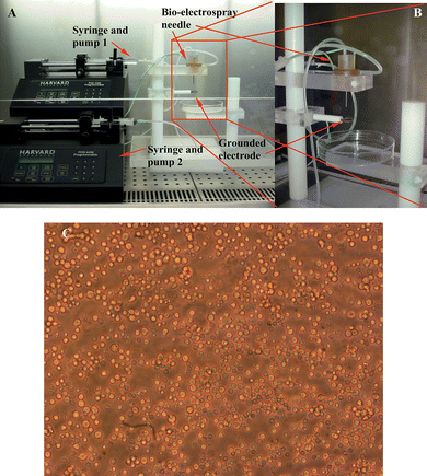 | ||
| Fig. 1 Digital images of the bio-electrospray equipment arrangement in a laminar flow safety cabinet. Panel A) shows the entire bio-electrospray set-up which can be modified for cell electrospinning, B) illustrates the coaxial device utilised in these studies and C) a representative micrograph of the heterogeneous cell population derived from hematopoietic progenitor cells of CD-1 mouse BM. | ||
In these investigations the coaxial system was arranged in the laminar flow safety hood as shown in Fig. 1. The ring shaped ground electrode was placed ∼20mm centrally below the needle exit. The inlet of the inner needle to the device was connected to a precision syringe pump (PHD 4400, HARVARD Apparatus Ltd., Edenbridge, UK) capable of controlling a consistent and continuous flow of media ranging from ∼10−7-10−20m3s−1, which was varied with the adjustable pump flow rate and syringe cross sectional area. The needle was also connected to a high voltage power supply (FP-30, Glassman Europe Ltd, Tadley, UK), capable of applying a voltage of ±30kV with a resolution of ∼0.5kV. The power supply had a maximum delivery current of ∼4mA.
Different parameters were tested to establish the behaviour of the jetting process with the aid of a digital high-speed video camera (Vision Research PHANTOM V7.3, capable of capturing 500000fps, on loan from the EPSRC loan pool). This image capturing technique allowed us to visualise the jetting process in real-time for any given operational parameter setting. In addition these images showed us how to control the jet so that there is less whipping of the jet, which can contribute to the loss in cell numbers during collection. In these studies we tested a large operational window ranging from ∼10−9-10−15m3s−1 for the flow rate and for an applied voltage from ±1–30kV. In our trial runs we found that the generated cell-bearing droplet plumes were difficult to control and collect onto a sterile collecting vessel, therefore we inserted a 15ml centrifuge tube into the ground electrode which significantly reduced cell loss and resulted in near-complete cell collection.
Animal welfare
All animal experiments were performed under UK Home Office license following authorised procedures. Before applying for a license, an official requirement for each project is submission to an Institutional ethical review panel. This local board comprises a veterinary surgeon, a Named Animal Care and Welfare Officer, and a layperson, who must accept the application prior to submission to the Home Office.Bone marrow (BM) extraction from CD-1 mice
After culling mice at 8 weeks of age, adhering to Home Office procedures, the skin and muscle covering the legs were removed. The tibia and femur were isolated by removing the ends of the bones to expose the medullary cavity, where marrow cells are located. BM cells were harvested from tibias and femurs by inserting a 25 gauge needle into the cavity and flushing the cells out with a syringe containing approximately 1ml of IMDM medium (Cat. No. 21980, http://www.invitrogen.com/GIBCO), before passing through a 70µm cell strainer to remove debris (Fig. 1C). Erythrocytes were eliminated using Red Cell Lysing Buffer (1X RBC Lysis Buffer, Cat. No, 00-4333, http://www.ebioscience.com) following the manufacturer's instructions.In vitro methylcellulose progenitor assay for colony-forming units
The quantity and quality of lineage-committed progenitors in mouse bone marrow (BM) were assessed using a semi-solid methylcellulose plating assay (MethoCult M3434, StemCell Technologies, UK).23 Red blood cells were eliminated by resuspending the BM pellet in 1ml of 1X RBC lysis buffer. Following an incubation at room temperature for 5 minutes, 6 ml of phosphate buffered saline was added to stop the reaction and re-centrifuged at 300xg for 5 mins. The resulting pellet of cells was resuspended in 1ml of IMDM (Cat. No. 21980, http://www.invitrogen.com/GIBCO) and total live cell number was assessed by Trypan Blue staining (described below). Untreated (CC, Culture controls), and bio-electrosprayed (BES) BM cells were prepared at a cell density of 6 × 10⁴ cells in 300 µl of medium and added into a 3ml aliquot of methylcellulose each. The methylcellulose cell suspension was vigorously vortexed. Tubes were left to settle at 37 °C for ∼10 minutes until the semisolid methylcellulose became clear. 2 × 10⁴ mouse BM cells were plated in 1.1ml semisolid methylcellulose progenitor culture medium into 35mm plate (duplicates). After 16 to 20 days of culture at 37 °C in a humidified atmosphere with 5% CO2, plates were assessed by microscopy for the presence of erythroid (erythroid burst-forming units (BFU-Es)) and myeloid colonies (colony forming unit-granulocyte (CFU-G), CFU-macrophage (CFU-M) and CFU-granulocyte macrophage (CFU-GM)).Cell viability assessment
Cell viability was assessed by Trypan Blue staining (SIGMA, UK, T8154). which is based on the assumption that dead cells have a damaged cell membrane and so cannot exclude the dye. Viable cells maintain a clear cytoplasm when mixed with Trypan Blue whereas dead or damaged cells are stained blue. One part cell suspension was mixed with one part Trypan Blue (0.4%) and left for 1 minute before counting live and dead cells using a hemocytometer on a light microscope (Nikon Eclipse TS100, Nikon UK Limited, UK).Assessment of engraftment in CD-1 mice
CD-1, 8-week-old female mice (a minimum of 3 animals per condition to be tested) were maintained, 2 to 3 mice per sterile individually ventilated cage under temperature- and humidity-controlled conditions with food and water ad libitum. Mice were lethally irradiated with a split dose at 24 hours and 2 hours prior to injection (600 rads and 400 rads respectively) to eradicate existing bone marrow cells. 1 × 10⁶ treated or control BM donor cells were resuspended in PBS and injected (0.2 ml volume) into lateral tail veins. Engraftment was analyzed 8 to 9 weeks after injection of cells and unmanipulated wild-type mice were used as controls. Mice were sacrificed, peripheral blood, spleen, and both femurs and tibiae were removed and flushed with IMDM cell culture medium. All procedures were performed under license and according to UK Home Office regulations. Harvested cells were incubated in red blood cell lysis buffer as previously described, resuspended in IMDM cell culture medium, and counted using a hemocytometer.Flow cytometry
Flow cytometry analysis was performed using a LSR II cytometer and FACSDiva software (Becton Dickinson). Cells were resuspended in 2% fetal bovine serum (FBS) in PBS (Phosphate buffer saline), and stained with murine anti-CD3e FITC (Fluorescein isothiocyanate), anti-CD4 PE (phycoerythrin), anti-CD8 APC (allophycocyanin) to identify different subsets of T lymphocytes, anti-B220 APC (BD Pharmingen, San Jose, CA) to identify B lymphocytes, and anti-CD11b PE (http://www.ebioscience.com) to identify myeloid cells such as macrophages and granulocytes. DAPI (1µgml−1) was used to exclude non-viable cells.Blood analysis
Whole peripheral blood was collected in sodium citrate (3.8%) and levels of different parameters were measured using an MS95 vet hematology analyser (Woodley Equipment Company Ltd).Statistical analysis
Data presented in Figs. 4 and 5 [reconstitution data and blood analysis] are shown as percentages. To perform statistical analyses, the data were first normalised by the standard procedure of deriving the inverse sine of the square root of each percentage and then analysed by general linear model (GLIM) with Tukey pairwise comparisons (Minitab). For spleen masses, data were analysed by GLIM and Tukey pairwise comparisons. For colony-forming unit assays and cell viability counts, chi-square analysis was performed on raw counts pooled from separate experiments.Results and discussion
Bio-electrospraying hematopoietic stem cells
Several aliquots of cells were jetted using a wide range of operational parameters to determine the optimal configurations for stable jetting. Jet stability is necessary for future applications such as pin-point precision deposition of single or heterogeneous cellular populations, but at this time viability and functionality takes precedence. As expected, using a single needle to test a wide spectrum of applied voltages and flow rates did not lead to stable jetting of these cells.16,17 The jetting characteristics in these unstable conditions varied from generating cell-containing droplets to fragments (Fig. 2). However, jet stability and continuity was attained in the coaxial configuration with the co-flow of a medical grade polydimethylsiloxane (PDMS) or a biopolymer.18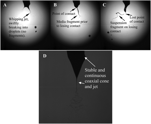 | ||
| Fig. 2 Characteristic high-speed digital images of the bio-electrospray process in action. Panel A) depicts the unstable jetting process which is taking place at a flow rate of ∼10−11m3s−1 for an applied voltage of ∼7kV. Panels B and C) depict the jetting at the same voltage but at increasing flow rates of ∼10−10 and ∼10−9m3s−1. In B) and C) the increase in flow rate is seen to give rise to a longer jet/fragment formation. Panel D) represents stable jetting in the coaxial needle configuration. | ||
For a given applied voltage, variations in the flow rate changes the behaviour of the exiting cell suspension. In one particular scenario, a voltage constant of ∼7kV was applied while varying the flow rate from ∼10−11, ∼10−10 and ∼10−9m3s−1. We found that at the lower flow rate the unstable jet was forming near the needle exit while at the highest flow rate it was further away from the needle exit but gave rise to the formation of media fragments, due directly to the increased flow rate (Fig. 2A–C). Maintaining the flow rate at ∼10−11 m3s−1 whilst increasing the applied voltage produced instantaneous cone and jet(s) to form at the needle exit, which were shallower and the period of formation increased in line with the generation of smaller cell-containing droplets. Increasing the applied voltage for a given flow rate was also seen to give rise to the varying modes of bio-electrospraying, which ranged from unstable single jets, multiple jet formation with spindle and rimmed emission modes. These have previously been reported but only for stable cone-jet mode conditions.24 As shown by our previous studies, these variations in jetting modes do not have any effects on the post-treated cells16,17 but do cause problems in the collection of the jetting cells. We also noted that reaching an applied voltage of ∼12kV gave rise to discharging effects, which showed the crossing of sparks between the electrodes. At this stage cell collection was ceased and the process was discontinued.
Therefore, for the remainder of these studies the cell suspensions were subjected to an applied voltage of ∼8kV for a flow rate of ∼10−9 m3s−1. These conditions not only allowed the safe collection and the minimum loss of cells during jetting and collection, but also did not have any discharging effects present (Fig. 3).
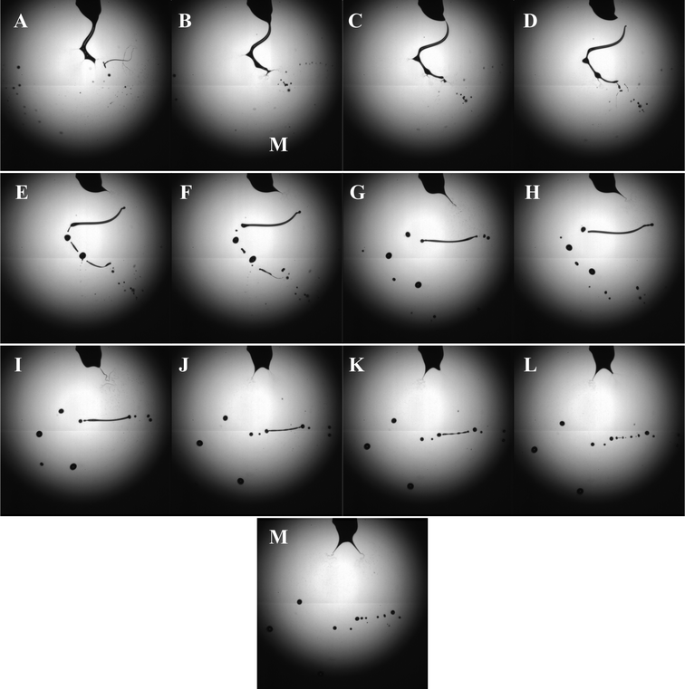 | ||
| Fig. 3 Characteristic high-speed digital images captured during the bio-electrospray process at the applied voltage and flow rate of ∼8kV and ∼10−9 m3s−1 respectively. The images depict the ramified mode of unstable jetting of the cell suspension (Panels A-D) with the subsequent cell suspension column undergoing coulomb fission (Panels E-M). | ||
High-speed digital photography was used to image the jetting process, revealing an interesting set of events. Panels A-D in Fig. 3 demonstrate the unstable jetting process which upon acceleration towards the ground electrode gives rise to several secondary jets from staggered points along the primary jet. This has been previously documented and referred to as the ramified mode of jetting.24 In panel D, the cell suspension column is seen to lose contact with the needle, undergoing “coulomb fission” (Panels E-M, in Fig. 3).25 This occurs when the bio-electrospray process produces an excess surface charge over surface tension, causing the medium to undergo an explosion. In panels E-M in Fig. 3 the jetting process at the needle is seen to fluctuate from a single jetting process to a multiple jetting scenario, which exemplifies the instability in the jetting process in the single needle configuration. The oscillating jet depicts behaviour similar to that previously reported for the multi-spindle mode of jetting.24 Once again, this was only reported in stable jetting conditions, but as demonstrated here, similar morphologies do also exist in the unstable jetting conditions.
Cell viability is maintained after bio-electrospraying
Bone marrow (BM) was flushed from mouse legs and the viability of the cells was calculated using a Trypan Blue staining and counting using a hemocytometer on a light microscope (Leica DMI3000 B, Milton Keynes, UK). This was repeated after manipulating the samples: cells subjected to the bio-electrospray (BES) were compared to cells that had not been passed through a needle but just cultured for the same period of time (negative untreated culture control; CC). There was no significant difference between the viability of the BES samples and CC controls (mean viability for BES = 84.8%, CC mean viability = 86.4%: p = 0.613, chi square test).The bio-electrospray process has no impact on the colony-forming capacity of mouse bone marrow cells
The impact of the bio-electrospraying mouse hematopoietic progenitor cell growth and differentiation was investigated using an in vitro, semisolid methylcellulose clonal colony assay. In this medium, committed progenitors in the bone marrow population can differentiate into various myeloid cell lineages that constitute the blood. These form colonies in the semi-solid culture medium that give an indication of the differentiation capacity of the cells, which can be altered through culturing or physical manipulation. The bio-electrospray process has no significant impact on colony forming unit (CFU) potential of mouse BM cells compared to untreated CC control BM cells (chi square test, p = 0.97, Table 1). The viability of the cells and the potential to differentiate into a range of blood cell lineages were unaffected by the process.Bio-electrosprayed cells have the capacity to reconstitute the murine hematopoietic system in vivo
Manipulated cells (BES or CC) were injected into lethally irradiated mice, which were analysed 8 weeks later. The dose of radiation received by the mice was sufficient to eliminate bone marrow stem cells and if injected donor cells do not engraft and repopulate the blood system, the mice would die. Blood samples from the mice show that on average, levels of several parameters (including lymphocyte, and myeloid cells) were unchanged between bio-electrosprayed cells and controls and comparable to cells taken from untreated wild-type (WT) mice that had not received a transplant (Fig. 4A and 4B). The spleen is responsible for initiating blood-borne defences and its size is an indicator of hematopoiesis and health. Post-mortem examination of transplanted recipients revealed spleen sizes to be comparable to those of untreated, wild-type mice, with no significant differences between the controls and bio-electrosprayed subjects (Fig. 4C, GLIM/Tukey pairwise analysis test, p = 0.786). Bone marrow, spleen and peripheral blood of recipients were harvested and both myeloid and lymphoid reconstitution derived from the donor cells was determined by flow cytometry. This gave an indication of whether the stem cells or committed progenitor cells had been affected by the jetting procedure as any damage to the cells could alter their homing, engraftment or differentiation potentials. There is no significant difference between the proportions of myeloid cells, B cells and T cells in control mice (CC) and the recipients of cells subjected to bio-electrospraying (BES) for any cell type examined in the peripheral blood, bone marrow or spleen (Fig. 5). The levels of each population studied follow the same general pattern as those in wild-type mice suggesting no gross abnormalities, even after the manipulation and transplantation procedure. Where there is a difference between the experimental animals and the wild–type mice, it is noted on the graph and the p-value shown.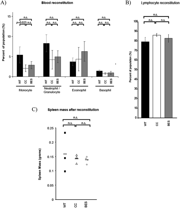 | ||
| Fig. 4 Bone marrow cells were either subjected to bio-electrospray (BES), or were unmanipulated (CC) before injection into lethally irradiated mice. 8–9 weeks later, levels of different cell types in peripheral blood composition were analysed. All experimental animals were compared against untransplanted wild-type (WT) controls; (A) Monocytes, neutrophils/granulocytes, eosinophils and basophils and (B) lymphocytes. Spleens were also removed post mortem and the masses are shown in (C). Error bars in A and B represent the standard deviation of each group. N = 3 for all groups except BES where N = 4. Horizontal bars in (C) represent the mean value for each group. The differences between conditions were tested and the samples included are shown by bars above the graph to highlight statistical significance. If there is no statistical difference between samples, it is noted (n.s. = not significant: p = >0.05). | ||
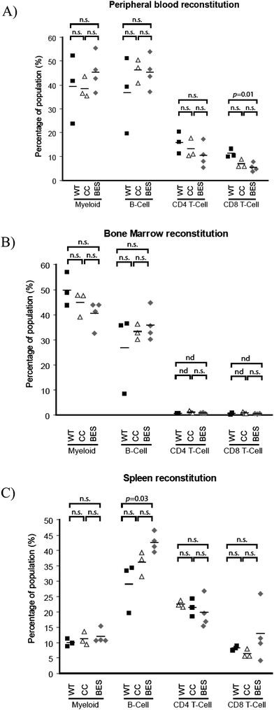 | ||
| Fig. 5 Manipulated cells were injected into irradiated mice and flow cytometry was used to analyse peripheral blood (A), bone marrow (B) and spleen cells (C) for the presence of myeloid cells (expressing CD11b on the cell surface), B cells (distinguished by B220 expression) and T cells (expressing CD3 with either CD4 or CD8 on the cell surface). CC: unmanipulated culture control, BES: bio-electrosprayed, WT: wild type mouse which has not been irradiated or received a bone marrow transplant. Horizontal bars within the graph represent the mean value for each group. Bars above the graph show statistical significance in differences between the samples encompassed by the bar. n.s. = not significant (p = >0.05), nd = not determined. | ||
As BES undergoes rigorous development, it has the potential not only to develop as a novel tissue engineering and regenerative medicinal strategy, but could also potentially undergo exploration as a possible cell diagnostic protocol. The latter is suggested by the well established cell jetting and diagnostic protocol; flow cytometry. Flow cytometry, briefly, exploits sheath flow focusing of a cell suspension into a single stream of cells. These cells subsequently pass through an interrogation chamber where, lasers assess a wide range of cellular characteristics. Viability studies on post-flow cytometered cells have demonstrated insignificant numbers of dead cells.26–28 Thus, cells that have undergone flow cytometry analysis have been used in both in vitro and in vivo experiments.29,30 Therefore, the authors see the potential for bio-electrosprays to develop as a cell analytical approach in its pursuit for exploitation in biology and medicine.
Conclusions
The ability to bio-electrospray cells and incorporate them into complex structures could be useful in many different biological and biomedical applications; from diagnostic or investigative equipment, to treatment of disease. We concentrated our study on stem cells because, depending on the source, they have the potential to produce many different cell and tissue types. Utilising bio-electrospraying to implant stem cells into a scaffold to make a three-dimensional structure is an important first step in the production of artificial tissues and organs. Here, we reinforce the fact that bio-electrospraying is not detrimental to the viability of cells, in particular progenitors of the blood system. Although this demonstrates that the cells generally remain healthy, more detailed analysis is required to ensure that less apparent damage has not been caused to the cells, which may affect their long-term survival and function. By reconstituting the blood system of lethally irradiated recipient mice and showing no significant differences in subsets of resulting cell lineages, we provide direct functional evidence for the first time that stem cells are not impaired by the bio-electrospray procedure. The cells maintain their capacity to home to the bone marrow compartment after injection into a peripheral vein, to engraft into the bone marrow space and then grow and differentiate to produce correct levels of the various cell types that make up blood.In general, there was no significant difference between wild type mice and experimental mice that have been irradiated and transplanted with control (CC) or bio-electrospray (BES) cells. In cases where there are significant differences, it is probably due to the transplantation procedure or simply biological variation seen in the relatively small groups. Importantly, no differences were observed between mice transplanted with BES cells or control cells, demonstrating that bio-electrospray has no deleterious effects on cells before or after transplantation.
These preliminary in vivo results build upon existing in vitro data and further support the application of this technology with blood stem cells and other populations such as embryonic or mesenchymal stem cells that could, in the future, be used to engineer components of the hematopoietic system as well as a range of different tissues. Consequently we are currently incorporating cells into matrices to directly form pre-organised multicellular microenvironments for possible repair or replacement of tissues and organs.
Acknowledgements
NM Wishes to gratefully acknowledge the Royal Thai Government for funding her PhD studies in the BioPhysics Group. SNJ gratefully acknowledges The Royal Society for funding this research in the BioPhysics Group at UCL. KB is funded by the Leukaemia Research Fund. We would like to thank Dr Michael Blundell with his assistance with planning and performing the in vivo experiments.References
- J. B. Fenn, M. Mann, C. K. Meng, S. F. Wong and C. M. Whitehouse, Science, 1989, 246, 64 CrossRef CAS.
- L. Larrondo and R. St.J. Manley, J. Polym. Sci.: Polym Phys., 1981, 19, 909 Search PubMed.
- S. N. Jayasinghe, Phys. E., 2006, 33, 398 CrossRef CAS.
- S. N. Jayasinghe, M. J. Edirisinghe and P. G. Kippax, Appl. Phys. A: Mater. Sci. Process., 2004, 78, 343 CrossRef CAS.
- S. N. Jayasinghe, Fullerenes, Nanotubes, Carbon Nanostruct., 2006, 14, 67 Search PubMed.
- S. N. Jayasinghe, M. J. Edirisinghe and D. Z. Wang, Nanotechnology, 2004, 15, 1519 CrossRef CAS.
- S. W. Li, S. N. Jayasinghe and M. J. Edirisinghe, Chem. Eng. Sci., 2006, 61, 3091 CrossRef CAS.
- P. Patel, S. Irvine, J. R. McEwan and S. N. Jayasinghe, Soft Matter, 2008, 4, 1219 RSC.
- S. N. Jayasinghe and A. C. Sullivan, J. Phys. Chem. B, 2006, 110, 2522 CrossRef CAS.
- J. B. Fenn, Angew. Chem., Int. Ed., 2003, 42, 3871 CrossRef CAS.
- M. R. Böhmer, R. Schroeders, J. A. M. Steenbakkers and et al, Colloids Surf., A, 2006, 289, 96 CrossRef CAS.
- O. A. Basaran, AIChE J., 2002, 48, 1842 CrossRef CAS.
- S. Arumuganathar, S. Irvine, J. R. McEwan and S. N. Jayasinghe, Biomed. Mater., 2007, 2, 158 Search PubMed.
- S. Arumuganathar, S. Irvine, J. R. McEwan and S. N. Jayasinghe, Biomed. Mater., 2007, 2, 211 Search PubMed.
- K. Nair, M. Gandhi, S. Khalil, K. C. Yan, M. Marcolongo, K. Barbee and W. Sun, Biotechnol. J., 2009, 4, 1168 Search PubMed.
- S. N. Jayasinghe, A. N. Qureshi and P. A. M. Eagles, Small, 2006, 2, 216 CrossRef CAS.
- S. N. Jayasinghe, P. A. M. Eagles and A. N. Qureshi, Biotechnol. J., 2006, 1, 86 Search PubMed.
- S. N. Jayasinghe and A. Townsend-Nicholson, Lab Chip, 2006, 6, 1086 RSC.
- A. Townsend-Nicholson and S. N. Jayasinghe, Biomacromolecules, 2006, 7, 3364 CrossRef CAS.
- J. D. W. Clark and S. N. Jayasinghe, Biomed. Mater., 2008, 3, 011001 Search PubMed.
- T. Geach, N. Mongkoldhumrongkul, L. B. Zimmerman and S. N. Jayasinghe, Analyst, 2009, 134, 743 RSC.
- S. N. Jayasinghe, S. Irvine and J. R. McEwan, Nanomedicine, 2007, 2, 555 CrossRef CAS.
- C. L. Miller, B. Dykstra and C. J. Eaves, Curr. Protoc. Immunol., 2008, 80 Search PubMed 22B.2.1.
- M. Cloupeau and B. Prunet-Foch, J. Aerosol Sci., 1994, 25, 1021 CrossRef CAS.
- D. Duft, T. Achtzehn, R. Muller, B. A. Huber and T. Leisner, Nature, 2003, 421, 128 CrossRef CAS.
- N. Ma, K. Koelling and J. J. Chalmers, Biotechnol Bioeng, 2002, 80, 428–437 CrossRef CAS 27.
- J. Pruszak, K.-C. Sonntag, M. H. Aung, R. Sanchez-Pernaute and O. Isacson, Stem Cells, 2007, 25, 2257–2268 Search PubMed.
- M. A. King, Journal of Immunological Methods, 2000, 243, 155–166 CrossRef CAS.
- S. A. Boxall, G. P. Cook, D. Pearce, D. Bonnet, Y. M. El-Sherbiny, M. P. Blundell, S. J. Howe, J. P. Leek, A. F. Markham and E. A. de Wynter, Bone Marrow Transplantation, 2009, 43, 627–635 Search PubMed.
- M. Hayashi, M. Tomida, M. Hozumi, I. C. King and A. C. Sartorelli, Leukemia Research, 1996, 20, 333–341 Search PubMed.
| This journal is © The Royal Society of Chemistry 2010 |


