Some thoughts on superhydrophobic wetting
Christian
Dorrer
and
Jürgen
Rühe
University of Freiburg, Department of Microsystems Engineering (IMTEK) and Freiburg Institute for Advanced Studies (FRIAS), Georges-Köhler-Allee 103, 79110 Freiburg. E-mail: ruehe@imtek.de; Fax: +49 761 203 7162; Tel: +49 761 203 7160
First published on 1st December 2008
Abstract
Surface roughness has a profound influence on the wetting properties of a material. This fact is especially true with respect to the wetting of superhydrophobic surfaces. As a result of a special surface structure, a drop of water brought into contact with such a material forms an almost perfect sphere and even a very slight tilting of the superhydrophobic object is sufficient to cause the drop to roll off. For the description of the behavior of drops on rough surfaces two theories, namely those of Cassie and Wenzel, are often employed. However, it is currently becoming well established that both models explain the wetting behavior more from a qualitative or practical point of view rather than giving a quantitative description. For a prediction of actual contact angles, a more complex description is required that, next to thermodynamics, takes into account the kinetics of wetting. In this article, we focus on a few key aspects of superhydrophobic wetting, namely the characterization of superhydrophobic surfaces, models for the movement of drops, transitions between the Cassie and Wenzel states, and the behavior of superhydrophobic materials under condensation.
 Christian Dorrer | Christian Dorrer holds a diploma in microsystems engineering. He recently completed his PhD work at Freiburg's Institute of Microsystems Technology, under the guidance of Prof. Jürgen Rühe. He is now with sensor company Robert-Bosch GmbH, Stuttgart. Dorrer's research interests include wetting and condensation as well as the modelling and experimental characterization of microfluidic and lab-on-a-chip systems. |
 Jürgen Rühe | In 1999, Jürgen Rühe accepted a professor position at IMTEK, University of Freiburg, where he heads the Laboratory for Chemistry and Physics of Interfaces. His research interests include the generation of tailor-made surfaces and micro- and nanostructured thin films, and the application of such surfaces in microsystems engineering, especially for chip-based bioanalytical devices. |
Introduction
The wettability, that is, how liquids behave on a surface, is one of the fundamental properties of every solid and, thus, important for a wide range of natural systems as well as in many technical applications. As far as the latter are concerned, wetting phenomena for instance play a role in the painting and coating industries or when designing windshields, waterproof clothing and other consumer products. In microengineering, surface tension effects govern the spreading of resists on silicon wafers, control glueing and soldering processes, influence the movement of liquids in microfluidic channels and lab-on-a-chip systems, and may be used for microfabrication by fluidic self-assembly.1–5From a theoretical point of view, Young's equation, formulated around 200 years ago,6 remains the fundamental equation in the science of wetting. Assuming an ideal solid surface, it relates the contact angle of a drop on a surface to the specific energies of the solid–gas, the liquid–gas, and the solid–liquid interfaces.6,7 From Young's equation, the spectrum of possible contact angles ranges from 0° (complete wetting or superwetting) to 180° (complete dewetting).
One aspect of wetting—situated at the hydrophobic extreme of the above wettability spectrum—that has recently received considerable scientific interest is superhydrophobicity (sometimes called ultrahydrophobicity).8–16 Drops that come into contact with a superhydrophobic material retain a nearly spherical shape, with the contact angles in general larger than 150° and close to 180° in some cases.8,17 A high drop mobility is a second important characteristic of a superhydrophobic surface:11,18 due to greatly decreased contact angle hysteresis, drops easily move around even if only very small forces are applied, such as by slightly tilting the substrates or blowing gently across the surfaces. Superhydrophobic properties lead to an interesting side-effect: if water drops are brought onto a superhydrophobic material as, for example, rain or by spraying, the moving drops pick up and thus remove dust and dirt particles that loosely adhere to the substrate. Such “self-cleaning” properties could be interesting for a variety of applications: examples are non-soiling clothing or wall paints, but also other self-cleaning structures such as windows or satellite dishes. Above, we have placed the term “self-cleaning” in quotation marks to point out that, in a strict view, this notation is not fully correct: as has been remarked, it is of course the water that performs the cleaning and not the surface by itself.19,20 Further applications of ultra-water-repellent materials include microfluidic systems, where superhydrophobic surfaces could for instance be used for the reduction of drag in microchannels.2,8,9,19,20
From various natural materials, superhydrophobicity has been a well-known phenomenon for thousands of years. The lotus leaf, to give just one prominent example, is a traditional symbol of purity in buddhist societies because it repels dirt and mud (Fig. 1a).21 In a pioneering study, biologists Neinhuis and Barthlott performed electron microscopy studies of the leaf, linking its water-repellent properties to the pronounced roughness of the leaf's surface and coining the term “lotus effect”.22,23 However, it is important to note that superhydrophobicity is not a curiosity resticted to the lotus leaf alone, but actually fairly common in nature: numerous other plant species exhibit similar characteristics,22–24 among them the lady's mantle (Fig. 1b). Also, many animals are equipped with superhydrophobic body parts:25–29 the Stenocara beetle, for instance, holds a structured superhydrophobic back into the Namib desert's morning wind to collect drinking water it cannot otherwise obtain in its extremely arid habitat (Fig. 1c).25 The water strider would drown pitifully were it not for its superhydrophobic legs (Fig. 1d).13 The wings of many butterflies have superhydrophobic properties because capillary forces would otherwise cause them to stick together and prevent the animals from taking to the air (Fig. 1e).29
 | ||
| Fig. 1 Natural superhydrophobic surfaces: (a) the leaf of the lotus plant, (b) the lady's mantle, (c) the Stenocara beetle, (d) the water strider and (e) butterfly wings. Reproduced with permission from ref. 49 (b), 13 (d), 29 (e). (c) is from ref. 25 and has been reprinted with permission from Macmillan Publishers Ltd. | ||
Again from the theoretical side, two parameters work together in determining the wetting properties of a material: one factor is the chemical composition of the surface, the second is the surface roughness.7,30,31 Depending on the interplay between these two characteristics, one of two distinct wetting states manifests itself: in the first case, which is frequently referred to as Wenzel wetting, drops penetrate and engulf the surface features (Fig. 2a).30 In the second case (which is termed Cassie or composite wetting), drops rest on top of the roughness features, with air trapped underneath (Fig. 2b).31 Both Wenzel's and Cassie's models as well as their application to the problems treated in this report will be discussed in detail below. Cassie wetting is often found for surfaces with hydrophobic surface chemistries and high degrees of roughness. Superhydrophobic properties (Fig. 2c) are associated exclusively with the Cassie state of wetting: in this regime, the fact that the drop's footprint is partially in contact with air leads to a balling up of the drop to a more or less spherical shape and—in many cases—an increased droplet mobility.23,32,33
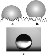 | ||
| Fig. 2 Wetting states on rough surfaces: (a) Wenzel state, (b) Cassie state, (c) drop on a superhydrophobic surface. | ||
In this report we want to review some selected aspects of the unusal wetting properties of superhydrophobic surfaces. Our short review is not intended to give an in depth overview of the vast body of literature that has been published. Rather, we want to highlight some key points which we consider interesting. After presenting some general background information on wetting, a brief classification of current synthetic strategies for the generation of artificial superhydrophobic materials is given. We then focus on the measurement of superhydrophobic contact angles and the mechanisms of drop motion in the composite state. A section is devoted to transitions between the Cassie and Wenzel wetting states, before the condensation behavior of superhydrophobic materials is finally discussed.
Theoretical background
Young's equation
Young's equation relates the thermodynamic equilibrium contact angle θY of a drop on an ideal solid to the specific energies of the solid–liquid (γsl), solid–gas (γsg) and liquid–gas (γlg) interface, where γij is a function of the chemical structure of the respective interface:6| γlgcosθY = γsg − γls | (1) |
As illustrated in Fig. 3, eqn (1) may be interpreted as an equilibrium of forces at the three-phase contact line. It is critical to note that Young's equation refers to a system in its state of thermodynamic equilibrium. Even though this condition appears trivial at first view, it is difficult to realize experimentally because non-equilibrium processes can have a rather important influence on the details of the wetting process. Evaporation, for instance, will take place even in a saturated vapor atmosphere because the vapor pressure of the liquid phase will be slightly higher than that of the gaseous phase due to the curvature of the drop's surface.34 With decreasing drop size, this problem will become more pronounced. From an oversaturated vapor, in contrast, condensation will occur. At best, non-equilibrium processes can be neglected at the time scale of the respective experiment.34 Young's equation is sometimes modified to include the effect of line tension (τ = the energy associated with a unit length of contact line) on θ:35
 | (2) |
 | ||
| Fig. 3 Drop on a surface with the contact angle θ and the interfacial energies γij indicated. | ||
Non-ideal surfaces
Eqn (1) and (2) make the assumption of an ideal solid surface, which means that roughness, chemical heterogeneity, surface reconstruction, swelling and dissolution are neglected.7,34 It was realized at an early stage that surface roughness may lead to a deviation of the contact angle from the value predicted by Young's equation.30,31 To predict the effect of this parameter, two models are commonly employed:| cosθW = rcosθY | (3) |
 | (4) |
| cosθC = ϕcosθY + ϕ − 1 | (5) |
| cosθR = rϕcosθY + ϕ − 1 | (6) |
Superhydrophobic surfaces
Most natural superhydrophobic surfaces have as a common feature that they are equipped with a multiscale surface roughness, typically a spectrum of micro- and nanostructures.23 Recent research has shown that roughness at the nanoscale plays an important role and that, for example, the lotus leaf will loose its water-repellent properties if the nanostructure is removed.48 Plants such as the Lady's mantle, which belong to a second class of natural superhydrophobic materials, rely on microscale hairs for their superhydrophobic properties.23,49 With a few exceptions,50 recent research has focused on mimicking the structure of the lotus leaf by combining hydrophobic surface chemistries with high degrees of surface roughness.8,10,13–15 Current “superhydrophobic” materials can be broadly classified into two categories: (1) surfaces with a controlled design and (2) surfaces with an arbitrary surface structure. Here, we have placed the term “superhydrophobic” in quotation marks because, as we will see in the following, it is often used in a rather loose sense and not all surfaces to which it is applied can be called superhydrophobic in the strict sense.Surfaces with a controlled design
For this type of surface, the roughness features are precisely defined, most often by lithography and silicon micromachining (Fig. 4a and b).33,42,51–57 A mask pattern is first transferred into a thin layer of photoresist that has been coated onto a silicon wafer. Subsequently, the resist is developed and the patterns are transferred into the bulk silicon by anisotropic etching. This process is frequently employed for the generation of post-like structures, where the posts are often quadratic in shape (other shapes such stars or cylinders have also been realized).51,58 Hydrophobization of the microstructures is carried out in a separate step by, for instance, depositing fluorosilanes in the form of self-assembled monolayers (SAMs).51 As an alternative, pre-synthesized fluoropolymers can be immobilized at the surfaces,55,59–61 or fluoropolymers can be grown in situ through a surface-initiated polymerization.61 The latter processes have been optimized to result in extremely hydrophobic surface coatings, with surface energies even lower than those of Teflon®.59,62 Variations of the micromachining process include using polymers as structural materials or employing various micromolding techniques.33,58,62 | ||
| Fig. 4 Man-made superhydrophobic surfaces: (a) and (b) are post-type structures, (c) is a fractal superhydrophobic surface structure obtained by the solidification of a wax melt, (d) is a superhydrophobic carbon nanotube forest, and (e) is a superhydrophobic surface obtained by the laser ablation of silicon and subsequent hydrophobization. From ref. 52 (a), 68 (c), 72 (d) and 74 (e), respectively, reproduced with permission. | ||
For purely microstructured surfaces, the hysteresis usually remains considerable (a range of 15–25° is typical);33,51,55 these materials can therefore not be called “truly” superhydrophobic, even if composite wetting is observed. Only recently has microtechnology progressed to a state where nanoscale posts with a controlled geometry could be realized.63–67 A common advantage of the surfaces discussed in this section is that, since the roughness topography is well-defined, a theoretical analysis of the wetting behavior is more readily performed.
Materials with an arbitrary surface structure
This group includes all superhydrophobic surfaces for which the roughness structure is not controlled, which means that the precise shape and location of the roughness features is statistical (Fig. 4c–e). Various topologies have been realized, from fractal to fibrous.17,68 Fabrication processes include the etching of fluoropolymer layers,69 chemical synthesis,17,70 solidification,68carbon nanotube deposition,71,72 and various other physical processes.73–76 The literature on this topic is extensive and would go beyond the scope of this report; the interested reader is referred to several recent reviews.8,10,13–16Characterization of superhydrophobic surfaces
The sessile drop method, where a small drop of liquid is placed on a surface, is currently the most popular technique for the characterization of superhydrophobic materials. The drop under analysis is observed in the side view; modern systems then employ a camera and computer for detecting the droplet shape and extracting the contact angle. The size of the drop must be chosen such that, on the one hand, the effect of evaporation on the drop shape can be neglected on the time scale of the experiment. This condition limits the minimum drop size. On the other hand, the drop must be small enough so that it is not significantly deformed due to gravitational forces. The latter point is usually considered satisfied if the drop's diameter is below the capillary length of the respective liquid.7,11 The capillary length, λC, is defined as:7 | (7) |
For the case of superhydrophobic wetting, the approximation explained in the previous paragraph breaks down: as the contact angle of a drop on a surface increases, the circular patch which forms the contact area between liquid and solid successively becomes smaller.77 The gravitational force exerted by a drop of given volume is thus concentrated onto a progressively smaller area. Ultimately, for a contact angle of 180°, the contact area would vanish and the pressure on the contact area would become infinite, which is physically not possible. Instead, the contact line is pushed outwards and the drop is deformed from the ideal spherical cap shape even for drop diameters below λC. This feature is illustrated in Fig. 5, where the shape of a drop on a superhydrophobic material (contact angle = 178°) was simulated with and without gravity acting on it. It can easily be seen that gravity leads to a significant deformation of the drop. To summarize this paragraph, the effect of gravity should not be neglected when drops on superhydrophobic surfaces are characterized.
 | ||
| Fig. 5 Surface Evolver simulation of a drop on a superhydrophobic surface (drop diameter = 2 mm, θ = 178°). For the computation of the drop shape shown in dark grey, gravity was set to zero. The shape shown in light grey was obtained by setting gravity to 9.81 m s−2. The simulation results illustrate that gravity led to a deformation of the drop base even though the drop's diameter was below the capillary length of water. | ||
From a practical point of view, several authors have recently remarked that the application of the sessile drop method is problematic when contact angles in the superhydrophobic regime are measured, even when fitting algorithms based on the Laplace–Young equation that take into account the effect of gravity on the drop shape are employed.55,78–80 At high contact angles, drops have an almost spherical shape, and the meniscus will come very close to the substrate before actually making contact at the three-phase contact line. Therefore, the region around the contact line will often appear blurred due to diffraction and scattering and, with increasing contact angle, the small slit between the meniscus and the surface will become ever more difficult to resolve. Dorrer and Rühe attributed discrepancies between theoretical models and experimental results to such problems and suggested that values obtained by the sessile drop method be treated with caution.55 As a possible alternative to the sessile drop method, Gao and McCarthy recently used a superhydrophobic surface to contact a sessile drop from above, judging the degree of superhydrophobicity by how strongly the drop was deformed as the surface was pulled away from the liquid.79 However, with respect to a quantitative measurement, this procedure in our opinion does not remove the problem from a fundamental point of view, as it just leads to an inversion of the gravitational force. We can therefore expect values similar to those obtained from the standard procedure, only with a slight over- instead of an underestimation of the contact angle. Following an approach similar to that proposed by Gao and McCarthy, de Souza et al. recently attempted a quantitative measurement by detemining the force–separation curves for capillary bridges between two parallel plates.81 Their analysis, however, did not extend into the superhydrophobic regime.
Mechanisms of superhydrophobic wetting
Cassie's theory, as it is essentially a thermodynamic model, makes no statement about hysteresis. It simply predicts an increasing “most stable” (in Marmur's notation)82 equilibrium angle with decreasing solid fraction ϕ. Experimentally, the contact angle hysteresis often tends to decrease with decreasing solid fraction but, as has also been found, drops may behave very differently on two surfaces of identical ϕ;55 thus, the solid fraction cannot be the only parameter that determines the contact angle hysteresis. Chen et al. suggested that the roughness topology plays an important part in determining the advancing and receding angles.18 These authors concluded that the contact angle hysteresis should be increased for a composite surface where the contact line comes into continuous contact with the roughness features, as is the case for a mesh-like or porous structure (Fig. 6a). For a surface consisting of isolated roughness features (e.g., posts, Fig. 6b), they assumed that the energy barriers between metastable states should be decreased, leading to a lowered hysteresis. Öner and McCarthy followed the same line of thought, highlighting the importance of “destabilizing the contact line” in order to obtain a superhydrophobic material.51 | ||
| Fig. 6 Configurations of the contact line on surfaces with different topologies (reprinted with permission from ref. 18). For surface (a), a continuous contact line can be formed, and the hysteresis will be higher than for surface (b). | ||
A quantitative prediction of the advancing and receding angles in the composite state has so far remained elusive. Early attempts were focused on deriving the contact angle hysteresis from the r and ϕ parameters, which, as discussed above, seems problematic. Miwa et al., for instance, tried to relate the sliding angle of a drop on a superhydrophobic surface to a constant k that was related to the “interaction energy” between liquid and solid.83k in turn was a function of r and ϕ. Miwa's concept was criticized by Roura and Fort, who emphasized the fact that without contact angle hysteresis, an equilibrium of drops on a tilted plane is not possible and that for this reason the advancing and receding angles must be different.84 For a spike structure that was wetted in the composite mode, these authors argued that the advancing angles are given by the Cassie equation [eqn (6)], i.e., follow from:
| cosθC.Adv = rϕcosθY + ϕ − 1 | (8) |
Assuming that the receding meniscus left behind a thin liquid film on the surface, Roura and Fort then computed the receding angle according to:
| cosθC,Rec = rϕ + ϕ − 1 | (9) |
In another attempt, McHale et al. introduced the concept of gain factors, where the gain factor described how the contact angle of a drop on a rough surface reacted to small changes in the contact angle of the smooth material, θS, around an “operating point”.85 The gain factor for the Cassie state, GC, was defined as:
 | (10) |
Unfortunately, none of the above equations [eqn (8)–(10)] has been substantiated to a sufficient degree.
Extrand recently presented a methology for the calculation of the advancing and receding angles in the Cassie state where he looked at the fraction of the contact line supported by solid, λP.78,86 He proposed the following equations:
| θC.Adv = λP(θS.Adv + ω) + (1 − λP)180∘ | (11) |
| θC,Rec = λPθS,Rec + (1 − λP)180∘ | (12) |
Many recent models for the motion of drops in the composite state remain qualitative and emphasize the importance of pinning effects. An important finding was the observation that superhydrophobic drops roll rather than slide, as Richard and Quere proved in experiments where they traced the path of a bubble that was trapped inside a drop moving over a fibrous, superhydrophobic surface (Fig. 7).88 This “rolling” mechanism of motion firstly implies that the advancing contact line is pinned on roughness edges and remains stationary while the advancing meniscus bulges forward and comes down onto neighboring roughness features from above (Fig. 8).55,78,89,90 Second, on the receding side, the meniscus is forced to lift off from the roughness features (Fig. 8). According to theoretical considerations, in contrast to the advancing motion, this step is associated with an energy barrier.55,77,91,92 The dewetting event may therefore be seen as the rate-determining step for the motion of drops in the composite state. The meniscus is likely to recede in a zipping fashion, with a dewetting front moving along the length of the contact line (Fig. 9).55 If we assume that the energy barrier for dewetting from one asperity is ΔG, then the energy barrier for dewetting from n asperities is nΔG following the mechanism illustrated in Fig. 9a, but only ΔG for the mechanism shown in Fig. 9b. Such a mechanism would agree with mechanisms of contact line motion observed for chemically heterogeneous surfaces, where it was found that it is preferable for the contact line to jump piecewise.93,94
 | ||
| Fig. 7 Trajectory of an air bubble trapped inside a drop rolling over a superhydrophobic surface (reproduced with permission from ref. 88). | ||
 | ||
| Fig. 8 Mechanism of motion of a drop on a composite surface. (a) On the receding side, the meniscus lifts off from the roughness features. This step is associated with an energy barrier ΔG. (b) On the advancing side, the meniscus comes down onto neighboring roughness features from above. | ||
 | ||
| Fig. 9 Instead of dewetting from several roughness features at once, the meniscus dewets from one asperity at a time, with a dewetting front moving along the length of the contact line (from ref. 55). | ||
Experimental data support the assumption that the receding motion dominates the movement of drops in the composite state: Morra et al. prepared superhydrophobic surfaces by submitting poly(tetrafluoroethylene) to successive oxygen plasma treatments.69 The advancing contact angles on their surfaces remained relatively independent of the duration of the treatment, while the receding angles increased with an increasing degree of roughness (Fig. 10). Dettre and Johnson's data show a similar trend.46 Gao and McCarthy prepared microposts where the post tops were smooth in the first and equipped with an additional nanostructure in the second case (Fig. 11).79 The advancing contact angles on both surfaces were identical, while differences in the receding angles were observed. Dorrer and Rühe showed that, for hydrophobicized micromachined post surfaces where the geometry was systematically varied, the advancing angles remained approximately constant.55 The receding contact angles, in contrast, were a function of the roughness geometry. In particular, the size scale of the surface had a much more prominent influence than the solid fraction (Fig. 12).
 | ||
| Fig. 10 Advancing (○) and receding (●) contact angles on plasma-etched poly(tetrafluoroethylene) as a function of treatment time. The three pairs of datapoints to the right correspond to the Cassie wetting regime. Here, the advancing angles remain constant, while the receding angles vary with the treatment time (reproduced with permission from ref. 69). | ||
 | ||
| Fig. 11 SEM image of a surface with microposts where the tops of the microposts have been coated with a hydrophobic polymer network (reproduced with permission from ref. 79). | ||
 | ||
| Fig. 12 Contact angle hysteresis on hydrophobicized silicon post surfaces as a function of the post width. The solid fractions were constant for each curve: ϕ = 25% (a), 11% (b), and 4% (c). Lines are guides to the eye. | ||
Simulations have recently shown that the base of a drop that is resting on a superhydrophobic material is strongly deformed from the ideal spherical cap shape by the underlying surface pattern.95–102 The contact line (here defined as the line in space where the meniscus leaves the plane of the composite surface; in the traditional definition, in contrast, we have multiple closed contact lines around the top of each wetted roughness feature) is strongly distorted from the circular shape and may assume different configurations depending on the position of the advancing/receding meniscus. Both features depend on the topology of the respective substrate in a complicated way. This fact implies that an analytical quantification of the advancing and receding contact angles will in general not be feasible (except for strongly simplified model geometries).46,103 However, numerical solutions should be possible, and first attempts in this direction have been made by analyzing simulated side views of the liquid–air interface of drops on various superhydrophobic materials.99,104,105
Wetting transitions
On some rough surfaces, drops in the Wenzel and Cassie states can coexist, with the actual wetting state depending on how the respective drop was deposited.12,33,53,106–108 From theory, for a given r and ϕ, the Wenzel state is energetically favored if the contact angle on the smooth material, θY, is below a critical value θCrit. θCrit follows by equating the Wenzel and the Cassie equation [eqn (3) and (6)]:109,110| rcosθCrit = ϕcosϕCrit + ϕ − 1 | (13) |
In reality, kinetic barriers may lead to a stabilization of drops in a wetting situation that is not the minimum-energy state.108,111–114 As a consequence, drops in both wetting states (Cassie and Wenzel) may appear on one and the same material. Patankar studied the Cassie-to-Wenzel transition theoretically for a model surface composed of regularly arranged posts.111 For a hydrophobic surface (i.e., θY>90°), he found the initial impalement of a drop on the post structure to be associated with an increase in interfacial energy. Energy was then recovered as the drop made contact with the bottom of the post surface and liquid–air was replaced by liquid–solid interface. Following similar considerations, Nosonovsky and Bhushan derived an energy diagram for the Cassie-to-Wenzel transition where both states were separated by an energy barrier.114
A transition of drops from the Cassie to the Wenzel state can be induced by exerting pressure on the drops,33,53,106,110 vibrating the substrate,115 applying an electrical voltage,66,67 or having droplets evaporate.114,116,117 All these methods lead to an increased Laplace pressure ΔP across the drops' liquid–air interfaces, which can thus be seen as the driving force for the transition.118 The pressure difference ΔP stems from the surface tension, γlg, and other forces such as gravity. ΔP and the radius of the meniscus are related by the Laplace equation:7
 | (14) |
A transition occurs once the meniscus is so strongly curved that either (i) direct contact with the bottom of the surface is made according to the mechanism shown in Fig. 13a or (ii) the advancing angle on the sidewalls of the roughness features is reached so that the meniscus can slide down into the structure (Fig. 13b). In drop impact experiments, Bartolo et al. recently determined the energy necessary for inducing a Cassie-to-Wenzel transition on a microstructured post surface as a function of the post height.119 For a transition according to the first mechanism, Bartolo et al. found an approximately linear increase in the energy barrier with increasing post height. Above a critical post height, the increase in the energy barrier levelled off because the transition now proceeded according to the sliding model illustrated in Fig. 13b. In a recent experimental series, the same authors investigated the shape of the drop footprint during the transition and found agreement with the model described above.116 For a similar post-type structure, Zheng et al. computed the hydraulic pressure at which a transition begins, ΔPCrit, as:120
 | (15) |
 | ||
| Fig. 13 According to the mechanism illustrated in (a), the transition from the Cassie to the Wenzel state occurs as the meniscus makes contact with the bottom of the surface while it is still pinned at the post edges. In (b), the advancing angle on the post sidewalls is reached and the meniscus slides into the structure. From ref. 119, reproduced with permission. | ||
As an important aspect, recent experimental studies and simulations indicate that the transition from the Cassie to the Wenzel state takes place not over the entire drop footprint at once, but rather proceeds starting from one or more nucleation sites (Fig. 14).94,97,115,123,124 How the transition proceeds is then determined by how easily the meniscus can move within the surface structure.
 | ||
| Fig. 14 Schematic depiction of the Cassie-to-Wenzel transition with the transition proceeding from a nucleation site at the center of the drop footprint (reproduced with permission from ref. 123). (a) Cassie, (b) intermediate, and (c) Wenzel state. | ||
While the Cassie-to-Wenzel transition has been studied extensively, the Wenzel-to-Cassie transition has received much less attention. The Cassie-to-Wenzel transition is in general assumed to be irreversible for the case where the Wenzel state is at the absolute energy minimum.105,112,113 Results reported in a recent study, however, seem to indicate that Wenzel-to-Cassie transitions are possible when the Wenzel state is metastable, and the Cassie state energetically preferred.108 It is known that the condensation of water onto microscale post-type surfaces leads to the formation of both Wenzel, Cassie, and mixed Wenzel–Cassie drops.107,108 In one series of experiments it was found that, in the course of the coalescence events that accompany such a condensation process, Wenzel drops could sometimes make a transition to the Cassie state either entirely or over part of their footprint area.108 Here, the Wenzel state was separated from the Cassie state by an energy barrier and the coalescence of two drops (that were either both mixed Cassie–Wenzel or where one was a Cassie and the other a Wenzel drop) and the concomitant elimination of liquid–air interfacial area introduced enough energy into the system for this energy barrier to be overcome.
Condensation resistance
The question of how water that is condensed onto a superhydrophobic material behaves is important for a variety of applications. It is essential to know, for instance, how water-repellent windshields respond to fogging. Breathable, waterproof clothing represents another example where superhydrophobic surfaces could be exposed to water vapor.The leaf of the lotus plant is a well-known example of a natural surface with strong superhydrophobic properties. When Cheng and Rodak condensed water onto a cooled lotus leaf, they found that the leaf's structure was penetrated by liquid (Fig. 15a); “sticky” droplets were formed.125 The leaf's superhydrophobic properties were thus lost. With respect to the practical application of superhydrophobic materials, such a scenario is of course highly undesirable since the water-repellency of the surface is lost. In contrast to Cheng and Rodak’s results, Zheng et al. recently observed that drops condensed onto a lotus leaf ended up suspended on top of the papillae that cover the leaf's surface (Fig. 15b).126
 | ||
| Fig. 15 The upper two images show the condensation of water onto a lotus leaf. (a) Cheng and Rodak observed that the leaf's structure was penetrated by liquid (reproduced with permission from ref. 125), while (b) Zheng et al. found that condensed drops ended up in the Cassie state of wetting (reused with permission from ref. 126). On microstructured post surfaces (c), condensation leads to drops that are partly in the Wenzel (indicated by arrows) and partly in the Cassie state (image reproduced with permission from ref. 107). | ||
Further systematic studies related to the condensation behavior of superhydrophobic surfaces have mainly concentrated on micromachined geometries. For this type of material, it has been found that condensation in general leads to an at least partial penetration of water into the surface structure.107,108,127–129 Narhe and Beysens found that Wenzel drops condensed onto an otherwise superhydrophobic spike structure grew following similar laws, as do drops on planar surfaces.127 For post-type surfaces, the formation of combined Cassie–Wenzel drops (i.e., drops that are partly in the Cassie and partly in the Wenzel mode) has been observed (Fig. 15c).107,108
In contrast to the purely microstructured surfaces discussed in the previous paragraph, recent research indicates that certain artificially prepared nanostructured materials may exhibit condensation-resistant properties. By condensation-resistant, we mean that condensed drops do not penetrate the surface structure, but end up in the Cassie state. Lau et al. observed that drops condensed onto superhydrophobic carbon nanotube forests retained a perfectly spherical shape.71 This property was a strong indication that the drops were in the Cassie state of wetting. Also for a surface equipped with nanotubes, Chen and coworkers reported a similar effect,130 as did other authors for a surface equipped with nanoscale silicon spikes.76 With respect to the condensation resistance of a superhydrophobic material, the size scale of the roughness features in relation to the size of the smallest stable drops is probably a critical parameter. For large surface features, condensation will at first proceed as on a smooth surface and drops in the Wenzel state will form. If, in contrast, the roughness features are on the same size scale as the smallest drops, drops will probably transition to the Cassie state at an earlier stage.
Conclusions and outlook
To summarize a few important points, the movement of drops in the superhydrophobic state is governed by how easily the meniscus can recede across the superhydrophobic surface. The receding motion can thus be seen as the rate-determining step, with the size scale and topology of the surface as the most important parameters. The drop shape and morphology of the contact line depend on the geometric and chemical properties of the respective substrate in a complicated way. Since, as a result, a quantification of the contact angle hysteresis involves the computation of a very complicated energy landscape, an analytical description of the wetting properties is possible only for extremely simplified topographies. Numerical solutions should in general be possible in particular for surfaces where the roughness is regular; however, such solutions are in turn valid only for a specific roughness geometry.While the theoretical understanding of superhydrophobic wetting has greatly improved in the past few years, three major issues remain on the agenda as far as the practical application of superhydrophobic surfaces is concerned: first, the long-term stability of superhydrophobic materials against contamination is an often overlooked, yet no less important challenge. If, for example, hydrocarbons or surface-active substances adsorb at a water-repellent surface over time, the surface energy of the material in question will increase. Once a critical surface coverage is reached, the Wenzel state will become the preferred wetting situation. This situation implies nothing less than a complete loss of the superhydrophobic properties. From a chemical point of view, the minimum surface energy that is attainable is that of a surface consisting of closest-packed CF3-moieties (such surfaces have been realized by a number of research groups). With respect to surface chemistry, it thus seems that a limit has been reached. One remaining path towards increased robustness against contamination could be the generation of oleophobic, i.e., undercut or mushroom-like structures that maintain the Cassie state of wetting even if the initial low-energy surface coating is partly covered by high-energy-contaminants.
Unfortunately, undercut and especially nanoscale structures have a low mechanical stability and are easily damaged when mechanically challenged. This feature is the second prominent problem related to the practical application of most, if not all superhydrophobic materials: as smaller and smaller (and eventually nanoscale) structures become involved, even relatively small mechanical forces may destroy the intricate surface texture and lead to a (local) destruction of the superhydrophobic properties: drops then no longer roll off but stick to the damaged areas. As far as self-cleaning is concerned, this scenario leads to a catastrophic failure, because it causes an accumulation of dirt in the damaged areas. As a possible solution to this lack of mechanical ruggedness, we could imagine materials that mimic living systems by having the ability to “heal” from damage, for instance by successively exposing fresh layers of superhydrophobic compounds upon wear. As an alternative, microstructures could be integrated into a nanostructure as protective elements that carry most of the mechanical load in tribologically demanding situations.
The third problem we want to mention here is the condensation resistance of superhydropobic surfaces, as for current materials condensation often leads to the formation of drops that are (at least partly) in the Wenzel state. Here, many aspects have remained unclear, even though first results indicate that small (that is, nanoscopic) surface size scales and certain roughness geometries (hairs and spikes) promote condensation-resistant properties.
From many model studies published in the literature, it seems that a wide spectrum of practical applications for superhydrophobic surfaces are right at the doorstep. We however have to remember that, in many of these applications, superhydrophobic materials will be exposed to harsh environmental conditions and that a number of problems still remain to be solved.
References
- S. K. Cho, K. Moon and C.-J. Kim, J. Microelectromech. Syst., 2003, 12, 70 CrossRef.
- C.-H. Choi and C.-J. Kim, Phys. Rev. Lett., 2006, 96, 06601.
- M.-H. Wu and G. M. Whitesides, J. Micromech. Microeng., 2002, 12, 747 CrossRef.
- W. Mönch and H. Zappe, J. Opt. A: Pure Appl. Opt., 2004, 6, 330 CrossRef.
- C. Dorrer, O. Prucker and J. Rühe, Adv. Mater., 2007, 19, 456 CrossRef CAS.
- T. Young, Philos. Trans. R. Soc. London, 1805, 95, 65 CrossRef.
- H.-J. Butt, K. Graf, M. Kappl, Physics and Chemistry of Interfaces, Wiley-VCH, Weinheim, 2003 Search PubMed.
- A. Nakajima, K. Hashimoto and T. Watanabe, Monatsh. Chem., 2001, 132, 31 CrossRef CAS.
- G. McHale, N. J. Shirtcliffe and M. I. Newton, Analyst, 2004, 129, 284 RSC.
- I. P. Parkin and R. G. Palgrave, J. Mater. Chem., 2005, 15, 1689 RSC.
- D. Quere, Rep. Prog. Phys., 2005, 68, 2495 CrossRef.
- M. Callies and D. Quere, Soft Matter, 2005, 1, 55 RSC.
- X. Feng and L. Jiang, Adv. Mater., 2006, 18, 3063 CrossRef CAS.
- X.-M. Li, D. Reinhoudt and M. Crego-Calama, Chem. Soc. Rev., 2007, 36, 1350 RSC.
- A. Solga, Z. Cerman, B. F. Striffler, M. Spaeth and W. Barthlott, Bioinsp. Biomim., 2007, 2, 126 Search PubMed.
- P. Roach, N. J. Shirtcliffe and M. I. Newton, Soft Matter, 2008, 4, 224 RSC.
- L. Gao and T. J. McCarthy, Langmuir, 2007, 23, 9125 CrossRef CAS.
- W. Chen, A. W. Fadeev, M. C. Hsieh, D. Öner, J. Youngblood and T. J. McCarthy, Langmuir, 1999, 15, 3395 CrossRef CAS.
- P. Gould, Mater. Today, 2003, 11, 44.
- R. Blossey, Nat. Mater., 2003, 2, 301 CrossRef CAS.
- W. E. Ward, J. Aes. Art Crit., 1952, 11, 135 Search PubMed.
- C. Neinhuis and W. Barthlott, Ann. Bot., 1997, 79, 667 CrossRef.
- W. Barthlott and C. Neinhuis, Planta, 1997, 202, 1 CrossRef CAS.
- P. Wagner, R. Fürstner, W. Barthlott and C. Neinhuis, J. Exp. Bot., 2003, 54, 1295 CrossRef CAS.
- A. R. Parker and C. R. Lawrence, Nature, 2001, 414, 33 CrossRef.
- T. Wagner, C. Neinhuis and W. Barthlott, Acta Zool., 1996, 3, 213.
- W. Lee, M. K. Jin, W. C. Yoo and J. K. Lee, Langmuir, 2004, 20, 7665 CrossRef CAS.
- X. Gao and L. Jiang, Nature, 2004, 432, 36 CrossRef CAS.
- Q. Cong, G.-H. Chen, Y. Fang and L.-Q. Ren, J. Bionics Eng., 2004, 1, 249 Search PubMed.
- R. N. Wenzel, Ind. Eng. Chem., 1936, 28, 988 CrossRef CAS.
- A. B. D. Cassie and S. Baxter, Trans. Faraday Soc., 1944, 40, 546 RSC.
- S. Herminghaus, Europhys. Lett., 2000, 52, 165 CrossRef.
- J. Bico, C. Marzolin and D. Quere, Europhys. Lett., 1999, 47, 220 CrossRef CAS.
- H.-J. Butt, D. S. Golovko and E. Bonaccurso, J. Phys. Chem. B, 2007, 111, 5277 CrossRef CAS.
- G. Wolansky and A. Marmur, Langmuir, 1998, 14, 5292 CrossRef CAS.
- T. Pompe and S. Herminghaus, Phys. Rev. Lett., 2000, 85, 1930 CrossRef CAS.
- J. Drelich, J. L. Wilbur, J. D. Miller and G. M. Whitesides, Langmuir, 1996, 12, 1913 CrossRef CAS.
- A. Marmur, J. Colloid Interface Sci., 1997, 186, 462 CrossRef CAS.
- A. Marmur, Langmuir, 2003, 19, 8343 CrossRef CAS.
- L. Gao and T. J. McCarthy, Langmuir, 2007, 23, 3762 CrossRef CAS.
- G. McHale, Langmuir, 2007, 23, 8200 CrossRef.
- M. Nosonovsky, Langmuir, 2007, 23, 9919 CrossRef.
- P. G. deGennes, Rev. Mod. Phys., 1985, 57, 827 CrossRef CAS.
- R. E. Johnson and R. H. Dettre, J. Phys. Chem., 1964, 68, 1744 CrossRef.
- J. F. Oliver, C. Huh and S. G. Mason, Colloids Surf., 1980, 1, 79 CrossRef CAS.
- R. H. Dettre and R. E. Johnson, Adv. Chem. Ser., 1964, 43, 136 CAS.
- R. H. Dettre and R. E. Johnson, Adv. Chem. Ser., 1964, 43, 112.
- Y.-T. Cheng, D. E. Rodak, C. A. Wong and C. A. Hayden, Nanotechnology, 2006, 17, 1359 CrossRef.
- A. Otten and S. Herminghaus, Langmuir, 2004, 20, 2405 CrossRef CAS.
- U. Mock, R. Förster, W. Menz and J. Rühe, J. Phys.: Condens. Matter, 2005, 17, 639.
- D. Öner and T. J. McCarthy, Langmuir, 2000, 16, 7777 CrossRef.
- Z. Yoshimitsu, A. Nakajima, T. Watanabe and K. Hashimoto, Langmuir, 2002, 18, 5818 CrossRef.
- B. He, N. A. Patankar and J. Lee, Langmuir, 2003, 19, 4999 CrossRef CAS.
- J. Jopp, H. Grüll and R. Yerushalmi-Rozen, Langmuir, 2004, 20, 10015 CrossRef CAS.
- C. Dorrer and J. Rühe, Langmuir, 2006, 22, 7652 CrossRef CAS.
- A. Shastry, M. J. Case and K. F. Böhringer, Langmuir, 2006, 22, 6161 CrossRef CAS.
- N. Anantharaju, M. V. Panchagnula, S. Vedantam, S. Neti and S. Tatic-Lucic, Langmuir, 2007, 23, 11673 CrossRef CAS.
- N. J. Shirtcliffe, S. Aquil, C. Evans, G. McHale, M. I. Newton, C. C. Perry and P. Roach, J. Micromech. Eng., 2004, 14, 1384 Search PubMed.
- J. D. S. Samuel and J. Rühe, Langmuir, 2004, 20, 10080 CrossRef CAS.
- J. D. S. Samuel, P. Ruther, H.-P. Frerichs, M. Lehmann, O. Paul and J. Rühe, Sens. Actuators, B, 2005, 110, 218 CrossRef.
- J. Pahnke and J. Rühe, Macromol. Rapid Commun., 2004, 25, 1396 CrossRef CAS.
- D.-H. Jung, I. J. Park, Y. K. Choi, S.-B. Lee, H. S. Park and J. Rühe, Langmuir, 2002, 18, 6133 CrossRef CAS.
- C. Marzolin, S. P. Smith, M. Prentiss and G. M. Whitesides, Adv. Mater., 1998, 10, 571 CrossRef CAS.
- E. Martines, K. Seunarine, H. Morgan, N. Gadegaard, C. D. W. Wilkinson and M. O. Riehle, Nano Lett., 2005, 5, 2097 CrossRef CAS.
- R. Fürstner and W. Barthlott, Langmuir, 2005, 21, 956 CrossRef.
- T. N. Krupenkin, J. A. Taylor, T. M. Schneider and S. Yang, Langmuir, 2004, 20, 3814.
- T. N. Krupenkin, J. A. Taylor, P. Kolodner and M. Hodes, AT&T Bell Laboratories Technical Journal, 2005, 10, 161 Search PubMed.
- S. Shibuichi, T. Onda, N. Satoh and K. Tsujii, J. Phys. Chem., 1996, 100, 1951.
- M. Morra, E. Occhiello and F. Garbassi, Langmuir, 1989, 5, 872 CrossRef CAS.
- M. Nicolas, F. Guittard and S. Geribaldi, Langmuir, 2006, 22, 3081 CrossRef CAS.
- K. K. S. Lau, J. Bico, K. B. K. Teo, M. Chhowalla, G. A. J. Amaratunga, W. I. Milne, G. H. McKinley and K. K. Gleason, Nano Lett., 2003, 3, 1701 CrossRef CAS.
- C. Journet, S. Moulinet, C. Ybert, S. T. Purcell and L. Bocquet, Europhys. Lett., 2005, 71, 104 CrossRef CAS.
- Y. Matsumoto and M. Ishida, Sen. Actuators, 2000, 83, 179 Search PubMed.
- T. Baldacchini, J. E. Carey, M. Zhou and E. Mazur, Langmuir, 2006, 22, 4917 CrossRef CAS.
- X. Li, Z. Cao, F. Liu, Z. Zhang and H. Dang, Chem. Lett., 2006, 35, 94 CrossRef CAS.
- C. Dorrer and J. Rühe, Adv. Mater., 2008, 20, 159 CrossRef CAS.
- L. Mahadevan and Y. Pomeau, Phys. Fluids, 1999, 11, 2449 CrossRef.
- C. W. Extrand, Langmuir, 2002, 18, 7991 CrossRef CAS.
- L. Gao and T. J. McCarthy, Langmuir, 2006, 22, 2966 CrossRef CAS.
- G. R. J. Artus, S. Jung, J. Zimmermann, H.-P. Gautschi, K. Marquardt and S. Seeger, Adv. Mater., 2006, 18, 2758 CrossRef CAS.
- E. J. de Souza, L. Gao, T. J. McCarthy, T. Arzt and A. J. Crosby, Langmuir, 2008, 24, 1391 CrossRef CAS.
- A. Marmur, Soft Matter, 2006, 2, 12 RSC.
- M. Miwa, A. Nakajima, A. Fujishima, K. Hashimoto and T. Watanabe, Langmuir, 2000, 16, 5754 CrossRef CAS.
- P. Roura and J. Fort, Langmuir, 2002, 18, 566 CrossRef CAS.
- G. McHale, N. J. Shirtcliffe and M. I. Newton, Analyst, 2004, 129, 284 RSC.
- C. W. Extrand, Langmuir, 2004, 20, 5013 CrossRef CAS.
- W. Li and A. Amirfazli, J. Colloid Interface Sci., 2005, 292, 195 CrossRef CAS.
- D. Richard and D. Quere, Europhys. Lett., 1999, 48, 286 CrossRef CAS.
- F. E. Bartell and J. W. Shepard, J. Phys. Chem., 1953, 57, 455 CrossRef CAS.
- J. P. Youngblood and T. J. McCarthy, Macromolecules, 1999, 32, 6800 CrossRef CAS.
- L. Gao and T. J. McCarthy, Langmuir, 2006, 22, 5998 CrossRef CAS.
- L. Gao and T. J. McCarthy, Langmuir, 2006, 22, 6234 CrossRef CAS.
- L. Schwartz and S. Garoff, J. Colloid Interface Sci., 1985, 106, 422 CrossRef CAS.
- L. Schwartz and S. Garoff, Langmuir, 1985, 1, 219 CrossRef CAS.
- A. Dupuis and J. M. Yeomans, Langmuir, 2005, 21, 2624 CrossRef CAS.
- A. J. Briant, A. J. Wagner and J. M. Yeomans, Phys. Rev. E, 2004, 69, 031602 CrossRef CAS.
- D. Chatain, D. Lewis, J.-P. Baland and W. C. Carter, Langmuir, 2006, 22, 4237 CrossRef CAS.
- A. Porcheron and P. A. Monson, Langmuir, 2006, 22, 1595 CrossRef.
- H. Kusumaatmaja and J. M. Yeomans, Langmuir, 2007, 23, 6019 CrossRef CAS.
- J. Hyväluoma, A. Koponen, P. Raiskinmäki and J. Timonen, Eur. Phys. J. E, 2007, 23, 289 CrossRef CAS.
- M. Lundgren, N. L. Allan and T. Cosgrove, Langmuir, 2007, 23, 1187 CrossRef CAS.
- C. Dorrer and J. Rühe, Langmuir, 2007, 23, 3179 CrossRef CAS.
- R. H. Dettre and R. E. Johnson, Adv. Chem. Ser., 1964, 43, 112.
- R. Seemann, M. Brinkmann, E. Kramer, F. Lange and R. Lipowsky, Proc. Natl. Acad. Sci. U. S. A., 2005, 102, 1848 CrossRef CAS.
- J. Zhang and D. Y. Kwok, Langmuir, 2006, 22, 4998 CrossRef CAS.
- A. Lafuma and D. Quere, Nat. Mater., 2003, 2, 457 CrossRef CAS.
- K. A. Wier and T. J. McCarthy, Langmuir, 2006, 22, 2433 CrossRef CAS.
- C. Dorrer and J. Rühe, Langmuir, 2007, 23, 3820 CrossRef CAS.
- J. Bico, U. Thiele and D. Quere, Colloids Surf., A, 2002, 206, 41 CrossRef CAS.
- D. Quere, A. Lafuma and J. Bico, Nanotechnology, 2003, 14, 1109 CrossRef CAS.
- N. A. Patankar, Langmuir, 2004, 20, 7097 CrossRef CAS.
- C. Ishino, K. Okumura and D. Quere, Europhys. Lett., 2004, 68, 419 CrossRef CAS.
- L. Barbieri, E. Wagner and P. Hoffmann, Langmuir, 2007, 23, 1723 CrossRef CAS.
- M. Nosonovsky and B. Bushan, Nanoletters, 2007, 7, 2633 CrossRef CAS.
- E. Bormashenko, R. Pogreb, G. Whyman and M. Erlich, Langmuir, 2007, 23, 6501 CrossRef CAS.
- S. Moulinet and D. Bartolo, Eur. Phys. J. E, 2007, 24, 251 CrossRef CAS.
- H. Kusumaatmaja, M. L. Blow, A. Dupuis and J. M. Yeomans, Europhys. Lett., 2008, 81, 36003 CrossRef.
- M. Reyssat, J. M. Yeomans and D. Quere, Europhys. Lett., 2008, 81, 26006 CrossRef.
- D. Bartolo, F. Bouamrirene, E. Verneuil, A. Buguin, P. Silberzan and S. Moulinet, Europhys. Lett., 2006, 74, 299 CrossRef CAS.
- Q.-S. Zheng, Y. Yu and Z.-H. Zhao, Langmuir, 2005, 21, 12207 CrossRef CAS.
- C. W. Extrand, Langmuir, 2006, 22, 1711 CrossRef CAS.
- B. Liu and F. F. Lange, J. Colloid Interface Sci., 2006, 298, 899 CrossRef CAS.
- C. Ishino and K. Okumura, Europhys. Lett., 2006, 76, 464 CrossRef CAS.
- M. Sbragaglia, A. M. Peters, C. Pirat, B. M. Borkent, R. G. H. Lammertink, M. Wessling and D. Lohse, Phys. Rev. Lett., 2007, 99, 156001 CrossRef.
- Y.-T. Cheng and D. E. Rodak, Appl. Phys. Lett., 2005, 86, 144101 CrossRef.
- Y. Zheng, D. Han, J. Zhai and L. Jiang, Appl. Phys. Lett., 2008, 92, 084106 CrossRef.
- R. D. Narhe and D. A. Beysens, Phys. Rev. Lett, 2004, 93, 076103 CrossRef CAS.
- R. D. Narhe and D. A. Beysens, Europhys. Lett., 2006, 75, 98 CrossRef CAS.
- C. C. Yung and B. Bushan, J. Microsc., 2008, 229, 127 CrossRef CAS.
- C.-H. Chen, Q. Cai, C. Tsai, C.-L. Chen, G. Xiong, Y. Yu and Z. Ren, Appl. Phys. Lett., 2007, 90, 173108 CrossRef.
| This journal is © The Royal Society of Chemistry 2009 |