Lateral cavity acoustic transducer†
Armando R.
Tovar
*a and
Abraham P.
Lee
*ab
aDepartment of Biomedical Engineering, University of California Irvine, 3120 Natural Sciences II, Irvine, CA, USA 92697-2715. E-mail: tovara@uci.edu; Fax: +01 949 824 1727; Tel: +01 949 824 9691
bDepartment of Mechanical and Aerospace Engineering, University of California Irvine, Irvine, CA, USA 92697-2715. E-mail: aplee@uci.edu; Tel: +01 949 824 9691
First published on 24th October 2008
Abstract
We present a lateral cavity acoustic transducer (LCAT) capable of pumping and mixing fluids within a microfluidic system using an acoustic energy source from an external piezoelectric buzzer. The device is capable of pumping at flow rates of approximately 250 nl min−1 and real-time mixing in low flow rate (<1 µl min−1) devices typical in microfluidic systems.
Pumping and mixing in a microfluidic system are two of the most vital functions needed to develop a truly portable microfluidic device capable of performing lab-on-a-chip (LOC) functions. Traditional pumping methods for LOC devices utilize off-chip pumps (e.g. syringe pumps) that although maintain steady low flow rates, remain large and inconsistent with the ‘microfluidic’ platform. Current microfluidic pumping technologies1 have shown some promise, yet still remain difficult to operate, fabricate and integrate into LOC systems. Microfluidic pumping technologies stem primarily from two main mechanisms for fluid actuation, mechanical and electrical. Mechanical pumps operate by displacing fluid within microchannels using a moving structure. The moving structure is actuated through mechanisms such as pneumatic,2 electromagnetic,3 and piezoelectric4activation. However, the use of mechanical actuation for fluidic pumping calls for the use of sophisticated and often costly fabrication processes to develop the device. This also makes it very difficult to develop portable devices for mass scale production and deployment. An alternative method, electrical actuation, depends on methods such as magnetohydrodynamics,5 electrohydrodynamics,6 and electrokinetics7 for fluid pumping. Although this method eliminates the need for any mechanical moving components for fluidic pumping, it has its own limitations. One main limitation of using electrical actuation for fluidic pumping is the strong correlation between pumping flow rate and pressure generation compared to the working fluid. Since electrically based fluidic actuation pumps are based on a fluid's electrical characteristics, these pumping characteristics are limited by the type of liquids and its constituents. However, low-cost and ease of fabrication make this type of pump very attractive in applications that deal with more or less purified samples.
In this communication, we demonstrate a novel method for fluidic pumping and mixing within a microfluidic system with 100 µm channels using a device termed lateral cavity acoustic transducer (LCAT). It is based on the principal of acoustic microstreaming that uses trapped air bubbles in liquid for micromixing and propulsion.8–12 The LCAT is a novel microfluidic actuator designed to carry out diverse functions such as bulk fluidic manipulation and particle trapping. The air bubbles are trapped in sidewall lateral cavities due to the liquid/air contact angle and the hydrophobic-hydrophilic interaction between the surface and liquid. These air bubbles are excited by an external acoustic field which causes the liquid/air interface to resonate. As the air/liquid interface resonates, the resulting acoustic energy energizes the bulk liquid and produces a net force perpendicular to the bubble interface and out the end of the cavity.10 The use of the lateral cavities allows for direct fluidic pumping without the use of additional objects for streamline manipulation. Alternatively, by controlling the angle of these cavities and activation frequencies, different modes of operation can be demonstrated. The cavities produce bulk fluid flow in the direction of the arrows shown in Fig. 1.
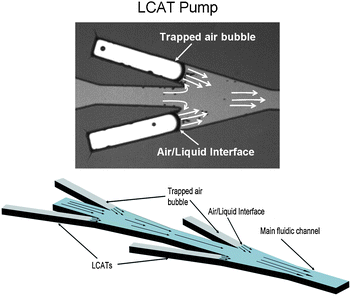 | ||
| Fig. 1 Design concept for lateral cavity acoustic transducer for pumping and mixing. The image demonstrates how the cavity orientation determines the mode of operation. | ||
The main advantage that the LCAT device has over other pumping methods is the ease of operation and fabrication. Operation of the device is done by attaching it to a piezoelectric (PZT) buzzer coated with ultrasound gel to demonstrate pumping and mixing. The pumping flow rate generated by the cavities is controlled through adjusting the amplitude and/or frequency at which the PZT is driven.
Fig. 2 shows the fabrication process for the LCAT devices similar to a process previously described in Wang et al.13 The devices are fabricated using SU-8 as the main fluidic channel carriers. A 50 µm layer of SU-8 50 is spun onto a Si wafer which is then processed to form the desired microchannels in the SU-8. This SU-8 50 layer serves as the main fluidic channel carrier for the LCAT device. A PDMS slab with inlet and outlet holes punched out is prepared to match the device layout. The PDMS slab is then O2 plasma treated for 2 min at 200 W at a pressure of 100 mTorr. Upon plasma treatment, SU-8 2 is spun on at a thickness of 2 µm and then soft baked at 90 °C for 15 min. The slab is then aligned onto the main devices so that the inlet and outlet holes match up with the microchannels. The devices are then placed on a hotplate heated to 75 °C for approximately 3 min. The SU-8 2 on the PDMS slab softens up which allows it to bond to the SU-8 50 surface of the main device. The devices are taken off the hotplate once both pieces are bonded and are then UV exposed for 30 s. After exposure, the parts are placed in a 90 °C oven for 20 min followed by a 120 °C oven for 5 min to form an irreversible bond and a completely sealed device.13
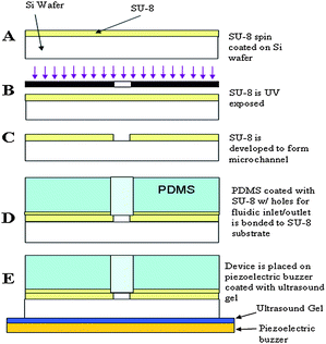 | ||
| Fig. 2 Fabrication process of LCAT devices for pumping and mixing. SU-8 50 is used as main fluidic channel carrier which is capped by a SU-8 2 coated PDMS slab. The SU-8 coated slab is bonded to the surface of the device to form an enclosed microsystem. | ||
The operation of the device is done by placing it on top of a 25 mm PZT buzzer coated with Aquasonic® 100 ultrasound transmission gel. A square-wave AC signal is generated using an Agilent 33220A function generator which is amplified at a gain of 10x using a Krohn-Hite Model 7500 amplifier. The device pumping and mixing is captured using a Photron FASTCAM that is capable of up to 10,000 frames/s attached to a Nikon Eclipse L150 upright microscope. The pumping device is filled with DI water mixed with 6 µm, non-fluorescent beads from Invitrogen (F13838) to determine the average flow rate within the channel. A drop of DI water filled with the beads is placed on the inlet of the device while a vacuum is applied at the opposite end. The vacuum is released from the part once it has filled up with the liquid. Fig. 3 shows the trapped air bubbles present after the chip is filled with fluid.
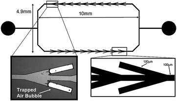 | ||
| Fig. 3 LCAT based pumping device. To demonstrate pumping within the microsystem, a rectangular design is used to show fluid movement in a counter-clockwise direction. As fluid is filled in the system, air bubbles remain trapped in the cavities shown. These trapped air bubbles are used as fluid actuators for pumping and mixing. | ||
The demonstration of the LCAT based microfluidic pump is done using a rectangular shaped recirculating design as seen in Fig. 3.† As the trapped air bubbles are activated and pumping occurs, fluid is pumped in a counter-clockwise motion around the recirculating fluid channel. Using the FASTCAM (by Photronics) and Image J, an image analysis program by NIH Image, the flow rate is estimated using the beads as markers. To test the efficiency of the LCAT based micropump, four different cavity orientations are used in which the angle, θ, (Fig. 3) is adjusted from 15° to 60°. These were chosen to determine the optimal bubble trapping angle and to determine optimal streaming conditions near the cavity outlets for maximum pumping. Fig. 4 shows the four different designs used during the testing of the LCAT pumping device. There are 20 pairs of lateral cavities with 10 pairs on each side of the rectangular shaped microsystem. Each cavity is 100 µm wide with a length of 500 µm and the main fluidic channel is 100 µm wide.
 | ||
| Fig. 4 The LCAT based pumping system is tested using 4 different cavity designs based off of varying the angle θ compared to the main fluidic channel. The lateral cavities are (A) 15°, (B) 30°, (C) 45°, and (D) 60° from the main channel. | ||
The optimal pumping frequency for the device is determined through increasing a square-wave signal from 1–60 kHz at 20 VPP and monitoring bead velocity. It is observed that multiple frequencies within this range generated pumping. In our experiments 45 kHz produced the maximum bead velocity. In using this optimal frequency, the pumping flow rate generated is controlled through adjusting the voltage amplitude at which the PZT is driven. The maximum flow rate generated in the above shown devices is approximately 250 nl min−1 with 15° angled cavities when a driving voltage of 40 Vpp and a square-wave signal of 45 kHz is applied to the PZT buzzer. Using Poiseuille's law, it is calculated that approximately 170 Pa of pressure is generated with these conditions. Fig. 5 shows the correlation of the pumping flow rate to the PZT driving voltage amplitude for each device. The pumping flow rate increases with an increase in voltage. As voltage is increased the trapped air bubble resonance becomes greater in amplitude causing it to produce a greater force out the end of the cavity. However, a point is reached in each device where the resonance amplitude of the trapped air bubble becomes so great that it becomes unstable for controlled pumping. Surface tension forces allow the bubble to remain fixed at the cavity walls, however, once the maximum amplitude is reached for the device, the bubble expands out of the cavity. As the bubble expands out of the cavity, it no longer produces a net force out the end of the cavity but rather random streaming around the bubble. Further work is being done to design a more robust system that allows pumping to occur at higher amplitudes. Specifically, work is being done to trap and control air bubbles within the microfluidic system so that bubble expansion can be controlled. In Fig. 5, the 15° angled cavity device produces the greatest flow rate while the flow rate is lower in the 30°, 45°, and 60° angled devices. The decrease in flow rate in the 30, 45°, and 60° angled cavity designs is believed to be due to the bulk force out of the cavities cancelling with one another and thus producing a lower net force than the 15° cavity designs.
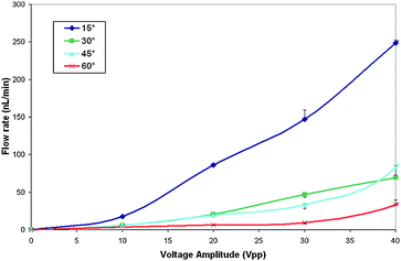 | ||
| Fig. 5 The plot shows pumping flow rate compared to the voltage supplied to the PZT. A square-wave is applied at a frequency of 45 kHz to the PZT buzzer as the voltage amplitude is increased from 0–40 Vpp. The 15° angled cavity device generated a flow rate of approximately 250 nl min−1 at 40 Vpp. Once the amplitude exceeded 40 Vpp the pumping within the system became unstable. | ||
The versatility of the LCAT device is demonstrated in a mixing device as shown in Fig. 6. In the case of the LCAT mixer, the cavities are perpendicular to the channel producing a bulk fluid movement towards the opposite sides of the channel. The cavities are designed in an alternating pattern to maximize fluid mixing within the channel as fluid flows pass the trapped air bubbles.14 The operation of the device is done by using DI water and green food coloring dye delivered via two separate inlets at 0.8 µl min−1 while the LCATs are activated from the PZT below at a frequency of 33 kHz at 35 VPP. Low Reynolds number flow keeps the streams separated until after it passes the cavities at which mixing occurs. As seen in the image, the streams become mixed upon passing through the mixing region. With the current configuration, mixing is instantaneous when the PZT is activated.
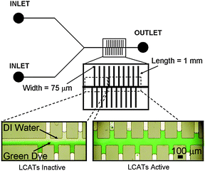 | ||
| Fig. 6 LCAT based real-time active mixer with cavities oriented perpendicular to the main fluidic channel. The design used to demonstrate mixing uses 75 µm wide cavities with lengths of 1 mm. There are ten cavities on each side of the main channel that are spaced at a distance of 150 µm apart. The main fluidic channel is 100 µm wide. The figure above shows the mixing region with the LCATs inactive and active as the fluids flow through it. | ||
In conclusion, we have developed a novel device for pumping and mixing within a microfluidic system that is simple to fabricate and operate. The present LCAT designs have shown pumping at flow rates reaching 250 nl min−1 depending on cavity orientation and driving amplitude. The robustness of the LCAT device lends itself to easy integration in a microfluidic system to provide localized pumping and fluidic control at different locations in the chip. Further improvement to the pump design may yield much higher flow rates and other modes of operation.
Acknowledgements
The authors acknowledge financial support from the DARPA S&T Program (HR0011-06-1-0050) through the Micro/nano Fluidics Fundamentals Focus (MF3) Center.References
- D. J. Laser and J. G. Santiago, J. Micromech. Microeng., 2004, 14, R35–R64 CrossRef.
- M. A. Unger, H. P. Chou, T. Thorsen, A. Scherer and S. R. Quake, Science, 2000, 288, 113–116 CrossRef CAS.
- W. Zhang and C. H. Ahn, Proc. Solid State Sensor and Actuator Workshop, 1996, 94–97 Search PubMed.
- M. C. Carrozza, N. Croce, B. Magnani and P. Dario, J. Microelectromech. Sys., 1995, 5(2), 177–179 Search PubMed.
- A. V. Lemoff and A. P. Lee, Sens. Actuators, B, 2000, 63, 178–185 CrossRef.
- A. Richter, A. Plettner and K. A. Hoffman, Sens. Actuators, A, 1991, 29, 159–168 CrossRef.
- S. Zeng, C.-H. Chen, J. C. Mikkelsen and J. G. Santiago, Sens. Actuators, B, 2001, 79(5), 107–114 CrossRef.
- S. A. Elder, J. Acoust. Soc. Am, 1959, 31(1), 54–64.
- R. H. Liu, J. Yang, M. Z. Pindera, M. Athavale and P. Grodzinski, Lab Chip, 2002, 2, 151–157 RSC.
- R. J. Dijkink, J. P. van der Dennen, C. D. Ohl and A. Prosperetti, J. Micromech. Microeng., 2006, 16, 1653–1659 CrossRef.
- J. Xu and D. Attinger, J. Micromech. Microeng., 2007, 17, 609–616 CrossRef CAS.
- P. Marmottant, J. P. Raven, H. Gardeniers, J. G. Bomer and S. Hilgenfeldt, J. Fluid Mech., 2006, 568, 109–118 Search PubMed.
- L. Wang, L. Flanagan and A. P. Lee, J. Microelectromech. Sys., 2007, 16(2), 454–461 Search PubMed.
- R. H. Liu, M. A. Stremler, K. V. Sharp, M. G. Olsen, J. G. Santiago, R. J. Adrian, H. Aref and D. J. Beebe, J. Microelectromech. Sys., 2000, 9(2), 190–197 Search PubMed.
Footnote |
| † Electronic supplementary information (ESI) available: Video of LCAT pump in Fig. 3 and pressure calculation. See DOI: 10.1039/b812435c |
| This journal is © The Royal Society of Chemistry 2009 |
