Carbon nanotube arrays and their composites for electrochemical capacitors and lithium-ion batteries
Hao
Zhang
*,
Gaoping
Cao
and
Yusheng
Yang
Research Institute of Chemical Defense, West Building, 35 Huayuanbeilu Road, Beijing, 100083, China. E-mail: dr.h.zhang@hotmail.com; Fax: +86-10-6674 8499; Tel: +86-10-6670 5840
First published on 3rd July 2009
Abstract
One of the greatest challenges for our society is to provide powerful electrochemical energy conversion and storage devices. Electrochemical capacitors and lithium-ion batteries are among the most promising candidates in terms of power- and energy-densities. The choice of electrode material is key to improving the performance of these energy conversion devices. Carbon nanotube arrays (CNTAs) and their composites show good capacity, excellent rate performance, and long cycle life when used as electrode materials because they present superior electronic conductivity, high surface area, developed porous structure, and robust properties. This review deals with recent progress in the fabrication, microstructure, and energy storage performance of different CNTA electrodes and their composites in electrochemical capacitors and lithium-ion batteries. In particular, representative examples of our CNTA-based electrodes are highlighted.
 Left to right: G. Cao, Y. Yang and H. Zhang | Hao Zhang received his PhD at the Research Institute of Chemical Defense (RICD) in 2008 under the supervision of Prof. Yusheng Yang and Prof. Gaoping Cao, working on the fabrication and application of CNTA and related materials. He is currently a staff scientist at RICD. His research interests are the synthesis and application of nanostructured materials for energy storage devices. |
Prof. Gaoping Cao got her PhD from the Tianjin University in 1998 and then joined RICD. Her current research focuses on materials and devices for energy storage and conversion. |
Yusheng Yang is a Professor at RICD and an academic of the Chinese Academy of Engineering. His recent research interests are in materials' electrochemistry with emphasis on lithium batteries, electrochemical capacitors, redox flow battery, and fuel cells. |
Broader contextIn the development of energy storage devices, nanostructured electrode materials have attracted great interest because they exhibit not only higher capacities but also better performance rates than conventional materials. Carbon nanotube arrays (CNTAs) and their composites show good capacity, excellent rate performance, and long cycle life when used as electrode materials because they present superior electronic conductivity, high surface area, developed porous structure, and robust properties. We discuss recent progress in the fabrication, microstructure, and energy storage performance of different CNTA electrodes and their composites in electrochemical capacitors and lithium-ion batteries. In particular, we highlight representative examples with results for our CNTA-based electrodes, such as polyaniline/CNTA and manganese oxide/CNTA composite electrodes. The fabrication of CNTA composites opens up a novel route for the direct synthesis of advanced functional materials for energy storage. These materials can also find applications in sensors, catalysis, and microelectronics. |
1. Introduction
Climate change, the decreasing availability of fossil fuels, and atmospheric pollution caused by combustion engines of automotive systems require a move by society towards sustainable and renewable resources.1 As a result, we are observing an increase in renewable energy production from sun and wind, as well as the development of electric vehicles or hybrid electric vehicles with low CO2 emissions. Because the sun does not shine at night, wind does not blow on command, and we expect to drive a car with at least a few hours of autonomy—energy storage systems are starting to play a larger part in our lives.1,2 In response to the needs of modern society and emerging ecological concerns, it is now essential that new, low-cost, and environmentally friendly energy conversion and storage systems are found. At the forefront of these electrochemical energy storage systems are lithium-ion batteries,3,4fuel cells,5 and electrochemical capacitors (ECs).6,7 As the performance of these devices depends intimately on the properties of their materials, considerable attention has been paid to the research and development of key materials.8–11 However, we still need to improve materials' performance substantially to meet the higher requirements of future systems, ranging from portable electronics to hybrid electric vehicles and large industrial equipment. This can be done by developing innovative materials and advancing our understanding of electrochemical interfaces at the nanoscale.1 Further breakthroughs in materials, not incremental changes, hold the key to new generations of energy storage and conversion devices.Due to their nanometre size and interesting mechanical, electrical, and optical properties, carbon nanotubes (CNTs) have, in recent years, become of great interest for many applications: batteries,12hydrogen storage,13 flat panel displays,14,15 chemical sensors,16 and ECs.17 CNTs can be divided into three categories by their wall numbers: single-walled nanotubes (SWNTs) consist of a single graphite sheet seamlessly wrapped into a cylindrical tube; double-walled nanotubes (DWNTs) or multiwalled nanotubes (MWNTs) comprise two or more such nanotubes concentrically nested like the rings of a tree trunk.18 CNT agglomerates can be divided into entangled CNTs (ECNTs) and CNT arrays (CNTAs) according to the microstructure of the agglomerates.19SEM images of an ECNT agglomerate and a CNTA agglomerate are shown in Fig. 1. It is obvious from this figure that the CNTs in the CNTA are approximately parallel with each other; contrary to this the CNTs in ECNT are twisted together. Therefore, CNTAs present a more regular pore structure, which has a profound influence on their electrochemical properties and their applications in energy storage. CNTAs are becoming increasingly important for electrochemical energy storage,20,21 which we address here. It is important to evaluate the advantages and disadvantages of CNTAs for energy conversion and storage, as well as to investigate how to control their synthesis and properties. This is the sizeable challenge facing those involved in materials research for energy conversion and storage. It is beyond the scope of this paper to give an exhaustive summary of the energy storage and conversion devices that may now or in the future benefit from the use of CNTAs; rather, we shall limit ourselves to the fields of ECs and lithium-ion batteries.
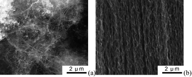 | ||
| Fig. 1 SEM images of a entangled CNT (a) and a CNT array (b). | ||
ECs, also called supercapacitors, store energy using either ion adsorption (electrochemical double layer capacitors, EDLCs) or fast surface redox reactions (pseudo-capacitors).6,22 ECs can be fully charged or discharged in seconds; as a consequence, their energy density (about 5 Wh kg−1) is lower than in batteries, but a much higher power delivery or uptake (10 kW kg−1) can be achieved for shorter times (a few seconds). ECs also present much longer cycle life (105 times) than batteries. They have had an important role in complementing or replacing batteries in the energy storage field, such as for uninterruptible power supplies (back-up supplies used to protect against power disruption) and load-levelling.23 A more recent example is the use of EDLCs in emergency doors (16 per plane) on the Airbus A380, thus proving that in terms of performance, safety and reliability ECs are definitely ready for large-scale implementation.1 A recent report by the US Department of Energy assigns equal importance to ECs and batteries for future energy storage systems,24 and the number of articles on ECs appearing in business and popular magazines show the increased interest by the general public in this topic.
EDLCs are electrochemical capacitors that store the charge electrostatically using reversible adsorption of ions of the electrolyte onto active materials that are electrochemically stable and have high accessible specific surface area (SSA). The key to obtaining high capacitance by charging the double layer is to use high SSA and electronically conducting electrodes to adsorb ions. Nanotextured graphitic carbon satisfies all the requirements for this application, including good conductivity, electrochemical stability, and open porosity. Activated, templated and carbide-derived carbons,25carbon fabrics, fibres, nanotubes, onions (single wall fullerenes, termed cages and multiwall fullerenes) and nanohorns have been tested for EDLC applications.26–28 To date activated carbons are the most widely used materials, because of their mature preparation process, high SSA, and moderate cost.
Pseudo-capacitors use fast, reversible redox reactions at the surface of active materials. Metal oxides such as RuO2, NiO, Fe3O4 or MnO2,29–31 as well as electronically conducting polymers,32 have been extensively studied in past decades. Specific pseudo-capacitance exceeds the capacitance of carbon materials using double layer charge storage. But because redox reactions are used pseudo-capacitors, like batteries, often suffer from a lack of stability during cycling. Because pseudo-capacitors store charge in the first few nanometres from the surface, decreasing the particle size increases active material usage. Therefore, the fabrication of nanoscale materials can enhance the capacitive and rate performance of pseudo-capacitors, so that just like nanomaterials, they have helped to improve lithium-ion batteries.33 Depositing pseudo-capacitive materials onto highly conductive nanocarbons to fabricate composite electrode materials is also a successful strategy for improving the cycle and rate performance of ECs.34–37
2. Carbon nanotube array electrodes for electrochemical capacitors
2.1. Fabrication of CNTA electrodes
There are two dominant routes for the fabrication of CNTA electrodes (i) transfer technique and (ii) direct growing of CNTA onto current collectors. Fig. 2 illustrates the procedures for the transfer technique.38,39 Firstly, a CNTA on silica or silicon substrates, which are the most suitable substrates for CNTA growth, was prepared by chemical vapor deposition (CVD).40–43 Secondly, the CNTA was detached from the original substrate by either cutting or other method (such as HF etching or surface tension gradient achieved by introducing hot water).44,45 Then, the pure CNTA was reattached onto arbitrary surfaces, including Ni foil, Cu foil, Al foil, stainless steel, and other current collectors, by binders (such as graphite milk),38,39 solders (such as Sn/Pb, Sn/Au, and Sn/Ag/Cu),46,47 or just surface tension,44 to fabricate CNTA electrodes. We noticed that most of the CNTA and CNTA composites reported were formed by MWNTs, not SWNTs; however, we used a SWNT-like model to construct schematic diagrams due to its simplicity. The SWNT-like CNT presented in Fig. 2 and 3, 6–8, and 11 can represent either MWNTs or SWNTs. CNTs can also be integrated onto gold surfaces by chemical bonds through a self-assembly process;48,49 however, these CNTAs may be not suitable for energy storage applications due to the complicated procedures involved in their fabrication.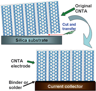 | ||
| Fig. 2 Schematic diagram of the transfer technique for CNTA electrode fabrication. | ||
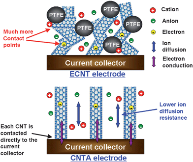 | ||
| Fig. 3 Schematic model comparing the microstructure, ion diffusion, and electron conduction in ECNT and CNTA electrodes. | ||
Compared with the transfer technique, growing CNTA directly on current collectors is more attractive and powerful due to its one-step procedure, low electric resistance between CNTA and substrate, and the formation of robust CNT–metal contacts during growth.50–53 Usually, CNTA can be grown either by using thin catalyst layers predeposited on substrates or through vapour-phase catalyst delivery. A 10–30 nm Al2O3buffer layer can effectively increase the efficiency of CNT growth by avoiding undesired chemical interaction between catalyst and substrate.40 This buffer layer also alters the catalyst–support interactions, and enhances the growth rate of CNTs.54 Our results also indicate that the properties of CNTAs are mainly determined by CVD parameters and the properties of Al2O3buffer layers,42,43,53 not by the substrates. In addition, the nonconductive Al2O3buffer layer can hardly influence the contact between the CNTA and the substrate, a result of annealing in H2 which very much affects the Al2O3 morphology, creating many holes on the Al2O3 surface,42 which ensure the contacts between the substrate and the catalyst particles trapped in these holes, and thus the contacts between the CNT grown from these catalyst particles and the substrate are established.
2.2 Electrochemical properties of CNTA electrodes and devices
CNTA electrodes store energy by the electrochemical double layer formed on the surface of each CNT in the array; thus, the cyclic voltammetry (CV) in electrolytes show rectangular shapes. Although the capacitive performance and energy storage mechanism of CNTA electrodes have been systematically studied since 2004, Martin and co-workers showed that the array-like CNT membranes present capacitive properties.20 Ajayan and coworkers grew a 400 µm long CNTA directly on a metallic alloy (Inconel 600) and showed that this electrode obtained capacitance of 18 F g−1 in 6 M KOH electrolytes.51 The CV curve of this electrode, performed at a scan rates of 1000 mV s−1, exhibited a rectangular and symmetric shape, suggesting good rate performance and low contact resistance between the CNTs and Inconel. Ajayan et al. embedded the CNTA in cellulose to fabricate an ultrathin and flexible electrode,21 which had capacitances of 35 and 22 F g−1 in 6 M KOH and an ionic liquid electrolyte, respectively. This electrode also showed capacitive properties in bioelectrolytes such as blood and sweat. Iijima and coworkers prepared a SWNT-based CNTA electrode,55 which obtained a capacitance of 80 F g−1 in 1 M Et4NBF4/PC electrolyte. Ishikawa and coworkers reported that a CNTA electrode prepared by transfer technique had capacitance of 10–15 F g−1 in organic electrolytes even at an extremely high current density of 200 A g−1,38 whereas no discharge capacitance is obtained at all with a typical high-performance activated carbon electrode at such a high current density. Iwasaki and coworkers grew 300 µm long CNTA on conductive Si substrate and showed that the CNTA obtained 83 F g−1 in organic electrolytes.56 Our group obtained a series of CNTA electrodes by both the transfer technique and direct-growing method, the experimental results show that CNTA electrodes presented 14–30 F g−1 in aqueous electrolytes, 24–83 F g−1 in organic electrolytes, and 27 F g−1 in ionic liquid.39,57,58 All CNTA electrodes show excellent rate performance.It is concluded from the results above that CNTA electrodes present higher capacitance in organic electrolytes than in aqueous electrolytes. This phenomenon has never been reported for activated carbon and other micropores (<2 nm) dominated carbon materials. CNTs normally present strong hydrophobic properties.55,57,59 Therefore, an aqueous electrolyte cannot soak the CNTA electrode thoroughly, which results in a decrease in the effective double layer surface area, and thus the decrease in specific capacitance. The hydrophilic property of CNT must be improved, which can be realized by surface treatment,60–62 to make CNTA electrodes obtain higher specific capacitances in aqueous electrolytes.
We carefully investigated the difference between the capacitive properties and energy storage characteristics of a CNTA electrode and an ECNT electrode in ionic liquid electrolytes.19 The two electrodes were both 1 mm thick and the apparent areas were same. In addition, the crystalline quality and inherent conductivity of CNTs in ECNT electrode was similar to that in the CNTA electrode. The results obtained from cyclic voltammetry, galvanostatic charge/discharge, and ac impedance showed that the CNTA electrode had higher capacitance, lower resistance, and better rate performance than the ECNT electrode. The mechanism of energy storage in both electrodes comes from the charge separation at the electrode/electrolyte interface, leading to a double layer capacitance. Theoretically, electrode material with high SSA gives high capacitance. Contrary to this, although the SSA of the ECNT electrode (283 m2 g−1) is much larger than that of the CNTA electrode (111 m2 g−1), the capacitance of the ECNT electrode is lower, which suggests that the SSA utilization of the CNTA electrode is more effective than that of the ECNT electrode.
The outer surface of CNTs mainly contributes to the surface area of these two electrodes because the inner space of CNTs is easily blocked by the bamboo-like structures of the inner graphite sheets.63 These graphite sheets curve inwards periodically to form cross walls in the CNT, just like the inner structure of a bamboo, thus the pores in CNT electrodes are formed by CNT stacking. The N2 adsorption results indicate that the pore size of the ECNT electrode shows a remarkable decrease compared to ECNT powder.19 The average pore diameters of ECNT powder and electrode are 36 and 14 nm, respectively. The reason for this pore size decrease is because the nanotubes in the ECNT electrode form bundles easily through the electrode molding process. In addition, polytetrafluoroethylene (PTFE) binder fills up the voids among nanotubes and forms large nanotube/PTFE agglomerates, which result in pore shrinkage and effective surface area loss. Although the pore size distribution (PSD) of the ECNT electrode ranges from 1.1 to 70 nm, a majority of surface area of the ECNT electrode is contributed by micropores, which are not easily penetrated by big ionic liquid ions, especially at high charge/discharge rates. On the contrary, the surface area of the CNTA electrode is mainly supplied by mesopores. Ion diffusivity plays a key factor to realize EDLCs with good power performance. As shown in Fig. 3, the ECNT electrode possesses a large ion diffusion barrier in the inner region of the electrode because of small pore size and irregular pore structure which lead to high internal resistance and inferior power performance. In contrast, CNTs in the CNTA electrode regularly align, giving an electrode with regular pore structure and large pore size. Therefore, compared to the ECNT electrode, the CNTA electrode possesses better ion diffusivity and higher capacitance.
The inherent conductivity of CNTs in CNTA and ECNT is similar; thus, the equivalent series resistance difference is mainly attributed to the electronic resistance difference related to the electrode microstructures and the ion diffusion difference. The CNTA electrode presents lower ion diffusion resistance than the ECNT electrode. Furthermore, each nanotube in the CNTA electrode is contacted directly to the current collector and the nanotubes in CNTA are much longer than that in ECNT; thus, the conductive paths in the CNTA electrode are more regular and shorter than those in the ECNT electrode. The conductive paths in the ECNT electrode form zigzags (by tens) of short CNTs. Every conductive path (from the current collector to the top of the electrode) not only is much longer than 1 mm (electrode thickness), but also contains tens of contact points. This kind of difference in conductive paths has been illustrated by Lira-Cantu and Gonzalez-Valls.64 In addition, the insulative PTFE binder further increases the resistance of the ECNT electrode. In summary, the CNTA electrode presents lower ion diffusion resistance, higher electronic conductivity, larger pores, and more regular pore structure than the ECNT electrode; thus the CNTA electrode has higher capacitance, lower resistance, and better rate performance.
It is shown that CNTA electrodes present good rate performance. We fabricated a button-like device to evaluate the power performance of CNTA-based EC. CNTAs were grown directly on Ta and stainless steel (SS) substrates by chemical vapor deposition.53 These two electrodes were used as cathode and anode to fabricate a button-like EC (see Fig. 4), 1 M Et4NBF4/PC was the electrolyte. Electrochemical performance of this CNTA-based EC is shown in Fig. 5.
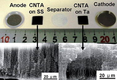 | ||
| Fig. 4 Image of CNTA electrodes used to fabricate the button-like EC. Insets are SEM images of CNTAs. | ||
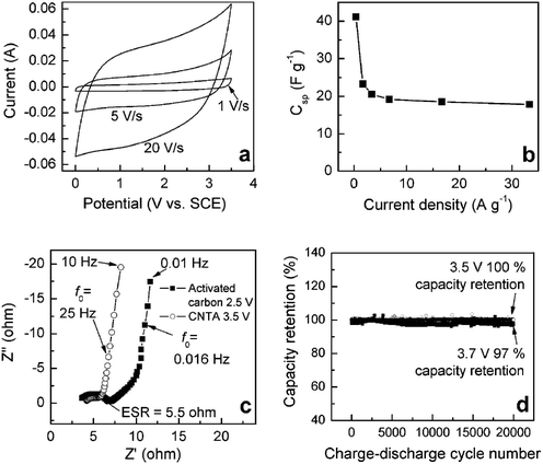 | ||
| Fig. 5 Electrochemical performance of the CNTA-based EC. (a) CV curves at various sweep rates. (b) Specific capacitance (Csp) value of the CNTA as a function of discharge current density. (c) Nyquist plots of the CNTA and activated carbon ECs. (d) Cycle test of the CNTA-based EC. | ||
The CV curves (Fig. 5a, potential ranges from 0 to 3.5 V) of the CNTA-based EC show rectangular shapes at a very high scan rate of 20 V s−1, indicating highly capacitive nature with very rapid charge/discharge characteristics.7 An impressive device property is readily realized from the CV curves. The rectangular and symmetric shape of the CV curves performed at a wide voltage window of 3.5 V, is much higher than the working voltage of activated carbon-based ECs (2.3–2.7 V) and comparable to the voltage of lithium-ion batteries, suggesting excellent stability of the CNTA electrodes. The capacitance (obtained at 0.5 A g−1) of the CNTAs is 40 F g−1. Fig. 5b shows that capacitance decreases slowly as the current density increases. As current density rises to as high as 33 A g−1, the capacitance of the CNTA is 18 F g−1, indicative of good rate performance. Nyquist plots (Fig. 5c) show that the characteristic frequencies (f0) of the CNTA-based and activated carbon-based ECs are 25 and 0.016 Hz, which shows that CNTA-based ECs present much better rate capability.65 In addition, the capacity decay of the CNTA-based EC at 25 °C was 0 and 3% of the capacitance after 20,000 cycles (Fig. 5d) at working voltages of 3.5 and 3.7 V, indicative of long cycle lives even at high working potentials. The long cycle life of the CNTA-based EC is attributed to high stability of the CNTA and the robust mechanical property of the CNTs. In summary, electrochemical performance measurements indicate that the CNTA-based EC presents high working voltage (3.5 V), long cycle life, and good rate capability. The power and energy densities are 928 kW kg−1and 69 Wh kg−1, respectively (based on the mass of CNTA), showing that CNTA-based EC is a promising candidate for power applications.
3. Carbon nanotube array composite electrodes for electrochemical capacitors
CNTA electrodes show a higher rate capability than any other EC electrode materials; however, their capacitances are moderate, i.e. 10–80 F g−1,53,56,66 which is lower than activated carbons and a lot of pseudo-capacitive materials. Pseudo-capacitive materials, such as conducting polymers and metal oxides, have high theoretical capacitance but low utilization due to their low SSA and large particle size (usually in micrometer).67 The power performance of pseudo-capacitive materials is poor due to their moderate conductivity. The cycle life of both conducting polymers and metal oxides is much shorter than carbon based materials because structure or volume change during redox reactions leads to the loss of active materials. Doping pseudo-capacitive materials into the pores of highly conductive and stable carbons is effective to improve their power and cycle performance.68–70 Considering that CNTA has regular pore structure, high SSA, homogeneous property (binder-free), and superior conductivity,39,40,42,71 depositing pseudo-capacitive materials on CNTA electrodes is a promising method for the fabrication of novel composite electrodes with superior capacitive properties (Fig. 6). Recently, researchers reported the preparation, microstructure, and capacitive properties of these CNTA-based composite materials. These novel materials can be divided into two categories: conducting polymer/CNTA electrodes and metal oxide/CNTA electrodes.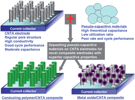 | ||
| Fig. 6 A schematic diagram illustrating how pseudo-capacitive materials may be deposited on CNTA electrodes for novel CNTA-based composite electrodes. | ||
3.1. Conducting polymer/carbon nanotube array composite materials
Conducting polymers, such as polyaniline (PANI), polypyrrole, and polythiophene have the advantages of low cost, high conductivity, high doping/dedoping rate during charge/discharge process as well as facile synthesis through chemical and electrochemical methods.72,73 Over the years much attention has been paid to synthesis of conducting polymers with high electroactive regions by controlling microstructures, and different morphologies of conducting polymers have been obtained.73–77 However, in order to further increase capacitive performance of conducting polymers, a smaller scale and hierarchically porous structure must be considered.78 Much smaller size can greatly reduce the diffusion length and ensure higher utilization of electrode materials. A hierarchically porous structure can facilitate ionic motion and enhance the rate performance of electrode.79,80 In the methods to fabricate hierarchically porous and binder-free conducting polymers-based electrodes with typical nanometer size (less than 10 nm), phase and developed conductive paths are highly desired. We realize a desired structure, i.e. a nanobrush-like PANI/CNTA composite electrode, by the combination of a CNTA framework and electrodeposition techniques.81The preparation process involves (i) growing a 35 µm high vertically-aligned CNTA on a Ta foil directly by chemical vapor deposition (CVD) at 800 °C;50 (ii) electrodepositing a 7 nm PANI nanolayer on a CNTA “template” prepared in step one by CV method.81SEM images of the PANI/CNTA composite ( left inset Fig. 7) illustrate that there are no PANI shells or agglomerates formed on the top or in the composite, indicating that the PANI deposits are well-distributed. A high resolution TEM image (right inset Fig. 7) clearly illustrates that the graphite structural CNT is covered by a uniform and compact PANI nanolayer, forming a tube-covering-tube unique microstructure. The thickness of this PANI nanolayer is only 7 nm, which is very desirable for EC applications. Moreover, the thickness of the PANI nanolayer can be controlled by electrodeposition parameters, e.g., CV sweeping cycle number (more CV cycles results in thicker PANI layers).82 The PANI nanolayer is composed of numerous nanoclusters with diameters of about 0.5 nm (see Fig. 1d), which implies that this nanolayer is composed of PANI units (0.59 × 0.44 × 0.43 nm3).83 Compared with CNTA, the PANI/CNTA composite exhibits more developed micropores (<2 nm), which can be mainly attributed to the gaps between PANI units (see right inset Fig. 7). A developed microporous structure results in the SSA of the composite (352 m2 g−1) being higher than the SSA of CNTA (201 m2 g−1). Besides micropores in the PANI nanolayer, there are a great many macropores, larger than 50 nm, in the composite nanotubes (see left inset Fig. 7). The micropores in the PANI nanolayer and the macropores between CNTs compose a hierarchical porous structure.
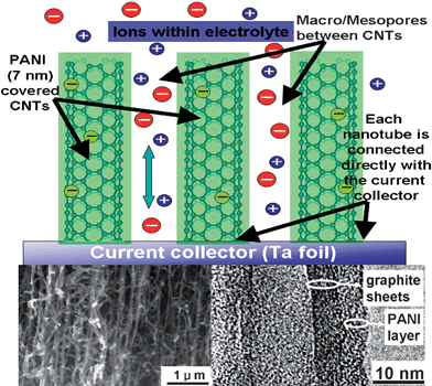 | ||
| Fig. 7 Schematic representation of the microstructure and energy storage characteristics of the PANI/CNTA composite. Left and right insets are a SEM image of a PANI/CNTA composite and a TEM image of a PANI covered CNT in the composite. | ||
The capacitance of the PANI/CNTA composite at low current density is 1030 F g−1, which is contributed by both double layer capacitance and pseudo-capacitance, is higher than other PANI materials.84 The PANI/CNTA composite still presents 978 and 789 F g−1 at current densities of as high as 118 and 294 A g−1, and the corresponding capacitance retention ratios are 95 and 77%, respectively, indicating that high capacitance can be maintained under high power operations. The capacitance loss of the composite after 5000 consecutive cycles was only 5.5%, which is the best of the conducting polymers and can be attributed to good electrochemical stability of the CNTA/Ta foil substrate in acidic solution and good mechanical properties of the CNTA support. Furthermore, the 7 nm PANI nanolayer allows for better accommodation of the large volume changes during charge/discharge without the initiation of fracture that can occur in bulk- or micron-sized materials.85 Besides acid resistance and robust property of the CNTA/Ta substrate and the 1D nanostructure of the PANI phase, PANI may form chemical bonds or other strong affinity (such as π–π stacking) with the CNT surface, which needs further investigation.86
Why the PANI/CNTA composite presents good capacitive performance is illustrated in Fig. 7. The nanometer-sized PANI layer coats every CNT in the CNTA uniformly. This geometry has several advantages. First, the PANI nanolayer is connected directly with the current collector (Ta foil) by electron “superhighways” (CNTs), thus this superior conducting network allows for efficient charge transport and enhances the electronic conductivity of the composite significantly. Second, the high SSA and nanometer size, which reduces the diffusion length of ions in the PANI phase during charge/discharge, ensure a high utilization of electrode materials, and a high specific capacity. Third, the hierarchically porous structure enhances the ionic conductivity of the PANI/CNTA composite greatly. Physicochemical properties of the electrolyte in macropores are similar to those of the bulk electrolyte with lowest resistance.87 Ion buffering reservoirs can be formed in macropores between nanotubes to minimize the diffusion distances to the interior surfaces of the PANI phase. Fourth, the use of CNTs with exceptional mechanical properties as a support and the geometry of the nanometer-size PANI layer can release the cycle degradation problems caused by mechanical problems or volume changes and can overcome nanoparticle aggregation.88,89 In addition, as the PANI phase is connected to the conducting framework, the need for binders or conducting additives, which add extra contact resistance or weight, is eliminated.
Considering that polypyrrole, polythiophene and other conducting polymers can also be prepared by electrodeposition, it is expected that these conducting polymer/CNTA composite electrodes with novel nanostructure and good capacitive performance can be prepared by electrodeposition by carefully controlling the preparation parameters. Some pioneering work in this area is reported.90,91
3.2. Metal oxide/carbon nanotube array composite materials
Like conducting polymers, metal oxides, such as NiO, Fe3O4, and MnO2 have high theoretical capacitance but low utilization ratio and poor rate performance; an exception is the noble metal oxide RuO2.1 Although RuO2 exhibits prominent capacitive properties, its high cost excludes it from wide application. Relatively low cost materials such as manganese oxides (MnOx) and nickel oxides (NiOx) can also be used as electrode materials,31 but their poor rate capability needs to be enhanced. MnOx have been thoroughly investigated because of their importance in industrial applications, such as catalysis and energy storage.92–96 Over the years various nanostructured manganese oxides, including dendritic clusters, nanocrystals with different shapes, nanowires, nanotubes, nanobelts, and nanoflowers, have been synthesized.97–104 In order to greatly increase the electrochemical performance of manganese oxides, a hierarchical porous structure with high electronic conductivity must be considered.80,81,105 Considering the successful combination of PANI and CNTA in the preparation of novel electrodes with high performance, we tried to combine the MnOx active material with CNTA frameworks, and obtained a novel nanostructured electrode with good capacitive properties.106Our strategy was to first grow a vertically-aligned CNTA on a Ta foil directly, by chemical vapor deposition at 800 °C, and then to electrodeposit manganese oxide on a CNTA “scaffold” by a potentiodynamic method. The SEM image (left inset Fig. 8) shows manganese oxide particles, around 150 nm in diameter, well dispersed on CNTA. The TEM image (right inset Fig. 8) reveals that nanostructured manganese oxide particles are composed of hundreds of surfboard-shaped nanosheets, and the nanosheets of each individual particle originate from the same core, forming a dandelion-like flower. The length and thickness of each surfboard-shaped “petal” are about 50 and 3 nm, respectively. Like the PANI/CNTA electrode, the manganese oxide particle size, distribution, and microstructure can be controlled by electrodeposition parameters, such as CV cycle number and potential range. In brief, more CV cycles and higher upper limit of the potential range result in larger manganese oxide particles and denser particle distribution, respectively, which has a profound effect on the morphology and the electrochemical properties of MnOx/CNTA composites.106
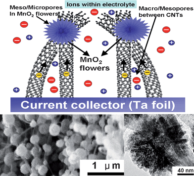 | ||
| Fig. 8 Schematic representation of the microstructure and energy storage characteristics of MnOx/CNTA composite. The left and right insets show a SEM image of MnOx/CNTA composite and TEM image of MnOx nanoflower on CNTs, respectively. | ||
The SSA of the manganese oxide nanoflower is as high as 236 m2 g−1. Compared with pure CNTA, the MnOx/CNTA composite exhibits more developed micropores, which can mainly be attributed to the numerous gaps between manganese oxide nanosheets. Besides the micropores in manganese oxide, there are a great many macropores among CNTs. The micropores in manganese oxide and the macropores between CNTs compose a hierarchically porous structure. In addition, we demonstrated that manganese oxide nanoflowers are apt to form at the junctions of CNTs,106 attributed to manganese oxide tending to nucleate at the junctions of CNTs, rather than at the curved surface of CNTs during electrodeposition. Generally, manganese oxide deposits readily form planar nanosheets on flat substrates.91,107,108 The dandelion-like nanostructure may be due to the manganese oxide deposit nucleating at the junctions of CNTs and then growing radially from the junctions. On this basis, the growth process of the MnOx/CNTA composite is different from that of the manganese oxide/nanocarbon composite, which is prepared by coating the surface of a carbon aerogel with a thin layer of manganese oxide through a self-limiting reaction.109 Details of the growth mechanism need further investigation.
Electrochemical impedance spectroscopy and CV results show that the MnOx/CNTA electrode has low equivalent series resistance, low charge-transfer resistance, and highly capacitive nature with good ion response. The composite electrode delivers a capacitance of 199 F g−1 at low current density and still retains 101 F g−1 (50.8% retention) at current density as high as 77 A g−1. To the best of our knowledge, this rate capability is the best reported for manganese oxides and their composites. In addition, the density of the composite is 1.53 g cm−3, leading to a high volumetric specific capacitance (Cv) of 305 F cm−3. The density of high surface area nanoporous carbon is around 0.5 g cm−3, with a result that the Cv is around 120 F cm−3,110,111 much lower than the Cv of MnOx/CNTA composite. The MnOx/CNTA electrode retains 97% of its capacitance after 20,000 consecutive cycles, indicative of good electrochemical stability. Good electrochemical stability is an advantage of MnOx/CNTA composites compared to conducting polymers, whose cycle lives are less than 5000 cycles.73,112
We electrodeposited manganese oxides on an ECNT electrode and an activated carbon electrode for comparison. Compared with the MnOx/ECNT composite, the MnOx/CNTA composite showed not only higher capacitance but also better rate capability,106 attributed to the fact that the MnOx deposited on ECNT is not uniform and readily forms MnOx/CNT agglomerates, resulting in worse electrochemical accessibility and lower ionic conductivity. Furthermore, the conductive paths in the ECNT electrode are inferior to that in the CNTA electrode,19 leading to lower electronic conductivity. Although the capacitance of MnOx/activated carbon is 201 F g−1, the rate performance of this composite is poor, that is, 24% capacitance retention at 10 A g−1, attributed to the low conductivity of the activated carbon substrate. On the basis of the results above, the energy storage characteristics of MnOx/CNTA composite are illustrated in Fig. 8. Manganese oxide nanoflowers are grown directly on nanostructured current collector (CNTA). This geometry has several advantages. First, each manganese oxide nanoflower is connected directly with the current collector (Ta foil) by two or more electron “superhighways” (CNTs); thus, this superior conducting network allows for efficient charge transport and enhances significantly the electronic conductivity of composite. Second, the high SSA and nanometer size, which reduces the diffusion length of ions within the manganese oxide phase during charge/discharge,73 ensures a high utilization of electrode materials and a high specific capacitance. Third, a hierarchically porous structure enhances greatly ionic conductivity of the composite. Fourth, the use of CNTs with exceptional mechanical properties as a support and the geometry of the manganese oxide nanoflower can remove the cycle degradation problems caused by mechanical problems or volume changes and can overcome nanoparticle aggregation.85,113 In addition, as every manganese oxide particle is connected to the conducting framework; the need for binders or conducting additives, which add extra contact resistance or weight, is eliminated. Thus, the MnOx/CNTA composite electrode presents the best electrochemical capacitive performance.
Broughton reported that adding acetate into a MnSO4 precursor solution can decrease the scale of MnOx deposits.114 We added 0.1 M acetate (manganese acetate) into the precursor solution for the preparation of MnOx/CNTA. The new MnOx deposits showed different morphology, i.e. flake-like deposits covering the CNTs. These MnOx flakes present higher capacitance (302 F g−1) than nanoflower-like deposits, attributed to higher SSA (322 m2 g−1). These results indicate that the microstructure and capacitive properties of MnOx/CNTA can be modified and improved by additives, such as acetates (see Fig. 9), cobalt and nickel salts. Considering that nickel oxides, cobalt oxides, magnetite, and other metal oxides can also be prepared by electrodeposition, we speculate that other metal oxide/CNTA composite electrodes with novel nanostructure and good capacitive performance can be prepared by electrodeposition with careful control of the preparation parameters. Metal oxide/CNTA composites can also be fabricated by sputtering deposition and colloidal methods.115,116
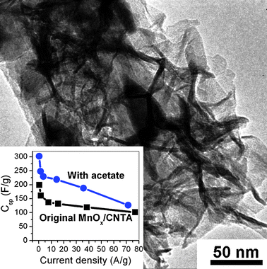 | ||
| Fig. 9 A TEM image of the MnOx/CNTA prepared by electrodeposition, adding 0.1 M acetate into the MnSO4 precursor solution. The inset shows the specific capacitances of MnOx/CNTA electrodes prepared with and without the addition of acetate. | ||
4. Carbon nanotube arrays and their composites for lithium-ion batteries
Lithium-ion batteries offer high energy density and they power most of today's portable electronic devices. Although these batteries have gained commercial success, they fall short of satisfying needs for high power and/or capacities for applications such as power tools, electric vehicles or efficient use of renewable energies.117 The limitations to capacity and power are mainly due to the low capacity and rate performance of the electrode materials. Si, SnO2, and some metal oxides, nitrides, sulfides, fluorides and phosphides show much higher capacity than commercial graphite anodes;118 however, they suffer from short cycle lives or poor reversibility because of either, the pulverization and loss of electrical contact between the active material and the current collector (Si volume changes by 400% following insertion/extraction of lithium), or the kinetics of the conversion reactions.Recently researchers reported the preparation of array-like electrode materials with superior performance. Simon and coworkers fabricated array-like electrodes formed by Fe3O4 shell/Cu-core nanowires through a two-step electrode design,119i.e. electrochemically assisted template growth of Cu nanorods onto a current collector followed by electrochemical plating of Fe3O4. These electrodes achieved good rate performance (80% retention at 8 C) and long cycle life (100 cycles). Cui and coworkers prepared a silicon nanowire array by a vapour–liquid–solid (VLS) method.120,121 This electrode had a high capacity of 3124 mAh g−1 and retained more than 3000 mAh g−1 capacity after 10 cycles, exhibiting good cycle stability.85 Ajayan and coworkers fabricated array-like electrodes formed by MnO2 shell/CNT-core nanowires by a combination of template, vacuum infiltration, and chemical vapor deposition methods.122 These electrodes showed higher capacity and better cycle performance than bulk MnO2 particles.
It is concluded that array-like electrodes formed by nanowires have several advantages for batteries: (1) to preserve the benefits of electrochemistry at nanoscale, and to achieve high rate capabilities; (2) to accommodate large strain without pulverization, and to achieve long cycle lives; (3) to provide good electronic contact and conduction, especially in nanowires with highly conductive cores (CNTs or metal nanowires). From this point of view, CNTA electrodes and their composites are promising materials for lithium-ion batteries. We studied the performance of PANI/CNTA cathodes, MnOx/CNTA cathodes, and CNTA anodes. The results indicate they have good power and cycle performance.
4.1. Lithium-ion battery cathodes using PANI/CNTA and MnOx/CNTA composites
Regarding the feasibility of using electrochemically active conducting polymers as cathode materials, the use of PANI and other redox polymers has been much hyped over the years,72,123 but development has been disappointing.3PANI films or particles have shown capacity fading and a short battery lifetime due to the loss of electrical contact between the active material and current collector, caused by shrinkage and swelling during charging (doping) and discharging (dedoping).124,125 A composite of conducting polymer with CNTs has been prepared,126,127 which has good mechanical and electrical properties, as an electrode to mitigate the degradation problem and to improve power performance; however, the improvement was limited. To further improve battery performance, an electrode of much smaller scale, ordered structure, and developed conductive paths is highly desired. Compared with ECNTs, CNTAs present a more developed meso/macropore structure and conductive paths,19 making them more powerful for the construction of electrodes.128 Our results demonstrated that the PANI/CNTA composite electrode obtained, typical nanometer scale (7 nm), had developed pore structure and conductive paths.81 This may ensure that the PANI/CNTA composite yields high performance in lithium-ion batteries.We assembled a nanostructured PANI/CNTA electrode into a lithium-ion battery for testing. The observed capacity (98 mAh g−1) of the PANI/CNTA composite was higher than that of the original CNTA and PANI/ECNT composite.127 Even at the 10 C rate, the capacity remained more than 70 mAh g−1, which is a much better rate performance than that of PANI/ECNT. Significantly, PANI/CNTA had 54 and 48 mAh g−1 at 60 and 260 C rates, respectively, demonstrating that half of the capacity can be delivered within 14 s, which is comparable to LiFePO4-based ultrafast discharging materials and highly desirable for use in HEVs.129 The good power performance of the PANI/CNTA electrode is mainly attributed to its nanostructure, i.e., the nanometer-sized PANI layer coats every CNT in a CNTA uniformly. The PANI nanolayer is connected directly with the current collector (Ta foil) by electron “superhighways” (CNTs); this superior conducting network allows for efficient charge transport and enhances the electronic conductivity of the composite significantly. In addition, the nanometer size, which reduces the diffusion length of ions in the PANI phase during the charge/discharge process, then ensures a high utilization of electrode materials even at high rates. The cyclability of the PANI/CNTA electrode at high rates was also good. Using the 10 C rate, the capacity loss after 100 cycles was 20%, mainly attributed to the use of a CNTA with exceptional mechanical properties as a support. Furthermore, the 7 nm scale PANI nanolayer allowed for better accommodation of the large volume changes occurring during charge/discharge, without the initiation of fracture that can occur in bulk or micrometer-sized materials.85 During the cycling process, the coulombic efficiency (discharge capacity/charge capacity) remained at 100% from the second cycle, due to the high utilization efficiency of PANI. This is because the 7 nm scale PANI nanolayer is readily penetrated by the electrolyte. The 79% coulombic efficiency of the first cycle is mainly attributed to the irreversible reaction during the first doping/dedoping.127
Despite the great potential of manganese oxide-based cathodes,130–134 their utilization in batteries has been plagued by problems of moderate capacity and poor stability. We assembled a nanostructured MnOx/CNTA electrode into a lithium-ion battery for testing. Discharge profiles at various rates for MnOx/CNTA cathodes are shown in Fig. 10. The capacity (246 mAh g−1) of the MnOx/CNTA composite at low rate (0.4 C) was comparable to other MnOx-based nanostructures. Surprisingly, MnOx/CNTA had 51 and 42 mAh g−1 at 50 and 60 C rates, respectively, much better than other MnOx-based cathodes. It is concluded that the CNTA framework can enhance the rate performance of electrode materials by providing good electronic conduction paths and preserving the benefits of electrochemistry at the nanoscale. CNTA can also accommodate large strain during charge/discharge without pulverization, so ensuring good cycle performance. Therefore, depositing other cathode materials, such as LiCoO2 and LiFePO4, onto CNTA substrates is promising for the fabrication of novel cathodes with good power and cycle performances
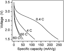 | ||
| Fig. 10 Discharge profiles at various rates for MnOx/CNTA cathodes. | ||
4.2. Lithium-ion battery anodes using CNTA electrodes
CNTs prepared by various synthesis conditions and treatments have exhibited reversible capacities of 80–640 mAh g−1 as anodes.12,20,135–141 However, the rate performance and cycle stability of CNTs is not satisfactory, this may be attributed to the fact that CNT electrodes considered in all of these reports fall short of superior conductive paths. Considering that array-like electrodes have exhibited higher capacity, better rate and cycle performance than electrodes formed by disordered nanowires or nanoparticles,85,119CNTA electrodes are promising for anodes.142 We therefore studied the performance of CNTA anodes in lithium-ion batteries. Electrochemical experiments were performed using Swagelok-type cells, whose main features are shown in Fig. 11. Fig. 11 presents the results of galvanostatic charge/discharge on the CNTA electrode. The CNTA anode had a reversible capacity of 200 mAh g−1, which is lower than commercial graphite because inner graphitic layers of CNTs in CNTA cannot be penetrated by lithium ions, this is demonstrated by TEM results. Although the capacity of the CNTA anode is moderate, its rate and cycle performance is good. The CNTA anode exhibits 75 and 24 mAh g−1 at high discharge rates of 36 and 600 C, which is superior to ECNT electrodes and can be attributed to its highly conductive nanostructures. The CNTA anode can retain more than half of its capacity after 2000 cycles at high rates. SEM results showed that the CNTA electrodes retain its array-like structure after 2000 lithium ion insertion/removal reactions, demonstrating its robust mechanical properties. TEM results showed that only the top opening and the outer shells of the CNTs in the array are expanded by lithium ion insertion, the graphitic layer structure of the inner shells is retained, indicating that most of the developed conductive paths in the original CNTA electrode are retained. Therefore, depositing other high capacity anode materials, such as Si and SnO2, onto CNTA substrates is promising for the fabrication of novel anodes with both high power and high energy as well as good cycle performances.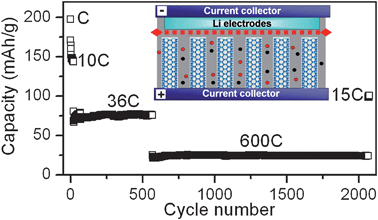 | ||
| Fig. 11 Capacities at various rates and cycle performances of a CNTA anode in a lithium-ion battery. Inset: Schematic diagram showing the structure of the device with a CNTA anode. | ||
5. Conclusions
This work provides a brief overview of the most recent research developments in the fabrication and application of CNTAs and their composites as electrodes in ECs and lithium-ion batteries. CNTA electrodes show excellent power performance and long cycle life for EC electrodes and anodes of lithium-ion batteries. They exhibit good future potential for high power devices; however, the moderate capacity limits their applications. The regular pore structure, high SSA, robust mechanical properties, high conductivity, homogeneous properties (binder free), and chemical stability make CNTA electrodes perfect substrates for depositing electroactive materials. PANI/CNTA and MnOx/CNTA composite electrodes with hierarchical porous structure, high SSA, and excellent conductivity present high energy and power densities as well as long cycle life as cathodes for both ECs and lithium-ion batteries. The fabrication of CNTA composites opens up a novel route for the direct synthesis of advanced functional materials for energy storage. We speculate that other high capacity or electroactive materials, such as Si, SnO2, LiFePO4, Pt could be deposited on highly conductive CNTA substrates for novel composite electrodes. These materials would find applications in, not only energy storage, but also sensors, catalysis, and microelectronics.Although many different synthesis techniques can be applied for the synthesis of CNTA electrodes, few are promising candidates for low cost and mass production. Nevertheless, reproducibility of the alignment and dimensions of these nanostructures has not been fully accomplished. A synthesis technique that is able to control the synthesis of CNTA electrodes is required, and will be a precondition for mass application of CNTA-based materials.
Acknowledgements
This work was financial supported by National Natural Science Foundation of China (20633040). We thank Prof. Zhennan Gu, Prof. Zujin Shi, and Dr Zhiyong Wang (Peking University) for their valuable help.References
- P. Simon and Y. Gogotsi, Nat. Mater., 2008, 7, 845 CrossRef CAS.
- J. Tollefson, Nature, 2008, 456, 436 CrossRef CAS.
- M. Armand and J. M. Tarascon, Nature, 2008, 451, 652 CrossRef CAS.
- Y. Wang and G. Cao, Adv. Mater., 2008, 20, 2251 CrossRef CAS.
- B. Sorensen, Hydrogen and Fuel Cells, Elsevier Academic Press, London, 2005 Search PubMed.
- B. E. Conway, Electrochemical Supercapacitors: Scientific Fundamentals and Technological Applications, Kluwer Academic Publishers/Plenum Press, New York, 1999 Search PubMed.
- R. Kötz and M. Carlen, Electrochim. Acta, 2000, 45, 2483 CrossRef CAS.
- K. Kang, Y. S. Meng, J. Bréger, C. Grey and G. Ceder, Science, 2006, 311, 977 CrossRef CAS.
- Y. S. Hu, Y. G. Guo, W. Sigle, S. Hore, P. Balaya and J. Maier, Nat. Mater., 2006, 5, 713 CrossRef CAS.
- D. Choi, G. E. Blomgren and P. N. Kumta, Adv. Mater., 2006, 18, 1178 CrossRef CAS.
- E. Frackowiak, Phys. Chem. Chem. Phys., 2007, 9, 1774 RSC.
- E. Frackowiak, S. Gautier, H. Gaucher, S. Bonnamy and F. Beguin, Carbon, 1999, 37, 61 CrossRef.
- A. C. Dillon, K. M. Jones, T. A. Bekkedahl, C. H. Kiang, D. S. Bethune and M. J. Heben, Nature, 1997, 386, 377 CrossRef CAS.
- J. Wildoer, L. Venema, A. Rinzler, R. E. Smalley and C. Dekker, Nature, 1998, 391, 59 CrossRef CAS.
- Z. F. Ren, Z. P. Huang, J. W. Xu, J. H. Wang, P. Bush, M. P. Siegal and P. N. Provencio, Science, 1998, 282, 1105 CrossRef CAS.
- J. Kong, N. R. Franklin, C. Zhou, M. G. Chapline, S. Peng, K. Cho and H. J. Dai, Science, 2000, 287, 622 CrossRef CAS.
- R. Baughman, A. Zakhidov and W. de Heer, Science, 2002, 297, 787 CrossRef CAS.
- P. M. Ajayan, Chem. Rev., 1999, 99, 1787 CrossRef CAS.
- H. Zhang, G. P. Cao, Y. S. Yang and Z. N. Gu, J. Electrochem. Soc., 2008, 155, K19 CrossRef CAS.
- G. Che, B. B. Lakshmi, E. R. Fisher and C. R. Martin, Nature, 1998, 393, 346 CrossRef CAS.
- V. L. Pushparaj, M. M. Shaijumon, A. Kumar, S. Murugesan, L. Ci, R. Vajtai, R. J. Linhardt, O. Nalamasu and P. M. Ajayan, Proc. Natl. Acad. Sci. U. S. A., 2007, 104, 13574 CrossRef.
- M. Winter and R. J. Brodd, Chem. Rev., 2004, 104, 4245 CrossRef CAS.
- J. R. Miller and P. Simon, Science, 2008, 321, 651 CrossRef CAS.
- US Department of Energy. Basic Research Needs for Electrical Energy Storage. Data from http://www.sc.doe.gov/bes/reports/abstracts.html%23EES2007, 2007 Search PubMed.
- A. Jänes, T. Thomberg and E. Lust, Carbon, 2007, 45, 2717 CrossRef CAS.
- C. Portet, J. Chmiola, Y. Gogotsi, S. Park and K. Lian, Electrochim. Acta, 2008, 53, 7675 CrossRef CAS.
- C. M. Yang, Y. J. Kim, M. Endo, H. Kanoh, M. Yudasaka, S. Iijima and K. Kaneko, J. Am. Chem. Soc., 2007, 129, 20 CrossRef CAS.
- A. G. Pandolfo and A. F. Hollenkamp, J. Power Sources, 2006, 157, 11 CrossRef CAS.
- N. L. Wu, Mater. Chem. Phys., 2002, 75, 6 CrossRef CAS.
- T. Brousse, M. Toupin, R. Dugas, L. Athouël, O. Crosnier and D. Bélanger, J. Electrochem. Soc., 2006, 153, A2171 CrossRef CAS.
- J. Cheng, G. P. Cao and Y. S. Yang, J. Power Sources, 2006, 159, 734 CrossRef CAS.
- A. Rudge, I. Raistrick, S. Gottesfeld and J. P. Ferraris, J. Power Sources, 1994, 47, 89 CrossRef CAS.
- A. S. Arico, P. Bruce, B. Scrosati, J. M. Tarascon and W. V. Schalkwijk, Nat. Mater., 2005, 4, 366 CrossRef CAS.
- C. Wan, K. Azumi and H. Konno, Electrochim. Acta, 2007, 52, 3061 CrossRef CAS.
- A. K. Cuentas-Gallegos, R. Martínez-Rosales, M. Baibarac, P. Gómez-Romero and M. E. Rincón, Electrochem. Commun., 2007, 9, 2088 CrossRef CAS.
- S. L. Kuo and N. L. Wu, J. Power Sources, 2006, 162, 1437 CrossRef CAS.
- W. Liu, Y. Soneda, M. Kodama, J. Yamashita and H. Hatori, Carbon, 2007, 45, 2759 CrossRef CAS.
- Y. Honda, T. Haramoto, M. Takeshige, H. Shiozaki, T. Kitamura and M. Ishikawa, Electrochem. Solid-State Lett., 2007, 10, A106 CrossRef CAS.
- H. Zhang, G. P. Cao and Y. S. Yang, Nanotechnology, 2007, 18, 195607 CrossRef.
- K. Hata, D. N. Futaba, K. Mizuno, T. Namai, M. Yumura and S. Iijima, Science, 2004, 306, 1362 CrossRef CAS.
- G. Y. Xiong, D. Z. Wang and Z. F. Ren, Carbon, 2006, 44, 969 CrossRef CAS.
- H. Zhang, G. P. Cao, Z. Y. Wang, Y. S. Yang, Z. J. Shi and Z. N. Gu, J. Phys. Chem. C, 2008, 112, 4524 CrossRef CAS.
- H. Zhang, G. P. Cao, Z. Y. Wang, Y. S. Yang, Z. J. Shi and Z. N. Gu, J. Phys. Chem. C, 2008, 112, 12706 CrossRef CAS.
- G. Y. Zhang, D. Mann, L. Zhang, A. Javey, Y. M. Li, E. Yenilmez, Q. Wang, J. P. McVittie, Y. Nishi, J. Gibbons and H. J. Dai, Proc. Natl. Acad. Sci. U. S. A., 2005, 102, 16141 CrossRef CAS.
- Y. Murakami and S. Maruyama, Chem. Phys. Lett., 2006, 422, 575 CrossRef CAS.
- L. B. Zhu, Y. Y. Sun, D. W. Hess and C. P. Wong, Nano Lett., 2006, 6, 243 CrossRef CAS.
- A. Kumar, V. L. Pushparaj, S. Kar, O. Nalamasu and P. M. Ajayan, Appl. Phys. Lett., 2006, 89, 163120 CrossRef.
- J. Yu, J. G. Shapter, M. R. Johnston, J. S. Quinton and J. J. Gooding, Electrochim. Acta, 2007, 52, 6206 CrossRef CAS.
- D. Nkosi and K. I. Ozoemena, Electrochim. Acta, 2008, 53, 2782 CrossRef CAS.
- T. Hiraoka, T. Yamada, K. Hata, D. N. Futaba, H. Kurachi, S. Uemura, M. Yumura and S. Iijima, J. Am. Chem. Soc., 2006, 128, 13338 CrossRef CAS.
- S. Talapatra, S. Kar, S. K. Pal, R. Vajtai, L. Ci, P. Victor, M. M. Shaijumon, S. Kaur, O. Nalamasu and P. M. Ajayan, Nat. Nanotechnol., 2006, 1, 112 Search PubMed.
- R. Signorelli, J. Schindall and J. Kassakian, Proc. 14th Int. Seminar on Double Layer Capacitors and Similar Energy Storage Devices, Florida, 2004 Search PubMed.
- H. Zhang, G. P. Cao, Z. Y. Wang, Y. S. Yang and Z. N. Gu, Carbon, 2008, 46, 822 CrossRef CAS.
- T. Iwasaki, G. Zhong, T. Aikawa, T. Yoshida and H. Kawarada, J. Phys. Chem. B, 2005, 109, 19556 CrossRef CAS.
- D. N. Futaba, K. Hata, T. Yamada, T. Hiraoka, Y. Hayamizu, Y. Kakudate, O. Tanaike, H. Hatori, M. Yumura and S. Iijima, Nat. Mater., 2006, 5, 987 CrossRef CAS.
- T. Iwasaki, T. Maki, D. Yokoyama, H. Kumagai, Y. Hashimoto, T. Asari and H. Kawarada, Phys. Status Solidi, 2008, 2, 53 Search PubMed.
- H. Zhang, G. P. Cao and Y. S. Yang, J. Power Sources, 2007, 172, 476 CrossRef CAS.
- H. Zhang, G. P. Cao, Y. S. Yang and Z. N. Gu, Carbon, 2008, 46, 30 CrossRef CAS.
- S. Musso, S. Porro, M. Giorcelli, A. Chiodoni, C. Ricciardi and A. Tagliaferro, Carbon, 2007, 45, 1133 CrossRef CAS.
- B. Yoon, S. Jeong, K. Lee, H. Kim, C. Park and J. Han, Chem. Phys. Lett., 2004, 388, 170 CrossRef CAS.
- P. Li, X. Lim, Y. Zhu, T. Yu, C. K. Ong, Z. Shen, A. T. Wee and C. H. Sow, J. Phys. Chem. B, 2007, 111, 1672 CrossRef CAS.
- L. Ci, R. Vajtai and P. M. Ajayan, J. Phys. Chem. C, 2007, 111, 9077 CrossRef CAS.
- P. Ayala, A. Grüneis, T. Gemming, B. Büchner, M. H. Rümmeli, D. Grimm, J. Schumann, R. Kaltofen, F. L. Freire Jr., H. D. Fonseca Filho and T. Pichler, Chem. Mater., 2007, 19, 6131 CrossRef CAS.
- I. Gonzalez-Valls and M. Lira-Cantu, Energy Environ. Sci., 2009, 2, 19 RSC.
- P. Taberna, P. Simon and J. Fauvarque, J. Electrochem. Soc., 2003, 150, A292 CrossRef CAS.
- L. J. Gao, A. P. Peng, Z. Y. Wang, H. Zhang, Z. J. Shi, Z. N. Gu, G. P. Cao and B. Z. Ding, Solid State Commun., 2008, 146, 380 CrossRef CAS.
- X. H. Yang, Y. G. Wang, H. M. Xiong and Y. Y. Xia, Electrochim. Acta, 2007, 53, 752 CrossRef CAS.
- T. Fukushima, A. Kosaka, Y. Yamamoto, T. Aimiya, S. Notazawa, T. Takigawa, T. Inabe and T. Aida, Small, 2006, 2, 554 CrossRef CAS.
- V. Subramanian, H. Zhu and B. Wei, Electrochem. Commun., 2006, 8, 827 CrossRef CAS.
- E. Frackowiak and F. Béguin, Carbon, 2001, 39, 937 CrossRef CAS.
- D. Zilli, P. R. Bonelli and A. L. Cukierman, Nanotechnology, 2006, 17, 5136 CrossRef.
- P. Novák, K. Müller, K. S. V. Santhanam and O. Haas, Chem. Rev., 1997, 97, 207 CrossRef CAS.
- Y. G. Wang, H. Q. Li and Y. Y. Xia, Adv. Mater., 2006, 18, 2619 CrossRef CAS.
- H. J. Qiu, J. Zhai, S. H. Li and M. X. Wan, Adv. Funct. Mater., 2003, 13, 925 CrossRef CAS.
- J. X. Huang and R. B. Kaner, J. Am. Chem. Soc., 2004, 126, 851 CrossRef CAS.
- V. Gupta and N. Miura, Electrochem. Commun., 2005, 7, 995 CrossRef CAS.
- Z. X. Wei and M. X. Wan, Adv. Mater., 2002, 14, 1314 CrossRef CAS.
- L. Liang, J. Liu, C. F. Windisch, G. J. Exarhos and Y. Li, Angew. Chem., Int. Ed., 2002, 41, 3665 CrossRef CAS.
- E. S. Toberer, T. D. Schladt and R. Seshadri, J. Am. Chem. Soc., 2006, 128, 1462 CrossRef CAS.
- D. W. Wang, F. Li, M. Liu, G. Q. Lu and H. M. Cheng, Angew. Chem., Int. Ed., 2008, 47, 373 CrossRef CAS.
- H. Zhang, G. P. Cao, Z. Y. Wang, Y. S. Yang, Z. J. Shi and Z. N. Gu, Electrochem. Commun., 2008, 10, 1056 CrossRef CAS.
- H. Zhang, G. P. Cao, W. K. Wang, K. G. Yuan, B. Xu, W. F. Zhang, J. Cheng and Y. S. Yang, Electrochim. Acta, 2009, 54, 1153 CrossRef CAS.
- M. J. Winokur and B. R. Mattes, Macromolecules, 1998, 13, 8183 CrossRef.
- C. C. Hu and J. Y. Lin, Electrochim. Acta, 2002, 47, 4055 CrossRef CAS.
- C. K. Chan, H. L. Peng, G. Liu, K. McIlwrath, X. F. Zhang, R. A. Huggins and Y. Cui, Nat. Nanotechnol., 2008, 3, 31 Search PubMed.
- D. Tasis, N. Tagmatarchis, A. Bianco and M. Prato, Chem. Rev., 2006, 106, 1105 CrossRef CAS.
- D. R. Rolison, Science, 2003, 299, 1698 CrossRef CAS.
- M. Hughes, M. Shaffer, N. C. Renouf, C. Singh, G. Z. Chen, D. J. Fray and A. H. Windle, Adv. Mater., 2002, 14, 382 CrossRef CAS.
- E. Frackowiak, V. Khomenko, K. Jurewicz, K. Lota and F. Béguin, J. Power Sources, 2006, 153, 413 CrossRef CAS.
- J. H. Chen, Z. P. Huang, D. Z. Wang, S. X. Yang, W. Z. Li, J. G. Wen and Z. F. Ren, Synth. Met., 2001, 125, 289 CrossRef.
- S. I. Cho and S. B. Lee, Acc. Chem. Res., 2008, 41, 699 CrossRef CAS.
- J. Kim and A. Manthiram, Nature, 1997, 390, 265 CrossRef CAS.
- J. W. Long, C. P. Rhodes, A. L. Young and D. R. Rolison, Nano Lett., 2003, 3, 1155 CrossRef CAS.
- Y. Murakami and K. Konishi, J. Am. Chem. Soc., 2007, 129, 14401 CrossRef CAS.
- S. Zhu, H. Zhou, M. Hibino, I. Honma and M. Ichihara, Adv. Funct. Mater., 2005, 15, 381 CrossRef CAS.
- X. F. Shen, Y. S. Ding, J. Liu, J. Cai, K. Laubernds, R. P. Zerger, A. Vasiliev, M. Aindow and S. L. Suib, Adv. Mater., 2005, 17, 805 CrossRef CAS.
- J. K. Yuan, W. N. Li, S. Gomez and S. L. Suib, J. Am. Chem. Soc., 2005, 127, 14184 CrossRef CAS.
- M. Yin and S. O'Brien, J. Am. Chem. Soc., 2003, 125, 10180 CrossRef CAS.
- X. H. Zhong, R. G. Xie, L. T. Sun, I. Lieberwirth and W. J. Knoll, J. Phys. Chem. B, 2006, 110, 2 CrossRef CAS.
- L. C. Zhang, Z. H. Liu, H. Lv, X. H. Tang and K. Ooi, J. Phys. Chem. C, 2007, 111, 8418 CrossRef CAS.
- M. S. Wu, P. J. Chiang, J. T. Lee and J. C. Lin, J. Phys. Chem. B, 2005, 109, 23279 CrossRef CAS.
- F. Y. Cheng, J. Chen, X. L. Gou and P. W. Shen, Adv. Mater., 2005, 17, 2753 CrossRef CAS.
- V. Subramanian, H. W. Zhu, R. Vajtai, P. M. Ajayan and B. Q. Wei, J. Phys. Chem. B, 2005, 109, 20207 CrossRef CAS.
- Y. Oaki and H. Imai, Angew. Chem., Int. Ed., 2007, 46, 4951 CrossRef CAS.
- E. S. Toberer, T. D. Schladt and R. Seshadri, J. Am. Chem. Soc., 2006, 128, 1462 CrossRef CAS.
- H. Zhang, G. P. Cao, Z. Y. Wang, Y. S. Yang, Z. J. Shi and Z. N. Gu, Nano Lett., 2008, 8, 2664 CrossRef CAS.
- J. H. Jiang and A. Kucernak, Electrochim. Acta, 2002, 47, 2381 CrossRef CAS.
- N. Nagarajan, H. Humadi and I. Zhitomirsky, Electrochim. Acta, 2006, 51, 3039 CrossRef CAS.
- A. E. Fischer, K. Pettigrew, D. R. Rolison, R. M. Stroud and J. W. Long, Nano Lett., 2007, 7, 281 CrossRef CAS.
- Y. J. Kim, Y. Abe, T. Yanagiura, K. C. Park, M. Shimizu, T. Iwazaki, S. Nakagawa, M. Endo and M. S. Dresselhaus, Carbon, 2007, 45, 2116 CrossRef CAS.
- A. Jänes, H. Kurig and E. Lust, Carbon, 2007, 45, 1226 CrossRef.
- L. Z. Fan and J. Maier, Electrochem. Commun., 2008, 8, 937.
- R. Liu and S. B. Lee, J. Am. Chem. Soc., 2008, 130, 2942 CrossRef CAS.
- J. N. Broughton and M. J. Brett, Electrochim. Acta, 2005, 50, 4814 CrossRef CAS.
- J. S. Ye, H. F. Cui, X. Liu, T. M. Lim, W. D. Zhang and F. S. Sheu, Small, 2005, 1, 560 CrossRef CAS.
- H. J. Ahn, W. B. Kim and T. Y. Seong, Electrochem. Commun., 2008, 10, 1284 CrossRef CAS.
- P. Poizot, S. Laruelle, S. Grugeon, L. Dupont and J. M. Tarascon, Nature, 2000, 407, 496 CrossRef CAS.
- H. Li, P. Balaya and J. Maier, J. Electrochem. Soc., 2004, 151, A1878 CrossRef CAS.
- P. L. Taberna, S. Mitra, P. Poizot, P. Simon and J. M. Tarascon, Nat. Mater., 2006, 5, 567 CrossRef CAS.
- Y. Wang, V. Schmidt, S. Senz and U. Gosele, Nat. Nanotechnol., 2006, 1, 186 Search PubMed.
- J. B. Hannon, S. Kodambaka, F. M. Ross and R. M. Tromp, Nature, 2006, 440, 69 CrossRef CAS.
- A. L. M. Reddy, M. M. Shaijumon, S. R. Gowda and P. M. Ajayan, Nano Lett., 2009 DOI:10.1021/nl803081j.
- A. G. MacDiarmid, L. S. Yang, W. S. Huang and B. D. Humphrey, Synth. Met., 1987, 18, 393 CrossRef CAS.
- E. C. Venancio, A. J. Motheo, F. A. Amaral and N. Bocchi, J. Power Sources, 2001, 94, 36 CrossRef CAS.
- M. H. Lee, Y. C. Luo and J. S. Do, J. Power Sources, 2005, 146, 340 CrossRef CAS.
- V. Khomenko, E. Frackowiak and F. Beguin, Electrochim. Acta, 2005, 50, 2499 CrossRef CAS.
- S. R. Sivakkumar and D. W. Kim, J. Electrochem. Soc., 2007, 154, A134 CrossRef CAS.
- J. Chen, Y. Liu, A. I. Minett, C. Lynam, J. Z. Wang and G. G. Wallace, Chem. Mater., 2007, 19, 3595 CrossRef CAS.
- B. Kang and G. Ceder, Nature, 2009, 458, 190 CrossRef CAS.
- D. H. Park, S. Lee, T. W. Kim, S. T. Lim, S. Hwang, Y. S. Yoon, Y. Lee and J. Choy, Adv. Funct. Mater., 2007, 17, 2949 CrossRef CAS.
- C. S. Johnson, J. Power Sources, 2007, 165, 559 CrossRef CAS.
- W. C. West, N. V. Myung, J. F. Whitacre and B. V. Ratnakumar, J. Power Sources, 2004, 126, 203 CrossRef CAS.
- J. J. Xu, H. Ye, G. Jain and J. Yang, Electrochem. Commun., 2004, 6, 892 CrossRef CAS.
- J. J. Xu and J. Yang, Electrochem. Commun., 2003, 5, 230 CrossRef CAS.
- G. Maurin, C. Bousquet, F. Henn, P. Bernier, R. Almairac and B. Simon, Chem. Phys. Lett., 1999, 312, 14 CrossRef CAS.
- T. Ishihara, A. Kawahara, H. Nishiguchi, M. Yoshio and Y. Takita, J. Power Sources, 2001, 97–98, 129 CrossRef CAS.
- A. S. Claye, J. E. Fischer, C. B. Huffman, A. G. Rinzler and R. E. Smalley, J. Electrochem. Soc., 2000, 147, 2845 CrossRef CAS.
- Z. H. Yang and H. Q. Wu, Solid State Ionics, 2001, 143, 173 CrossRef CAS.
- X. Wang, H. Liu, Y. Jin and C. Chen, J. Phys. Chem. B, 2006, 110, 10236 CrossRef CAS.
- S. Yang, J. Huo, H. Song and X. Chen, Electrochim. Acta, 2008, 53, 2238 CrossRef CAS.
- J. Eom, D. Kim and H. Kwon, J. Power Sources, 2006, 157, 507 CrossRef CAS.
- J. Zhao, Q. Y. Gao, C. Gu and Y. Yang, Chem. Phys. Lett., 2002, 358, 77 CrossRef CAS.
| This journal is © The Royal Society of Chemistry 2009 |
