On-chip fuel cells for safe and high-power operation: investigation of alcohol fuel solutions†
Satoshi
Tominaka
,
Hiroshi
Nishizeko
,
Sousuke
Ohta
and
Tetsuya
Osaka
*
Graduate School of Advanced Science and Engineering, Waseda University, Okubo 3-4-1, Shinjuku, Tokyo 169-8555, Japan. E-mail: osakatets@waseda.jp
First published on 13th May 2009
Abstract
An on-chip fuel cell, of membraneless, air-breathing and monolithic design, was proven to operate on a different fuel (methanol, ethanol or 2-propanol) solution containing an acidic ion-conductor (sulfuric acid) or a neutral one (phosphate buffer).
Broader contextGrowing progress in micro-devices, e.g., micro-sensors and lab-on-a-chip, inevitably requires development of micro-power sources. In view of this, we have developed tiny fuel cells of a membraneless, air-breathing and monolithic design, which has spawned a new research area, “on-chip fuel cells”. In this paper, we investigated the feasibility of the use of ethanol and 2-propanol as fuel alternatives to the conventional methanol solution for on-chip fuel cells, and we also investigated the use of phosphate buffer to realize safe operation under neutral pH conditions. As a result, the cell proved to operate not only on methanol but also on ethanol and on 2-propanol both under acidic and neutral conditions. These results indicate that the on-chip fuel cell is flexible to fuel solution, thus the solution can be chosen to suit the application of the cell. For example, methanol is suitable for applications requiring long life because of its characteristic propensity to be oxidized to carbon dioxide. A neutral ethanol solution is suitable for applications requiring safety, and this fuel is attractive as a renewable energy source. 2-Propanol is suitable for applications prioritizing power because of the higher power of a cell operating on this fuel. |
Growing progress in microdevices, e.g., micro-sensors,1,2 micro-electro–mechanical systems (MEMS) and lab-on-a-chip, requires the development of micro-power sources, e.g., micro-batteries,3,4 micro-solar cells5 and micro-fuel cells.6–8 Among them, micro-fuel cells are attractive in terms of their possible operation as long as fuel is supplied. Following Smirl et al., who for the first time developed a micro-polymer electrolyte membrane fuel cell using Si microfabrication technology,8 designs, fabrication procedures and materials for micro-fuel cells have been reported.9–12 Most of this research focused on the development of tiny fuel cells by miniaturizing a conventional design with two face-to-face electrodes. These micro-fuel cells emerged as tough competitors for conventional fuel cells, but their application as on-chip power sources seemed hampered by their lack of compatibility with other micro-devices.
Micro-fuel cells suitable for application as on-chip power sources have been developed by our laboratory group.6,7 Our cells are unique monolithic designs, in which two electrodes are fabricated in a single substrate,13 and thus are attractive in terms of the elimination of a troublesome alignment-process of the microelectrodes. The fuel cells are considered compatible with other micro-devices from the viewpoint of fabrication of entire systems. One single cell can generate only small amounts of power, but the ease of integration based on Si microfabrication techniques compensates for the small power output. Thus, the on-chip cell is also expected to be applicable as a power source for general portable electronics (e.g., lap tops and cell phones) by integration of multiple cells and stacking the integrated cells as shown in Fig. 1.
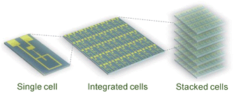 | ||
| Fig. 1 Schematic illustrations representing application of on-chip fuel cells. The single cell can be used as an on-chip power source, and integrated multiple cells and their stacks are applicable as power sources for general electronic devices. This image of a single cell has a large margin for current collectors,6 thus in actual systems the cells can be integrated in higher density. | ||
As for the design, we proposed an unique air-breathing, membraneless and monolithic design, which is suitable for application as on-chip fuel cells.6,14 As shown in Fig. 2a, this on-chip cell is based on a microchannel replicable to other substrates, e.g., to polymers by hot-embossing. The cell operates on a liquid fuel supplied through the microchannel by capillary force and oxygen in the air without pumps, i.e., the entire cell system can be fabricated on a single chip. This fascinating concept for the development of tiny on-chip fuel cells can be realized by introducing three important characteristics. First, the air-breathing design enables the use of oxygen from the air. Oxidant supply is an important issue for miniature fuel cells due to the large energy-loss caused by the strong capillary force in microchannels, thus an air-breathing design was applied. Second, the membraneless design is beneficial in terms of elimination of a bulky membrane and of the assembly process associated with it. Third, a monolithic design is of great importance as we previously described.
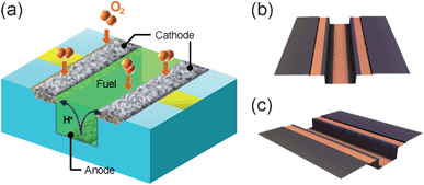 | ||
| Fig. 2 Introduction to our on-chip fuel cell system. (a) A schematic illustration explaining the design. Protons are generated by fuel oxidization on the anode, deposited on the bottom of a microchannel, transferred to the cathode through a fuel solution containing ion conductors, and then reacted with oxygen to become water. (b and c) Color confocal microscope images of an on-chip fuel cell fabricated using Si microfabrication techniques. The orange regions are Au current collectors. | ||
This unique design was realized by (i) the synthesis of a Pd–Co alloy, which was highly active in oxygen reduction reaction and tolerant to methanol,15,16 using electrodeposition,17,18 and (ii) the precise fabrication of microelectrodes with a narrow distance between them using microfabrication techniques. Previously, the cell had been demonstrated to operate on a methanol solution containing sulfuric acid or sodium sulfate as the supporting electrolyte,6 which was necessary for the smooth ion-transfer between the anode and the cathode (Fig. 2a). The performance was relatively high (ca. 1.4 µW) among on-chip fuel cells.6 However, a concern remains about the risk of using methanol solution containing sulfuric acid, because the cell is of open-air design.
In view of this, this work focuses on the fuel and investigates two alternatives to methanol. We chose ethanol and 2-propanol as a fuel alternative to methanol, and also investigated the use of phosphate buffer to realize safe operation of the cell. Ethanol was chosen as a less toxic fuel and moreover as a renewable energy source, which attracts increasing attention. 2-Propanol was chosen as a fuel for high power operation, because this fuel is known not to produce carbon monoxide as an intermediate, and thus the catalyst poisoning issue for platinum catalyst can be avoided.19–21 As for the supporting electrolyte, sodium sulfate had been used as a neutral salt in our previous work, but the cell performance was drastically decreased in the initial several minutes.6 Since the voltage decrease was considered to be caused by local pH change around the electrodes, a phosphate buffer solution was used in this work to realize safe operation of the cell. This work is considered to demonstrate the feasibility of this cell design for applications in a variety of fields.
The cell was fabricated on a Si substrate through a series of microfabrication procedures, following our previously published report.6 In brief, a shallow trapezoidal channel (5 µm deep, 400 µm wide, and 6 mm long) was etched with a KOH solution after photolithography. The channel was further etched by deep-reactive ion etching to obtain a deeper rectangular channel (100 µm deep and 200 µm wide) in the central portion of the shallow channel after photolithography. On the channel, Au current collectors were deposited as shown in the color confocal microscope images of Fig. 2b and c (3CCD Real Color Confocal Microscope, H300, Lasertech). Finally, Pd–Co alloy was electrodeposited as the cathode catalyst at −200 mA cm−2 for 60 s in a solution containing an ammonia complex of Pd(II) and a malonic acid complex of Co(II), and Pt–Ru alloy was electrodeposited as the anode catalyst by applying a pulse current, as reported previously.18,22 Details of the electrodeposition processes are described in the ESI†.
The cell performance was evaluated at room temperature using a fuel solution containing 2 M alcohol (methanol, ethanol or 2-propanol) and a supporting electrolyte (0.5 M sulfuric acid or phosphate buffer: 0.25 M Na2HPO4 + 0.25 M KH2PO4, pH 6.9). The solution was dropped on the end of a microchannel to be supplied by capillary force. Current–voltage (I–V) curves were recorded on an electrochemical instrument (HZ-3000, Hokuto Denko). During the I–V measurements, the potentials of each individual electrode were measured using a silver/silver chloride (Ag/AgCl) reference electrode set in the fuel solution at the end of the channel. In addition, the fuel oxidation characteristics on a Pt–Ru electrode prepared by electrodeposition (same as the anode of the cell, 3 mmϕ) were evaluated by cyclic voltammetry in a conventional three-electrode cell containing an air-saturated fuel solution.
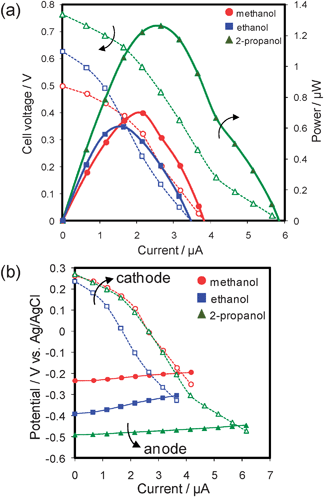
The performance of the cell operating on an acidic fuel solution is shown in Fig. 3. The I–V curves (Fig. 3a) show that the cell operating on ethanol and 2-propanol can generate voltages comparable with that of methanol, indicating that this cell system can be used not only for methanol, but also for ethanol and 2-propanol. Moreover, the Pd–Co catalyst was found to be active selectively in oxygen reduction reaction even in ethanol and 2-propanol solutions as shown in the current–potential (I–E) curves (Fig. 3b). The cathode potentials were largely unaffected by the use of 2-propanol, as well as methanol, and only slightly by the use of ethanol. The potential decrease in the case of ethanol may be attributed to adsorption of ethanol on the surface of the Pd–Co catalyst, from the fact that no obvious oxidation current was observed during oxygen reduction measurements on Pd–Co in the presence of ethanol (see Fig. S1, ESI†).
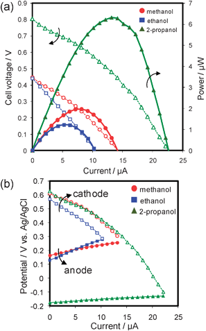 | ||
| Fig. 3 Performance of an on-chip fuel cell operating on an acidic solution containing 2 M alcohol as fuel (circles: methanol; squares: ethanol; triangles: 2-propanol) at room temperature. 30 s point−1. (a) Current–voltage curves (open symbols) and current–power curves (filled symbols). (b) Current–potential curves for each individual electrode (cathode: open symbols; anode: filled symbols). | ||
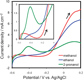
The maximum power (Pmax) of the cell operating on 2-propanol was ca. 6.3 µW, i.e., three times as high as that of methanol (ca. 2.0 µW) and five times as high as that of ethanol (ca. 1.2 µW). These results are attributable to the superior anode performance of the cell on 2-propanol by ∼350 mV to that of the cells on methanol and ethanol (Fig. 3b). This improvement in anode performance was also obtained by the anodic scans of cyclic voltammograms (Fig. 4). The onset potential for 2-propanol oxidation was around −0.2 V vs.Ag/AgCl, i.e., close to the onset potential for hydrogen oxidation. This favorable oxidation characteristic was reported to originate from the fact that the products of 2-propanol oxidation are only acetone and CO2, with a less poisoning effect on the anode.20,23,24 The onset potential of 2-propanol oxidation was quite negative compared with the values reported in the literature to the best of our knowledge.19,21,23,24 This is attributed to the activity of our electrodeposited Pt–Ru catalyst and to the experimental condition using air-saturated solutions, but further investigations are needed and are continuing.
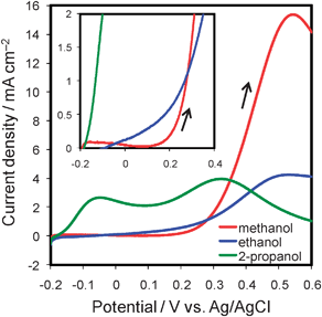 | ||
| Fig. 4 Anodic scans of cyclic voltammograms for fuel oxidation in a conventional three-electrode cell containing a 2 M fuel solution (red: methanol; blue: ethanol; green: 2-propanol) with 0.5 M H2SO4 at room temperature. Scan rate was 5 mV s−1. The inset shows magnified voltammograms of low current region. | ||
As for the energy density of the fuels, although the theoretical values of 2-propanol (8.99 Wh g−1) and ethanol (8.03 Wh g−1) are higher than that of methanol (6.07 Wh g−1),25 incomplete oxidation of 2-propanol and ethanol due to the difficult cleavage of C–C bonds was considered to decrease their practical energy densities.23,24 The voltammograms (Fig. 4) show that the peak current density for the methanol oxidation reaction was about five times as large as that for ethanol and 2-propanol, this may suggest that 2-propanol and ethanol were not completely oxidized to CO2 on the electrodeposited Pt–Ru catalyst. Indeed, 2-propanol was reported to be oxidized mainly to acetone in the presence of plenty of 2-propanol, while it can be oxidized mainly to CO2 in a dilute solution using a porous Pt–Ru electrode.19,20 Thus, the relatively high concentration of 2-propanol used in this work might reduce the degree of its complete oxidation to CO2. Likewise, ethanol was reported to be oxidized partially to acetaldehyde and acetic acid as intermediates, and a little to CO2 at room temperature.26 Although detailed investigations are required to conclude their energy density, 2-propanol is regarded as a possible fuel for devices prioritizing high power. Moreover, we expect that further developments in anode catalyst layers will show 2-propanol as a promising candidate for liquid fuel in on-chip fuel cells.
The performance of the cell operating on a neutral fuel solution is shown in Fig. 5. The I–V curves (Fig. 5a) proved the feasibility of the operation of the on-chip cells using neutral pH solutions. The I–E curves (Fig. 5b) confirm that the cathode catalyst, i.e., Pd–Co, was still selective for oxygen reduction reaction even in neutral solutions. This was also confirmed based on the voltammetry results of the catalyst using a conventional three-electrode cell (see Fig. S2, ESI†). Moreover, the voltages were successfully stabilized by the use of phosphate buffer solution at least for 2 h around 0.35 V at 1.1 µA (Fig. S3, ESI†). The Pmax for ethanol (i.e., 0.6 µW) was as high as that for methanol (i.e., 0.7 µW), and that for 2-propanol was still higher (i.e., 1.3 µW) among these fuels.
 | ||
| Fig. 5 Performance of our on-chip fuel cell operating on a neutral solution containing 2 M alcohol as fuel (circles: methanol; squares: ethanol; triangles: 2-propanol) at room temperature. 30 s point−1. (a) Current–voltage curves (open symbols) and current–power curves (filled symbols). (b) Current–potential curves for each individual electrode (cathode: open symbols; anode: filled symbols). | ||
Comparing the performance of the neutral solutions (pH 6.9) with that of the acidic solutions (pH 0.7), as for cathode potentials, open-circuit potentials were decreased by ca. 0.35 V, corresponding to the difference in Nernst potential of 0.37 V at the pH difference of 6.2. Likewise, anode potentials of methanol and 2-propanol were decreased by almost the same potential (i.e., ca. 0.35 V). Thus, the open-circuit voltages were confirmed to be almost the same between acidic and neutral solutions, except for ethanol. The voltage for a neutral ethanol solution was >100 mV higher than that for an acidic ethanol solution around the open-circuit voltages, this suggests faster oxidation of ethanol in neutral solution. This consideration is supported by the voltammograms (Fig. 4 and 6). Thus, the neutral ethanol solution can be regarded as a promising candidate fuel for applications prioritizing low toxicity.
 | ||
| Fig. 6 Anodic scans of cyclic voltammograms for fuel oxidation in a conventional three-electrode cell containing a 2 M fuel solution (red: methanol; blue: ethanol; green: 2-propanol) with phosphate buffer (pH 6.9) at room temperature. Scan rate was 5 mV s−1. The inset shows magnified voltammograms of low current region. | ||
The Pmax values (Fig. 5a) of the cells on neutral solutions were lower than those on acidic solutions, though the voltages near open-circuit potential were almost the same, except for those of ethanol. The difference in power is attributable to the drastic decrease in cathode potential above ∼2 µA in the case of neutral solutions. The potential decrease might be caused by (i) higher ionic resistance in the porous Pd–Co cathode layer due to low ionic mobility of phosphate buffer compared with the protons of acidic solutions and/or (ii) lower oxygen diffusivity in the cathode layer which may be due to differences in wettability, but detailed investigations are needed for further discussion.
In summary, the on-chip fuel cell was found to operate not only on methanol, but also on ethanol and on 2-propanol. Moreover, cell operation using ethanol and 2-propanol under neutral pH conditions was confirmed using phosphate buffer solutions. These results indicate that the on-chip fuel cell is flexible to fuel solution, thus the solution can be chosen to suit the application of the cell. For example, methanol is suitable for applications requiring long life because of its characteristic propensity to be oxidized to CO2. A neutral ethanol solution is suitable for applications requiring safety, and 2-propanol is suitable for applications prioritizing power. We will optimize the system by choosing the catalyst most suitable for oxidizing each fuel, e.g., Pt–Sn for ethanol.26,27
Acknowledgements
This work was partly supported by the Grant-in-Aid for Specially Promoted Research “Establishment of Electrochemical Device Engineering” and by the Global COE program “Center for Practical Chemical Wisdom” from MEXT, Japan.Notes and references
- D. Niwa, K. Omichi, N. Motohashi, T. Homma and T. Osaka, Sens. Actuators, B, 2005, 108, 721–726 CrossRef.
- R. Popovtzer, T. Neufeld, N. Biran, E. Z. Ron, J. Rishpon and Y. Shacham-Diamand, Nano Lett., 2005, 5, 1023–1027 CrossRef CAS.
- H. Nakano, K. Dokko, J. I. Sugaya, T. Yasukawa, T. Matsue and K. Kanamura, Electrochem. Commun., 2007, 9, 2013–2017 CrossRef CAS.
- D. Golodnitsky, V. Yufit, M. Nathan, I. Shechtman, T. Ripenbein, E. Strauss, S. Menkin and E. Peled, J. Power Sources, 2006, 153, 281–287 CrossRef CAS.
- J. B. Lee, Z. Z. Chen, M. G. Allen, A. Rohatgi and R. Arya, J. Microelectromech. Syst., 1995, 4, 102–108 CrossRef CAS.
- S. Tominaka, S. Ohta, H. Obata, T. Momma and T. Osaka, J. Am. Chem. Soc., 2008, 130, 10456–10457 CrossRef CAS.
- S. Motokawa, M. Mohamedi, T. Momma, S. Shoji and T. Osaka, Electrochem. Commun., 2004, 6, 562–565 CrossRef CAS.
- S. C. Kelley, G. A. Deluga and W. H. Smyrl, Electrochem. Solid-State Lett., 2000, 3, 407–409 CAS.
- M. Hayase, T. Kawase and T. Hatsuzawa, Electrochem. Solid-State Lett., 2004, 7, A231–A234 CrossRef CAS.
- S. J. Lee, A. Chang-Chien, S. W. Cha, R. O'Hayre, Y. I. Park, Y. Saito and F. B. Prinz, J. Power Sources, 2002, 112, 410–418 CrossRef CAS.
- N. T. Nguyen and S. H. Chan, J. Micromech. Microeng., 2006, 16, R1–R12 CrossRef CAS.
- Y. Yamazaki, Electrochim. Acta, 2004, 50, 663–666 CrossRef CAS.
- H. L. Maynard and J. P. Meyers, J. Vac. Sci. Technol., B, 2002, 20, 1287–1297 CrossRef CAS.
- “Fuel cells: Breath of fresh air”, in Asia Materials, Nature Publishing Group, 28th October 2008 (http://www.natureasia.com/asia-materials/highlight.php%3Fid%20%3D%20287) Search PubMed.
- J. L. Fernandez, V. Raghuveer, A. Manthiram and A. J. Bard, J. Am. Chem. Soc., 2005, 127, 13100–13101 CrossRef CAS.
- O. Savadogo, K. Lee, K. Oishi, S. Mitsushima, N. Kamiya and K. I. Ota, Electrochem. Commun., 2004, 6, 105–109 CrossRef CAS.
- S. Tominaka, S. Ohta, T. Momma and T. Osaka, ECS Trans., 2007, 11, 1369–1377 Search PubMed.
- S. Tominaka, T. Momma and T. Osaka, Electrochim. Acta, 2008, 53, 4679–4686 CrossRef CAS.
- E. Pastor, S. Gonzalez and A. J. Arvia, J. Electroanal. Chem., 1995, 395, 233–242 CrossRef CAS.
- S. G. Sun and Y. Lin, Electrochim. Acta, 1996, 41, 693–700 CrossRef CAS.
- S. Sen Gupta and J. Datta, J. Chem. Sci., 2005, 117, 337–344 CrossRef CAS.
- T. Osaka, H. Iida, S. Tominaka and T. Hachisu, Isr. J. Chem., 2008, 48, 333–347 CrossRef.
- C. G. Lee, M. Umeda and I. Uchida, J. Power Sources, 2006, 160, 78–89 CrossRef CAS.
- I. D. Rodrigues, J. P. I. DeSouza, E. Pastor and F. C. Nart, Langmuir, 1997, 13, 6829–6835 CrossRef CAS.
- U. B. Demirci, J. Power Sources, 2007, 169, 239–246 CrossRef CAS.
- C. Lamy and E. M. Belgsir, in Handbook of Fuel Cells, ed. W. Vielstich, A. Lamm and H. A. Gasteiger, John Wiley & Sons, 2004, pp. 323–334 Search PubMed.
- C. Lamy, S. Rousseau, E. M. Belgsir, C. Coutanceau and J. M. Leger, Electrochim. Acta, 2004, 49, 3901–3908 CrossRef CAS.
Footnote |
| † Electronic supplementary information (ESI) available: Experimental procedures and voltammograms for the oxygen reduction reaction in the presence of fuels both in acidic and neutral media. See DOI: 10.1039/b906216e |
| This journal is © The Royal Society of Chemistry 2009 |