Additional layer of the multi-walled carbon-nanotubes increases the photo-current of a poly(3-hexylthiophene)-sensitised solar cell
Atsushi
Furuta
,
Tatsunori
Kuramoto
and
Toru
Arai
*
Department of Applied Chemistry, Faculty of Engineering, Kyushu Institute of Technology, Tobata, Kitakyushu 804-8550, Japan. E-mail: arai@che.kyutech.ac.jp; Fax: +81 93-884-3300; Tel: +81 93-884-3303
First published on 4th June 2009
Abstract
When a layer of multi-walled carbon nanotubes was deposited on the surface of a poly(3-hexylthiophene) layer on a SnO2-modified glass electrode, the maximum power output of a dye-sensitised photovoltaic solar cell increased by a factor of 1.35.
Broader contextPoly(3-hexylthiophene) (p3HT) is often used as the light-absorber for the solar photovoltaic devices, because its thin film is easily fabricated. Various efforts have been devoted to increase the energy-conversion efficiency of the p3HT-based photovoltaic devices. Here, we demonstrate that the addition of a multi-walled carbon nanotubes (MWCNTs) layer on the p3HT-based electrode improved the photo-current and the power output of the solar-cell. The dye-sensitised solar cell was made using an F-doped SnO2 glass (FTO)/nano-structured SnO2/p3HT/MWCNTs electrode as the working electrode. Under illumination with the visible light, the photo-current and the maximum power output was improved compared with the cell without the MWCNTs layer. MWCNTs layer possibly extract the hole from the excited-state p3HT, thus effectively generating the charge-separation state. |
Poly(3-alkylthiophene)s are preferable as the light-harvesting materials for the dye-sensitised solar cell because of their facile fabrication of thin films, the expectation for use in flexible devices and the availability of a variety of chemical structures.1,2 The energy-conversion efficiency of the poly(3-alkylthiophene)s-based solar cells have been improved, for instance, by co-polymerisation with another monomer.3,4Carbon nanotubes (CNTs) are currently attracting attention in electrochemistry, because of their easy transport of the electron and hole.5–8 Here, the poly(3-hexylthiophene) (p3HT) film is modified by coating with the CNTs, expecting an improved photo-voltaic performance as a solar cell. Fig. 1a depicts the modified electrode consisting of a glass electrode coated with the F-doped SnO2 (FTO), the nano-structured SnO2 made from its colloidal solution, p3HT and CNTs (see below for details).
 | ||
| Fig. 1 (a) The modified electrode of FTO/SnO2/p3HT/CNTs. (b) Mechanism for the solar cell with FTO/SnO2/p3HT/CNTs electrode, Pt counter electrode and I−/I3− electrolyte. The role of CNTs is omitted for clarity. | ||
The colloidal SnO2 solution was placed on a conducting glass electrode, FTO glass, according to Kamat et al.9,10 The nano-structured SnO2 layer was formed (FTO/SnO2) to increase the electrode surface area for collecting the photo-generated charges. The electrochemical polymerisation of 3-hexylthiophene yielded the conjugated polymer, p3HT, with the absorption maximum λmax at 430 nm in CHCl3 and 447 nm (with a shoulder at 601 nm, see below) in the film.11 The FTO/SnO2electrode (5.0 mm × 5.0 mm) was coated by the p3HT solution in THF (1.0 g L−1, typically 25 µL) and then dried at room temperature to produce the dye-modified working electrode (FTO/SnO2/p3HT). This dye-modified electrode (FTO/SnO2/p3HT) and the counter electrode (Pt-coated ITO glass) were separated by a polymer-film spacer (50 µm) and the electrolyte solution (CH3CN containing 50 mM I2/0.50 M NaI) was added.12 Under Xe light illumination (>390 nm, using a glass cut-off filter, 100 mW cm−2) of this solar cell, the moderate photo-current (Jsc = −0.80 mA cm−2, normalized for the working electrode area) and photo-voltage (Voc = 0.39 V) were observed (Table 1, entry 2; see Ref. 1 for the current–voltage parameters). The repeated experiments on the photovoltaic cells confirmed the reproducibility of the data. The amount of p3HT loaded on the FTO/SnO2electrode had some influence on the current–voltage properties (entries 1–3), which was optimised to be 25 µg. The photo-excited p3HT releases electrons from its excited state to the FTO/SnO2 anode. Along with the electron transfer, the hole travels from the formed p3HT˙+ to the I−/I3−redox pair and then to the Pt cathode (Fig. 1b).
| Entry | First layer | Load/µg | Second layer | Load/µg | J sc/mA cm−2 | V oc/V | P max/mW cm−2 | Fill factor (%) |
|---|---|---|---|---|---|---|---|---|
| a Counter electrode, Pt-coated ITO; electrolyte, 50 mM I2 and 0.50 M NaI in CH3CN; the area of the modified working electrode, 0.25 cm2; Xe-light (>390 nm) illumination. b CNTs and p3HT were admixed and then loaded. | ||||||||
| 1 | p3HT | 10 | None | — | −0.60 | 0.40 | −0.16 | 65 |
| 2 | p3HT | 25 | None | — | −0.80 | 0.39 | −0.19 | 60 |
| 3 | p3HT | 40 | None | — | −0.72 | 0.39 | −0.18 | 62 |
| 4 | p3HT | 25 | MWCNTs | 1.0 | −0.92 | 0.40 | −0.23 | 62 |
| 5 | p3HT | 25 | MWCNTs | 2.0 | −0.97 | 0.41 | −0.25 | 63 |
| 6 | MWCNTs | 1.0 | p3HT | 25 | −0.56 | 0.38 | −0.12 | 55 |
| 7 | (MWCNTs 2.0 µg + p3HT 25 µg)b | −0.33 | 0.39 | −0.08 | 62 | |||
| 8 | p3HT | 25 | SWCNTs | 1.0 | −0.83 | 0.39 | −0.18 | 57 |
| 9 | p3HT | 25 | SWCNTs | 2.0 | −0.52 | 0.35 | −0.10 | 54 |
| 10 | SWCNTs | 1.0 | p3HT | 25 | −0.61 | 0.36 | −0.13 | 58 |
| 11 | (SWCNTs 1.0 µg + p3HT 25 µg)b | −0.40 | 0.39 | −0.10 | 63 | |||
The FTO/SnO2/p3HT electrode was further coated with the multi-walled carbon nanotubes (MWCNTs, Aldrich) by depositing the suspension of MWCNTs in THF (0.10 g L−1, prepared by 30 min sonication, typically 20 µL) on the FTO/SnO2/p3HT electrode and drying at room temperature. The FE-SEM image of an FTO/SnO2/p3HT/MWCNTs electrode (Fig. 2) shows the almost flat surface of FTO/SnO2/p3HT with some crystalline structure. The well-dispersed MWCNTs of ca. 200 nm diameter and 2.5 µm length are on the FTO/SnO2/p3HT layer. The solar cell consisting of this FTO/SnO2/p3HT/MWCNTs electrode (MWCNTs 2.0 µg, Table 1, entry 5) showed an increased photo-current (Jsc = −0.97 mA cm−2) compared to that without the MWCNTs (Jsc = −0.80 mA cm−2, entry 2) upon Xe-light illumination. The photo-voltage of this solar-cell (Voc = 0.41 V) was essentially the same as that without the MWCNTs (0.39 V). The photo-current represents the light-harvesting efficiency or the charge-injection from the excited dye to the electrode.12 The photo-voltage depends on the energy-gap between the quasi-Fermi level of electrons in the SnO2electrode and the potential of the I−/I3−redox pair in the electrolyte. The coating of the MWCNTs on the FTO/SnO2/p3HT electrode improved the photo-current by a factor of 1.21 and only slightly altered the photo-voltage, suggesting that the MWCNTs improved the charge-injection.
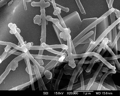 | ||
| Fig. 2 FE-SEM image of the surface of FTO/SnO2/p3HT/MWCNTs (2.0 µg) electrode. | ||
The wavelength dependence of the incident photon-to-photocurrent efficiency (IPCE)1 was measured for the solar cell consisting of the FTO/SnO2/p3HT/MWCNTs (2.0 µg) electrode (Fig. 3, curve A). The IPCE spectrum shows a peak at 430 nm (14.0% efficiency), which is slightly blue-shifted from the λmax of p3HT film (447 nm, curve B). The peak derived from the MWCNTs is not observed in Fig. 3A. This IPCE spectrum clearly indicated that the light-absorption by the p3HT is responsible for the photo-current and the photo-voltage.
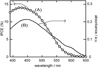 | ||
| Fig. 3 (A) The IPCE spectrum of the solar cell consisting of FTO/SnO2/p3HT/MWCNTs (2.0 µg) electrode and (B) the absorption spectrum of the p3HT film. | ||
Fig. 4 shows the J–V profiles of the solar cells consisting of the FTO/SnO2/p3HT electrode (curve A; Table 1, entry 2) and FTO/SnO2/p3HT/MWCNTs (2.0 µg) electrode (curve B; entry 5). For the MWCNTs-coated electrode (curve B), Jsc was −0.97 mA cm−2 at the zero external potential (V = 0 V). The photo-current gradually decreased with the increasing external potential, then sharply and finally crossed the abscissa (J = 0 mA cm−2) with the Voc of 0.40 V. The maximum power output, Pmax, is −0.25 mW cm−2 at Jmpp = −0.84 mA cm−2 and Vmpp = 0.30 V. The Pmax value of the FTO/SnO2/p3HT electrode (curve A) is −0.19 mW cm−2 (Jmpp = −0.68 mA cm−2, Vmpp = 0.27 V). The coating by the MWCNTs increased the maximum power output by a factor of 1.35. The fill factor, defined as Pmax/(JscVoc), for entry 5 is 63%, which is moderately high. The transport (and the recombination) of the charge carrier in the semi-conductive SnO2 layer determines the fill factor, therefore, the lifetime and the mobility of the charge carrier are important.1 Also, the series resistance of the cell influences the fill factor. The moderately high fill factors of the solar cells in this study (Table 1) demonstrate the fineness of the nano-structured SnO2-modified electrodes developed by Kamat et al.9 Also, these acceptable fill factors indicate the lack of any short-circuit in the solar cells, suggesting a sufficient coverage by the dye-layer(s).
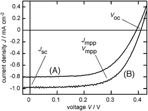 | ||
| Fig. 4 Photo-voltaic properties of the solar cells with the working electrode of (A) FTO/SnO2/p3HT and (B) FTO/SnO2/p3HT/MWCNTs (2.0 µg). Pt counter electrode, I−/I3− electrolyte, and Xe-light (>390 nm) illumination. | ||
Fig. 5 (line A) shows the photo-current Jsc of the solar cell consisting of the FTO/SnO2/p3HT/MWCNTs working electrode (25 µg p3HT layer) as a function of the loaded MWCNTs. The photo-current Jsc without MWCNTs, with 0.5 µg, 1.0 µg and 2.0 µg MWCNTs were −0.80, −0.84, −0.92 and −0.97 mA cm−2, respectively. The photo-current Jsc almost linearly increased with the increasing coverage by the second layer of MWCNTs. Again, the photo-voltage Voc and the fill factor only slightly changed with the varying amount of the coated MWCNTs, suggesting that the MWCNTs improved the charge-injection step. Some of the photovoltaic parameters are listed in Table 1 (entries 4 and 5). The coating with 4.0 µg MWCNTs substantially decreased the photo-current. The hole transport from the p3HT layer to the electrolyte is probably hindered by too thick (4.0 µg) a coating by the MWCNTs.
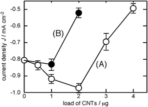 | ||
| Fig. 5 Current density of the solar cell with working electrode of FTO/SnO2/p3HT covered by (A) MWCNTs and (B) SWCNTs. p3HT 25 µg, Pt counter electrode, I−/I3− electrolyte, and Xe-light (>390 nm) illumination. | ||
We now wish to consider why 2.0 µg of the MWCNTs layer increased the photo-current of the solar cell consisting of FTO/SnO2/p3HT/MWCNTs. (1) As Miller et al. reported,13 the MWCNTs may be capable of extracting a hole. If the MWCNTs in the FTO/SnO2/p3HT/MWCNTs electrode tend to extract a hole from the excited p3HT* or the intermediate cation radical, p3HT˙+, the charge separation on the electrode would take place as illustrated in Fig. 6. The electron transfers from the p3HT layer to SnO2 and then to FTO, and in turn, the hole transfers from the p3HT layer to the MWCNTs, I−/I3−redox pair and to the Pt cathode (Fig. 6).15,16 In this context, McGehee et al. deeply examined the electron transfer from the excited state p3HT to the inorganic anodic materials.14 (2) The hole transfer from the p3HT to the MWCNTs is thermodynamically possible. The hole extraction by the MWCNTs will avoid any undesired charge recombination in the electrode, thus increasing the photo-current of the solar cell. (3) The hole collection of the MWCNTs from the photo-excited poly(p-phenylenevinylene) has also been reported, supporting the above explanation.17 (4) Actually, when the FTO/SnO2electrode was first coated with the MWCNTs and then with p3HT as the second layer (Table 1, entry 6), the photo-current decreased to −0.56 mA cm−2. The photo-current is decreased for the FTO/SnO2/MWCNTs/p3HT arrangement, because (1) both the electron transfer from p3HT* to SnO2 and the hole transport from p3HT* to MWCNTs may take place or (2) MWCNTs may function as the recombination centres.
 | ||
| Fig. 6 Schematic diagrams of the conduction band of SnO2, HOMO and LUMO of p3HT and the work function of MWCNTs, showing the electron transfer from the photo-excited p3HT to SnO2 and the role transfer to MNCNTs. | ||
Interestingly, the use of single-walled carbon nanotubes (SWCNTs, Fig. 5, line B) instead of MWCNTs only resulted in a slight increase in the photo-current. The photo-current Jsc with coating by 1.0 µg of the SWCNTs was −0.83 mA cm−2, which was merely a slight improvement compared to that without the CNTs (−0.80 mA cm−2). The photo-current significantly dropped with 2.0 µg of the SWCNTs (−0.52 mA cm−2). The SWCNTs have been utilized as electron acceptors in the photo-induced electron transfer system, such as the Ru complex/TiO2/SWCNTs systems.18 It may be postulated that the SWCNTs tend to extract an electron from the photo-excited state of p3HT (p3HT*), but not extracting a hole like the MWCNTs. If the SWCNTs extract an electron from p3HT*, the reverse electron flow takes place, therefore, the net photo-current of the solar cell will decrease. The energy transfer from the excited-state p3HT (p3HT*) to the SWCNTs as in the case of SWCNTs/poly(p-phenylenevinylene) system10 may rationalize the inefficiency of the SWCNTs layer. The energy transfer means the quenching of the excited-state p3HT*, which will result in the decreased photo-current. Supporting the above discussion, recent DFT calculations indicated the ground-state charge-transfer from the p3HT to the metallic carbon nanotubes, in which the exciton dissociation step could be unfavorable.19 It should be considered also that SWCNTs contain not only metallic but semiconducting CNTs, which do not facilitate the hole extraction. The difference in the size of MWCNTs and SWCNTs might have an effect.
The interactions between p3HT and CNTs (MWCNTs and SWCNTs) in THF solution were examined spectroscopically. The absorption spectrum of p3HT in THF (37 mg L−1, λmax 430 nm) did not change upon the titration with the THF solution of CNTs (MWCNTs or SWCNTs, 50 mg L−1, prepared by 30 min sonication) even with the addition of the 40 µg of CNTs. There may be little ground-state interaction between p3HT and CNTs. In contrast, the fluorescence emission spectrum of p3HT in THF drastically decreased by the addition of the suspension of MWCNTs in THF (Fig. 7a). The addition of 40 µg of MWCNTs decreased the emission intensity of p3HT to 48%, without changing the emission λmax (568 nm with the shoulder peak at ∼620 nm). Interestingly. the addition of the same amount of 40 µg SWCNT decreased the emission intensity of p3HT only to 85% (Fig. 7b). In fact, the Stern–Volmer plot (Fig. 8) indicated that the quenching efficiency of MWCNTs was much larger than that of SWCNTs, that is, the Stern–Volmer parameter KSV was 98 L mg−1 for MWCNTs and 17 L mg−1 for SWCNTs. These spectroscopic studies indicated that MWCNTs and SWCNTs both quenched the excited-state of p3HT in the THF solution and MWCNTs quenched more efficiently than SWCNTs. There may be various possible quenching mechanisms and further study is necessary to clarify.20 Though, the efficient quenching of the excited p3HT by MWCNTs in THF solution may be concerned with the increased photo-current of the p3HT photovoltaic cell upon the addition of the MWCNTs layer.
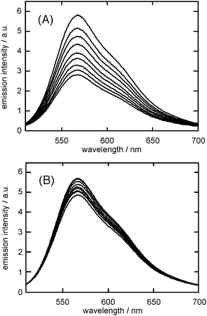 | ||
| Fig. 7 Fluorescence spectra (λex = 430 nm) of p3HT in THF (37 mg L−1) containing 0, 5, 10, 15, 20, 25, 30, 35 and 40 µg of (A) MWCNTs and (B) SWCNTs. | ||
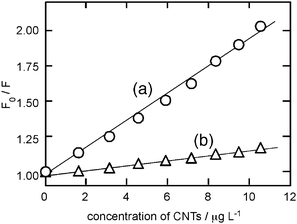 | ||
| Fig. 8 Stern–Volmer plots for the fluorescence quenching of p3HT in THF (37 mg L−1, λem = 568 nm) by (a) MWCNTs and (b) SWCNTs. | ||
In conclusion, the addition of the MWCNTs layer on the FTO/SnO2/p3HT electrode enhanced the photo-current and the maximum power output by factors of 1.21 and 1.35, respectively, of a dye-sensitised solar cell. By coating the FTO/SnO2/p3HT electrode with a 2.0 µg of the MWCNTs, Jsc of −0.97 mA cm−2, Voc of 0.40 V, Pmax of −0.25 mW cm−2, the fill factor of 63% and the IPCE of 14.0% at 430 nm were noted. The MWCNTs layer significantly increased the Jsc, but only slightly for Voc and the fill factor, suggesting that the MWCNTs improved the charge-injection step. MWCNTs may extract a hole from the excited p3HT* or the cation radical, p3HT˙+, to effectively generate the charge separation state. The addition of the SWCNTs layer was ineffective, probably because the SWCNTs may tend to extract an electron from the p3HT layer.
The authors thank Professor S. Hayase, Professor R. Shiratsuchi and Mr. S. Kondo of Kyushu Institute of Technology for the electrochemical measurements.
References
- S. Günes, H. Neugebauer and N. S. Sariciftci, Chem. Rev., 2007, 107, 1324–1338 CrossRef.
- E. Bundgaard and F. C. Krebs, Sol. Energy Mater. Sol. Cells, 2007, 91, 954–985 CrossRef CAS.
- C.-P. Chen, S.-H. Chan, T.-C. Chao, C. Ting and B.-T. Ko, J. Am. Chem. Soc., 2008, 130, 12828–12833 CrossRef CAS.
- E. L. Ratcliff, J. L. Jenkins, K. Nebesny and N. R. Armstrong, Chem. Mater., 2008, 20, 5796–5806 CrossRef CAS.
- B. J. Landi, R. P. Raffaelle, S. L. Castro and S. G. Bailey, Prog. Photovolt: Res. Appl., 2005, 13, 165–172 CrossRef CAS.
- E. Kymakis, E. Koudoumas, I. Franghiadakis and G. A. J. Amaratunga, J. Phys. D: Appl. Phys., 2006, 39, 1058–1062 CrossRef CAS.
- T. Umeyama, N. Kadota, N. Tezuka, Y. Matano and H. Imahori, Chem. Phys. Lett., 2007, 444, 263–267 CrossRef CAS.
- L. Agüi, P. Yanez-Sedeno and J. M. Pingarron, Anal. Chim. Acta, 2008, 622, 11–47 CrossRef.
- I. Bedja, S. Hotchandani and P. V. Kamat, J. Phys. Chem., 1994, 98, 4133–4140 CrossRef CAS.
- T. Umeyama, N. Tezuka, M. Fujita, S. Hayashi, N. Kadota, Y. Matano and H. Imahori, Chem.–Eur. J., 2008, 14, 4875–4885 CrossRef.
- S. Hotta, S. D. D. V. Rughooputh, A. J. Heeger and F. Wudl, Macromolecules, 1987, 20, 212–215 CrossRef CAS.
- N. R. Neale, N. Kopidakis, J. von de Lagemaat, M. Grätzel and A. J. Frank, J. Phys. Chem. B, 2005, 109, 23183–23189 CrossRef CAS.
- A. J. Miller, R. A. Hatton and S. R. P. Silva, Appl. Phys. Lett., 2006, 89, 133117(1)–133117(3).
- V. Gowrishankar, S. R. Scully, A. T. Chan, M. D. McGehee, Q. Wang and H. M. Branz, J. Appl Phys., 2008, 103, 046511(1)–046511(8).
- M. Onoda, K. Tada, A. A. Zakhidov and K. Yoshino, Thin Solid Films, 1998, 331, 76–81 CrossRef CAS.
- R. A. Hatton, A. J. Miller and S. R. P. Silva, J. Mater. Chem., 2008, 18, 1183–1192 RSC.
- H. Ago, K. Petritsch, M. S. P. Shaffer, A. H. Windle and R. H. Friend, Adv. Mater., 1999, 11, 1281–1285 CrossRef CAS.
- P. Brown, K. Takechi and P. V. Kamat, J. Phys. Chem. C, 2008, 112, 4776–4782 CrossRef CAS Refs cited therein.
- Y. Kanai and J. C. Grosman, Nano Lett., 2008, 8, 908–912 CrossRef CAS.
- K. Suzuki, M. Yamaguchi, M. Kumagai and S. Yanagida, Chem. Lett., 2003, 32, 28–29 CrossRef CAS.
| This journal is © The Royal Society of Chemistry 2009 |
