Carbon nanotube network modified carbon fibre paper for Li-ion batteries
Jun
Chen
*a,
Jiao Zhao
Wang
b,
Andrew I.
Minett
a,
Yong
Liu
a,
Carol
Lynam
a,
Huakun
Liu
b and
Gordon G.
Wallace
*a
aARC Centre of Excellence for Electromaterials Science, Intelligent Polymer Research Institute, University of Wollongong, NSW 2522, Australia. E-mail: junc@uow.edu.au; Fax: +61-2-42213114; Tel: +61-2-42213781
bARC Centre of Excellence for Electromaterials Science, Institute for Superconducting and Electronic Materials, University of Wollongong, NSW 2522, Australia
First published on 26th January 2009
Abstract
Here we report on the direct deposition of large quantities of highly porous carbon nanotube networks onto a carbon fibre paper support; subsequently utilised as the anode in a Li-ion battery application showing improved long-term performance and chemical stability with a significant fully reversible capacity of 546 mAh g−1.
Broader contextThe use of nanostructured carbon materials as electrodes in energy devices has been an active area of research intensity. Here we report on a versatile method of directly depositing large quantities of carbon nanotube network onto a commercially available carbon fibre paper. The CVD process utilises a novel organic ferric salt (iron(III)–tosylate (Fe(III)pTS)) as the catalyst, demonstrating a simple, scalable and cost effective process for the preparation of novel modified electrodes. These CNT modified electrodes can be directly used in energy devices, such as the anode in a Li-ion battery without further processing. This composite electrode showed a significant fully reversible capacity of 546 mAh g−1 (based on CNTs) after 50 cycles. The resultant CNT/CFP electrodes have created a superior stable electrode material for use in electrochemically driven alternative energy applications such as batteries, supercapacitors or fuel cell devices. The other advantage of this process is that this method can be expanded to other electrode substrates which may have wide ranging applications in many areas of energy and environmental science. |
Introduction
The use of nanostructured carbon materials as electrodes in electrochemical devices has been an active area of research intensity. The physical and chemical properties of nanostructured carbon are considered ideal candidates for producing specific energy densities significantly higher than the theoretical limit of graphite and macroscale carbonaceous materials, which are limited by the thermodynamic equilibrium saturation composition of LiC6.1,2 Various single-wall and multi-wall carbon nanotube electrodes have been constructed with varying results (80–640 mAh g−1).3–5 Structural or chemical modification procedures have also been shown to increase the irreversible specific capacities to values as high as 1229 mAh g−1.3 The need to create novel electrode materials that are flexible and light-weight in design has led to the development of binder free composite electrodes with specific capacities as high as 275 mAh g−1.6In recent work we have described a novel modified chemical vapour deposition (CVD) process for depositing carbon nanotube networks (Nanoweb) on metallic substrates,7 which is in contrast to conventional plasma-enhanced CVD methods which are limited by scalability issues, mechanical connection between the CNTs and the substrates8,9 or poor electrochemical properties.10 The CNT Nanoweb networks contain entangled multi-wall carbon nanotubes and exhibit vastly superior electrochemical properties when compared to vertically aligned MWNT forests or SWNT bucky paper.11,12 This process provides an exciting advance in the preparation of novel CNT modified conductive substrates via direct CVD growth. Here we report on the versatility of the method by directly depositing large quantities of carbon nanotubes onto a commercially available carbon fibre paper (CFP, Ballard Inc.) via a modified CVD process using a novel organic ferric salt (iron(III)–tosylate (Fe(III)pTS)) as the catalyst. Preliminary studies on these CNT network/CFP composite electrodes (CNT/CFP) when utilized as the anode in a Li-ion battery application shows improved long-term performance and chemical stability, whilst maintaining the porosity and flexibility of the initial substrate.
Experimental details
In a typical experiment, a thin film of the catalyst, ferric(III) p-toluenesulfonate (Fe(III)pTS), was coated onto the carbon fiber paper (4 × 5 cm2) (CFP) viadip-coating (immersed in Fe(III)pTS solution for 10 s) and then directly annealed in a conventional oven at 100 °C for 10 min. The annealing in the oven (accelerating the evaporation of solvent) helped form a smooth Fe(III)pTS film without crystallisation visible under an optical microscope.Chemical vapour deposition (CVD) was carried out using a commercially available Thermal CVD System (Atomate, USA) which allowed software control of the gas flow rates, individual furnace temperatures, deposition time and vacuum level. The CVD system was first flushed with argon gas (Ar, 150 ml min−1) for 30 min in order to flush away any oxygen in the reactor (quartz tube, 1.5 m, diameter 50 mm), then the temperature of the furnace was increased under a mixed gas flow of argon (Ar, 150 ml min−1) and hydrogen (H2, 20 ml min−1), until it reached 500 °C. The furnace temperature was then held at 500 °C for 20 min for the reduction of the iron(III) to iron nanoparticles by hydrogen gas. The temperature was then increased again, up to 700 °C, whereupon acetylene (C2H2) was introduced for 30 min, at the gas flow rates of Ar (200 ml min−1), C2H2 (10ml min−1) and H2 (3 ml min−1) for the growth process. After growth, the furnace was turned off and the acetylene and hydrogen gases were also turned off, while the argon gas (200 ml min−1) was continuously flushed through the quartz tube until the temperature was less than 100 °C.
Commercially available CR 2032 type coin cells were assembled in an Ar gas filled glove box (MBraun, Unilab, Germany) by staking a porous polypropylene membrane as the separator between the CNT/CFP electrode and a lithium foil counter electrode. The electrolyte filled in the coin cell was 1.0 M LiPF6 in a mixture of ethylene carbonate (EC)/dimethyl carbonate (DMC) (1 : 1 by volume, provided by MERCK KgaA, Germany). The test cell was galvanostatically charged/discharged at room temperature between 0.01 V and 2.00 V using a commercially available battery testing system (Neware, Electronic Co. China) under different constant charge/discharge current densities (0.05, 0.2, and 0.5mA cm−2) for the time required to reach the potential limit. These discharge current densities were related to the different discharge rates, 1C, 4C, and 10C (respectively).
Results and discussion
The resultant CNT nanoweb growth (Fig. 1) was observed to be significantly different to carbon nanotubes grown using conventional inorganic iron catalysts. Scanning electron microscopy (SEM) (Fig 1(a–c)) revealed the growth of a CNT layer on top of the CFP support. Transmission electron microscopy (TEM) (insert in Fig.1(c)) confirmed that the layer was indeed composed of multi-wall carbon nanotubes, approximately 30 nm in diameter, with a bamboo structure. Fig 1(b) indicates that a dense entanglement of CNTs have entirely covered the individual carbon fibres whilst still maintaining the overall porous microstructure of the carbon fibre paper. This implies that the individual fibre was first covered by a continuous film of catalyst material, which resulted in the subsequent growth of a dense CNT NanoWeb. The images in Fig. 1 highlight the uniformity of the coverage of the CNT network on each individual fibre. This is in contrast to results reported in the literature, where uniformity of coverage has been a problem, including the use of techniques such as the ELD deposition of catalysts followed by HFCVD.13 The SEM image of the root/tip area of the fibre (Fig. 1(c)) gives an indication of the extremely porous nature of the CNT deposited network. This suggests that many of the individual carbon nanotubes on each carbon fibre are highly accessible for electrochemical cycling processes, which significantly increases the available electroactive surface area; a key parameter for electrochemical devices.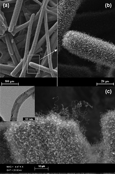 | ||
| Fig. 1 Scanning Electron Micrograph (SEM) images of CNT modified carbon fibre paper shows: (a) and (b) a dense entanglement of carbon nanotube network which entirely covers the individual carbon fibres whilst still retaining the microporous nature of the host carbon fibre paper; (c) high resolution image of the CNT modified carbon fibre and (inset) Transmission Electron Microscope (TEM) image of an individual multi-wall carbon nanotube grown on the CFP. | ||
Fig. 2 shows a Raman spectra obtained. (a) Blank CFP (treated at the same temperature for CNT growth under argon gas) and (b) CNT/CFP electrodes. Whilst both spectra show D-(1329 cm−1), and G-(1591 cm−1) bands common to carbon based materials, there are significant differences in the two spectra in support of the microscopy evidence. (Fig. 1) shows that the structures deposited onto the CFP bare electrode after the growth process are indeed carbon nanotubes. While in Fig. 2(b), we see that the two peaks are well resolved and show prominent peak narrowing, indicating multi-wall nanotube growth in line with spectra commonly reported in the literature.14,15 The full-width-at-half-maximum (FWHM) intensity of the various carbon impurity D-bands is generally much broader than that of the nanotube D-band, which can be used as an indication of the purity level of the sample and may be obtained by simply examining the line-width of the D-band.16 A second indication of the relative graphitization of the deposited material can be expressed as the ratio of ID/IG.14 Consequently, the lower this ratio is, the greater the degree of graphitization of the carbon deposit, suggesting nanotube growth. The ratios of the band intensities shown in Fig. 2 are (a) ID/IG = 1.33 and for the nanotube film (b) ID/IG = 0.77, suggesting a higher degree of graphitization.
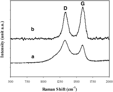 | ||
| Fig. 2 Raman spectra of (a) blank carbon fiber paper (treated at the same temperature for CNT growth under Ar gas) and (b) CNTs modified carbon fiber paper, using 632.8 nm diode laser excitation on 900 lines/mm grating at room temperature. | ||
The tangled CNT/CFP composites are mechanically robust, without any visual signs of degradation during mechanical deformation (90° bending), suggesting that the underlying carbon layer (formed during the CNT growth process7) strongly adheres to the carbon fibre network. After the growth process, the resulting CNT modified CFP can be directly used as an electrode material in assembling electrochemical devices without further treatment. Alternatively, the modified CFP can also be used as a template for further chemical modification.
The electrochemical properties of this CNT/CFP electrode characterised by cyclic voltammetry (CV) (Fig. 3), showed very stable, high electrochemical activity (ip = ∼ 0.4 A g−1) at low scan rates (10 mV s−1) in aqueous solution containing 10 mM K4Fe(CN)6/0.1 M NaNO3, highlighting the extraordinary current carrying capacity of our novel CNT/CFP electrode (Fig. 3(a)). According to the Randles–Sevcik equation, the electroactive area of the CNT network is approximately 143.1 m2 g−1. Recorded as amp g−1 for clarity (based on the mass of the CNTs), the observed ip of the CNT/CFP was over 5× larger than a commercially available multi-wall carbon nanotube mat (NanoLab, USA) (Fig. 3(b)). This suggests that the CNT/CFP electrode has a much higher (over 5×) and more importantly accessible electroactive area compared to the commercial multi-wall CNT paper. This electrolyte accessibility is maintained when the CNT/CFP electrode is assembled into an electrochemical device.
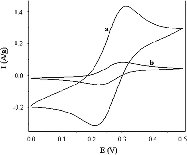 | ||
| Fig. 3 Cyclic voltammograms performed in a conventional three-electrode cell where the working electrode was (a) CNT/CFP (normalised by CNT network including the tangled CNTs and the bottom carbon layer) and (b) commercial MWCNT mat (NanoLab, Boston) in aqueous 10 mM K4Fe(CN)6/0.1 M NaNO3 under identical experimental conditions. The y-axis is displayed as amp g−1 so direct comparison between the two different morphologies can be made. Scan rate: 10 mV s−1. | ||
To further illustrate the electrochemical performance in a device, we have assembled a piece of CNT/CFP electrode into a rechargeable Li-ion coin cell using methods described previously17 in an Ar-filled glove box (MBraun, Unilab, Germany) for battery testing (Neware, Electronic Co. China) using 1.0 M LiPF6 in ethylene carbonate/dimethyl carbonate (50 : 50) (Merck KgaA, Germany) as the electrolyte. The cell was cycled at room temperature between 0.01 V and 2.00 V under different constant charge/discharge current densities (0.05, 0.20, and 0.50 mA cm−2) for the time required to reach the potential limit.
Fig. 4 shows the first to fiftieth charge/discharge curves (under constant current density 0.05 mA cm−2), highlighting the extremely stable electrochemical performance for the modified CNT/CFP electrode. The shape of the curves is similar to those observed previously from carbon nanotube materials, including both SWNT and MWNT.18 The electrochemical stability of these charge-discharge curves indicates a highly reversible insertion/extraction process of Li ions into/from the carbon nanotube structure due to the unique nanostructured, high surface area of the CNT/CFP electrode. Coupled with mechanical and electrochemical robustness and the inherent flexibility of the material,19 these results highlight possible applications in a range of technological areas, not limited to Li-ion batteries.
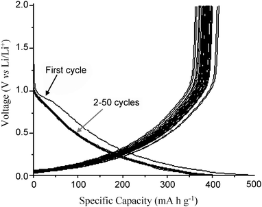 | ||
| Fig. 4 The first to fiftieth charge/discharge profiles of the CNT/CFP electrode as the anode material in a commercial CR2032 coin cell. The current density was 0.05 mA cm−2. | ||
The reversible capacities of the CNTs [normalized against the data of the pure carbon fibre paper obtained in a control experiment (Fig.5(a))] as a function of the cycle number are shown in Fig. 5, demonstrating the viability of the CNT networks as an anode material. The initial capacity of the CNT networks is as high as 643 mAh g−1 under the constant discharge rate of 0.05 mA cm−2. After 50 cycles, the CNT networks still demonstrated a significant, fully reversible capacity of 546 mAh g−1 (Fig.5(b)), which is much higher than the theoretical capacity of graphite (372 mAh g−1) when used as an anode.20 The electrochemical performance of the CNT/CFP electrode displayed an inherent long-term cycling stability, which is in stark contrast to the decrease in discharge capacity normally observed during the cycling of CNT-based electrodes.21 This highly reversible capacity obtained for our CNTs deposited on CFP electrode is possibly attributed to its novel extremely stable and porous 3D-nanostructure. The enhanced performance could be due to the significant specific electroactive area after the CNT network modification. After coin cell electrochemical cycling, it was observed that there was no degradation to the composite electrode and no colour change of the electrolyte over 50 cycles. This observation confirms the electrochemical stability of our 3D network, which is vital in obtaining a high reversible capacity. It is assumed that the super-accessible specific surface area permits large concentrations of Li ion insertion and extraction to occur during cycling. This result is in stark contrast to the values obtained from other CNT-based electrode structures.11,22
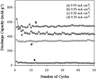 | ||
| Fig. 5 Discharge capacity vs. cycle number for (a) pure CFP electrode without CNTs and CNTs deposited on CFP at different charge/discharge rates (these values are normalized to the native CFP capacity to show the capacity of the CNT themselves); (b) 0.05 mA cm−2, (c) 0.20 mA cm−2, and (d) 0.50 mA cm−2. | ||
Preliminary studies on applying different charge/discharge rates (Fig. 5(c) and 5(d)) were carried out to investigate this new electrode performance under high power density. Whilst the charge/discharge capacity values are lower than those recorded at low current densities, the observed results still show a high reversible capacity of 338 mAh g−1 based on the CNT networks themselves, when increasing the charge/discharge rate up to ten times from 0.05 mA cm−2 to 0.5 mA cm−2. This suggests that this kind of CNT/CFP electrode also has potential in the application of high power battery devices as an anode material.
Conclusions
Here we demonstrate a simple, scalable and cost effective process for the preparation of novel CNT network modified carbon fibre paper electrodesvia a CVD process that can be directly used as the anode material in a Li-ion battery. This composite electrode showed a significant fully reversible capacity of 546 mAh g−1 (based on CNTs) after 50 cycles. The resultant CNT/CFP electrodes have created a superior stable electrode material for use in electrochemically driven alternative energy applications such as batteries, supercapacitors or fuel cell devices.Acknowledgements
We thank the Australian Research Council, ARC Centre of Excellence for Electromaterials Science, and University of Wollongong for continued financial support and Ballard Material Products Inc. for supplying the carbon fiber paper. AIM acknowledges an ARC QEII Research Fellowship.References
- K. Kinoshita, Carbon: electrochemical and physicochemical properties, Wiley, New York, 1988, 293–387 Search PubMed.
- T. Osaka, M. Datta, Energy storage systems for electronics, Gordon, Singapore, 2000, 193–251 Search PubMed.
- J. Y. Eom, H. S. Kwon and O. Zhou, Carbon, 2004, 42, 2589–2596 CrossRef CAS.
- Y. P. Wu, E. Rahm and R. Holze, J. Power Sources, 2003, 114, 228 CrossRef CAS.
- Y. P. Wu, E. Rahm and R. Hilze, Chin. J. Batteries (Dianchi), 2003, 33, 47 Search PubMed.
- J. M. Rosolen, E. Y. Matsubara, M. S. Marchesin, S. M. Lala, L. A. Montror and S. Tronto, J. Power Sources, 2006, 162, 620–628 CrossRef CAS.
- J. Chen, A. I. Minett, Y. Liu, C. Lynam, P. Sherrell, C. Wang and G. G. Wallace, Adv. Mater., 2008, 20, 566 CrossRef CAS.
- M. Okai, T. Muneyoshi, T. Yaguchi and S. Sasaki, Appl. Phys. Lett., 2000, 77, 3468 CrossRef CAS.
- N. Wang and B. D. Yao, Appl. Phys. Lett., 2001, 78, 4028 CrossRef CAS.
- S. Talapatra, S. Kar, S. K. Pal, R. Vajtai, L. Ci, P. Victor, M. M. Shaijumon, S. Kaur, O. Nalamasu and P. M. Ajayan, Nature Nanotechnol., 2006, 1, 112 Search PubMed.
- J. Chen, Y. Liu, A. I. Minett, C. Lynam, J. Wang and G. G. Wallace, Chem. Mater., 2007, 19, 3595 CrossRef CAS.
- B. Chen and P. Wu, Carbon, 2005, 43, 3172 CrossRef CAS.
- M. F. De Riccardis, D. Carbone, Th. Dikonimos Makris, R. Giorgi, N. Lisi and E. Salernitano, Carbon, 2006, 44, 671 CrossRef CAS.
- W. Huang, Y. Wang, G. Luo and F. Wei, Carbon, 2003, 41, 2585 CrossRef CAS.
- M. A. Pimenta, G. Dresselhaus, M. S. Dresselhaus, L. G. Cancado, A. Jorio and R. Saito, Phys. Chem. Chem. Phys., 2007, 9, 1276 RSC.
- A. C. Dillon, M. Yudasaka and M. S. Dresselhaus, J. Nanosci. Nanotechnol., 2004, 4, 691 CrossRef CAS.
- J. Chen, J. Wang, C. Wang, C. O. Too and G. G. Wallace, J. Power Sources, 2006, 159, 708 CrossRef CAS.
- E. Frackowiak and F. Beguin, Carbon, 2002, 40, 1775 CrossRef CAS.
- Z. H. Yang and H. Q. Wu, Solid State Ionics, 2001, 143, 173 CrossRef CAS.
- J. Shim and K. A. Striebel, J. Power Sources, 2004, 130, 247 CrossRef CAS.
- S. H. Ng, J. Wang, Z. P. Guo, J. Chen, G. X. Wang and H. K. Liu, Electrochim. Acta, 2005, 51, 23 CrossRef CAS.
- S.-H. Yoon, C.-W. Park, H. Yang, Y. Korai, I. Mochida, R. T. K. Baker and N. M. Rodriguez, Carbon, 2004, 42, 21 CrossRef CAS.
| This journal is © The Royal Society of Chemistry 2009 |
