Photocatalytic hydrogen production from water using porous material [Ru2(p-BDC)2]n
Yusuke
Kataoka
a,
Konomi
Sato
a,
Yuhei
Miyazaki
a,
Kazuki
Masuda
a,
Hiroshi
Tanaka
a,
Shuichi
Naito
b and
Wasuke
Mori
*a
aDepartment of Chemistry, Faculty of Science, Kanagawa University, 2946 Tsuchiya, Hiratsuka, Kanagawa 259-1293, Japan. E-mail: wmori@kanagawa-u.ac.jp
bDepartment of Applied Chemistry, Faculty of Engineering, Kanagawa University, Yokohama, Kanagawa 221-8686, Japan
First published on 30th January 2009
Abstract
We have detected the first example of open porous metal–organic frameworks (MOFs) that functions as an activity site for the reduction of water into hydrogen molecules in the presence of Ru(bpy)32+, MV2+, and EDTA–2Na under visible light irradiation. This activity is highly efficient: the turnover number based on MOFs and the apparent quantum yield are 8.16 and 4.82%, respectively. Furthermore, this material enables the adsorption of various gases into its pores; its hydrogen uptake capacity is 1.2 wt% at 77.4 K.
Broader contextEfficient light-harvesting systems for converting solar energy into chemical energy have been actively studied from the view of achieving artificial photosynthesis and storage of the energy source. In particular, the photochemical reduction of water into hydrogen molecules using a photocatalyst is an interesting objective. We have detected the first example of the open porous material [Ru2(p-BDC)2]n that functions as an activity site for the photochemical reduction of water into hydrogen molecules in the presence of Ru(bpy)32+, MV2+ and EDTA–2Na. Activity is highly efficient: the turnover number is 8.16 based on [Ru2(p-BDC)2]n and 81.6 based on Ru(bpy)32+ after 4 h of light irradiation. Furthermore, this material enables the adsorption of various gases into its pores; its hydrogen uptake capacity is 1.2 wt% at 77.4 K (760 mmHg). |
In the past several decades, efficient light-harvesting systems for converting solar energy into chemical energy have been actively studied from the view of achieving artificial photosynthesis and storage of the energy source. In particular, the photochemical reduction of water into hydrogen molecules using a photocatalyst is not dependent on fossil fuels, and is therefore an ideal method for producing clean energy.1 Several different photocatalysts have been proposed; some have achieved a high quantum yield.2 For example, a NiO-modified La/NaTaO3 photocatalyst showed extremely high activity, and the quantum yield amounted to 56% at 270 nm.3 However, most photocatalysts proposed to date consist of semiconductor or noble metal-based (Pt, Pd, Fe, etc.) complexes and only function in the ultraviolet region under the absence of any promoter or photosensitizer. Thus, research in the light-harvesting system design for the reduction of water into hydrogen molecules is still an interesting objective.
Construction of open porous metal coordination polymers, called metal–organic frameworks (MOFs), by the copolymerization of organic ligands with metal ions and clusters are of great interest because of their structural topology and their potential functions for gas adsorption, catalytic action, selective adsorption, and so on.4–6 Thus far, we have synthesized various MOFs constructed with paddlewheel metal dimer cores including [Cu2(p-BDC)2]n (p-BDC = 1,4-benzenedicarboxylate),7 identified their gas-adsorption properties, and observed its catalytic performance.8 Of all the others, Ru–MOFs constructed with paddlewheel diruthenium cores possess intriguing functions such as magnetic behavior or hydrogenation catalytic performance.9 In an extension of the study of Ru–MOFs catalytic performance, we incidentally detected that our Ru–MOFs function as activity sites for the photochemical reduction of water into hydrogen molecules in the presence of Ru(bpy)32+ (bpy = 2,2′-bipyridine), MV2+ (N,N′-dimethyl-4,4′-bipyridinium), and EDTA–2Na. Until now, there have been no reports regarding the use of MOFs as photocatalysts for the reduction of water into hydrogen molecules.
In this study, we describe our observations of the first example of photochemical reduction of water into hydrogen molecules driven by a MOF photocatalyst in the presence of Ru(bpy)32+, MV2+, and EDTA–2Na. In addition, H2 or N2 adsorption behavior and their calculated data are studied and discussed.
The photocatalyst, [Ru2(p-BDC)2]n (R1), was prepared by a previously reported method9d, 19 (Scheme 1). R1 has a 2-dimensional square grid sheet assembly structure having 1-dimensional channel pores, it is unusually stable in air, and has a strong degree of hydroscopicity.
![Ru2 paddlewheel motif structure (left) and self-assembled molecular structure of [Ru2(p-BDC)2]n (right; Ru: blue, O: red, C: gray)](/image/article/2009/EE/b814539c/b814539c-s1.gif) | ||
| Scheme 1 Ru2 paddlewheel motif structure (left) and self-assembled molecular structure of [Ru2(p-BDC)2]n (right; Ru: blue, O: red, C: gray) | ||
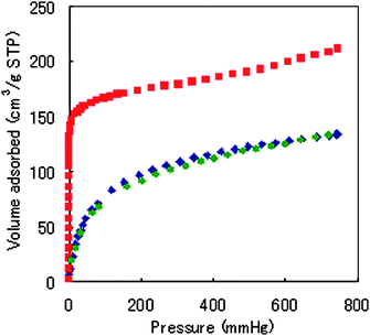
To determine the permanent porosity and capacity of this material for the uptake of gases, we measured the gaseous N2 sorption isotherm on samples of dehydrated R1 at 77.4 K. These sorption isotherms are shown in Fig. 1. The N2 sorption isotherm shows type I behavior, and fitting the data with the Langmuir and Brunauer–Emmett–Teller (BET) equations gave apparent surface areas of 803.9 and 516.5 m2 g−1, respectively. The Langmuir surface area was greater than that of the same motif-type MOFs ([M2(p-BDC)2]n; M = Cu,10Rh,11Mo,12Zn13). Therefore, it is effective to apply the ruthenium ion to the building blocks of the MOFs. After micropore filling, the slope of the volume adsorbed at the isotherm gently rose to saturated pressure. The pore size distribution was obtained by the Horvath–Kawazoe method14 and the pore volume of this material calculated using the Dubinin–Radushkevich (DR) equation from the isotherm were 4.8Å and 0.26 cm3 g−1, respectively.
 | ||
Fig. 1 Adsorption isotherm plot of R1 at 77.4 K ( , N2 adsorption; , N2 adsorption;  , H2 adsorption; , H2 adsorption;  , H2 desorption; STP = Standard Temperature Pressure). , H2 desorption; STP = Standard Temperature Pressure). | ||
The shape of the low-pressure H2 adsorption and desorption isotherm at 77.4 K, shown in Fig. 1, is typical for their kind. R1 could take up H2 equivalent to 133.8 cm3/g STP or 1.2 wt%15 at 760 mmHg. This amount of H2 adsorption was a tempting value as a two-dimensional grid sheet structure. The observed hysteresis in the H2 adsorption and desorption curves indicated that the desorption isotherm is lower than that of the adsorption. Therefore, H2 was physically adsorbed on R1.
To confirm that our synthesized Ru–MOFs function as activity sites for the photochemical reduction of H2O into H2, we initially tested the reduction of aqueous solution (10 ml) in the presence of EDTA–2Na (150 mM) as a sacrificial donor with R1 (0.4 mmol) under UV irradiation (longer than 320 nm) at 300 K in a heterogeneous reaction system. However, under these conditions, no H2 gas was detected even after 24 h of irradiation.
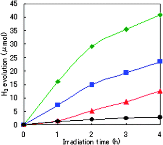
Next, to harvest light efficiently, Ru(bpy)32+ as a photosensitizer (ps) and MV2+ (N,N′-dimethyl-4,4′-bipyridinium) as an electron relay were added to the aqueous solution of EDTA–2Na. The photocatalyst powders used were R1, Ru2(CH3COO)4BF4 (R2; formed Ru2 paddlewheel motif structure, as in Scheme 1),16 and [RuII,III2(p-BDC)2BF4]n (R3; similar formed structure of R1).9d, 20 See Notes for the measurement method we used. As soon as visible light (longer than 420 nm) was irradiated, H2 evolution was observed on R1–R3. Fig. 2 shows the time course of H2 evolution on the R1–R3 and anatase-type TiO2 semiconductor (BET surface area: 40.0 m2 g−1) in the presence of Ru(bpy)32+, MV2+, and EDTA–2Na. The TON (turnover numbers), as one of several measurement conditions 1 and 4 h after the photoirradiation, are listed in Table 1.
| Run | Cat.a | Ru(bpy)32+ (mM) | MV2+ (mM) | λ b (nm <) | Time (h) | TON based on catalyst | TON based on Ru(bpy)32+ |
|---|---|---|---|---|---|---|---|
| a Cat. = catalyst; all catalyst was used 0.01 mmol. b irradiation wavelength. c anatase-type TiO2. | |||||||
| 1 | R1 | 0.1 | 5.0 | 420 | 1 | 3.22 | 32.2 |
| 2 | R1 | 0.1 | 5.0 | 420 | 4 | 8.16 | 81.6 |
| 3 | R1 | 0.1 | 0 | 420 | 4 | 0 | 0 |
| 4 | R1 | 0 | 5.0 | 420 | 4 | 0 | 0 |
| 5 | R1 | 0.1 | 5.0 | — | 4 | 0 | 0 |
| 6 | R2 | 0.1 | 5.0 | 420 | 1 | 0.32 | 3.16 |
| 7 | R2 | 0.1 | 5.0 | 420 | 4 | 2.52 | 25.2 |
| 8 | R3 | 0.1 | 5.0 | 420 | 1 | 1.47 | 14.7 |
| 9 | R3 | 0.1 | 5.0 | 420 | 4 | 4.7 | 47.0 |
| 10 | TiO2 c | 0.1 | 5.0 | 420 | 4 | 0.57 | 5.66 |
| 11 | — | 0.1 | 5.0 | 420 | 1 | 0 | 0 |
 | ||
Fig. 2 Time course of H2 evolution from 10 ml water solution after irradiation started under 0.1 mM Ru(bpy)3Cl2/ 5.0 mM MV2+/ 150 mM EDTA–2Na/ 0.01 mmol photocatalyst condition ( , R1; , R1;  , R2; , R2;  , R3; , R3;  , anatase-type TiO2). , anatase-type TiO2). | ||
The initial slopes of H2 evolution for the three photocatalysts (R1–R3) were measured to be 16.1 µmol h−1 for R1, 1.58 µmol h−1 for R2, and 7.33 µmol h−1 for R3.
The evolution rate of H2 increased as follows: R2 < R3 < R1. Prolonged irradiation led to increased H2 production, up to 41 µmol H2 evolution with 8.16 TON based on R1 and 81.6 based on Ru(bpy)32+ achieved after 4 h irradiation. The apparent quantum yield of R1 was 4.82% at 450 nm. Thus, the catalytic reaction showed evidence of a catalytic cycle with good efficiency. For example, the amount of hydrogen molecules produced after 4 h irradiation by 1.0 g of R1 was 0.14 mol; the activity was 14.4 times greater than that of equal molar anatase-type TiO2 semiconductor photocatalyst in the same system (Run 10) 21
The activities of R1 and R3 (porous material) were far superior to that of R2 (non-porous material). Therefore, forming a porous coordination structure was valuable for improving the activity of the photochemical water reduction. The RuII2 paddlewheel motif more effectively influenced the catalytic activity than did that of RuII,III2 because of the activity of R1 was 1.7 times greater (after 4 h of photolysis) than was that of R3.
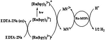
Several control experiments were performed in these heterogeneous systems. As expected, no H2 generation was detected in the dark (Run 4). In addition, if any one of Ru(bpy)32+, MV2+, Ru-MOFs (Runs 3,4 and 11), and EDTA–2Na was omitted from the reaction system, no H2 evolution was detected. Therefore, their promoters are essential for the reduction of water using R1–R3. When 1 equiv. of pyridine was added to the systems, no potential effect on photocatalytic activity was observed. The results of the control experiments indicate Scheme 2 that the H2 evolution in the present system is indeed photoinduced via the excited state of Ru(bpy)32+, the electron relay for MV2+, catalyzed by the Ru–MOFs, and the reduction of Ru(bpy)33+ by EDTA–2Na.
 | ||
| Scheme 2 The reaction scheme of photochemical hydrogen production from water using Ru–MOFs in the presence of Ru(bpy)32+, MV2+, and EDTA–2Na. | ||
In conclusion, we demonstrated that our porous Ru–MOFs were catalyzed at the activity site of the reduction of water into hydrogen molecules in the presence of Ru(bpy)32+, MV2+, and EDTA–2Na. The turnover number was 8.16 based on Ru–MOFs and 81.6 based on Ru(bpy)32+ after 4 h of light irradiation. This is the first example in which MOFs function as activity sites for the photochemical reduction of water into hydrogen molecules. Extensive studies are now in progress in our laboratory.
Notes
Photocatalytic reaction
All photocatalytic reactions were carried out in a closed gas circulation system with a Pyrex reaction cell. The reaction solution was irradiated at 300 K using a Xe lamp equipped with an optical cut-off filter (λ > 420 nm). The amount of H2 evolution was determined by using a gas chromatograph (Shimadzu; GC-14B, with a TCD and FID detector, a molecular sieves 5A column, ultra-pure Ar carrier gas). The reaction solution (10 ml) containing EDTA–2Na (150 mM), Ru(bpy)3Cl2 (0.1 mM), MV2+ (5.0 mM), and Ru–photocatalyst (0.01 mmol)17 was irradiated at 300 K. Measurements were performed under non-oxygen conditions for all photocatalytic reactions. The apparent quantum yield (AQY)18 defined by the following equation was measured using filters combined with a bandpass and cut-off filter (Kenko; 450 nm) and a photodiode (PM3; Coherent).AQY = (number of reacted electrons) / (number of incident photons) × 100 = (number of evolved H2 molecules) × 2 / (number of incident photons) × 100.
(The number of incident photons was 8.81 × 10⁻⁵).
Measurement of gas adsorption
Adsorption was measured with an ASAP2010 volumetric adsorption analyzer. As before treatment, a sample was dried overnight under high vacuum at 300 K and for 1 h at 373 K to remove any solvated water. In the measurements and before treatment, ultra-high-purity grades (99.9999%) of H2, N2 (analysis gas; adsorbent gas), and He (analysis gas for free space) were used.Acknowledgements
This work was supported by a Grant-in-Aid for Specially Promoted Research (No. 19350077) and the High-Tech Research Center Project from the Ministry of Education, Culture, Sports, Science and Technology of Japan. We acknowledge T. Miyao (Yamanashi University) for many valuable conversations and K. Sakai, S. Masaoka, and co-workers (Kyusyu University) for their advice on the instruments used in photocatalytic reactions.References
- (a) E. Borgarello, J. Kiwi, E. Pelizzetti, M. Visca and Michael Gratzel, J. Am. Chem. Soc., 1981, 103, 6324 CrossRef CAS; (b) H. Ozawa, M. Haga and K. Sakai, J. Am. Chem. Soc., 2006, 128, 4926 CrossRef CAS; (c) L. Sun, L. Hammarstrom, B. Akermark and S. Styring, Chem. Soc. Rev., 2001, 30, 36 RSC; (d) K. Maeda, K. Teramura, D. Lu, T. Takata, N. Saito, Y. Inoue and K. Domen, Nature, 2006, 440, 295 CrossRef CAS.
- S. Fukuzumi, Eur. J. Inorg. Chem., 2008, 1351 CrossRef CAS and the references within.
- H. Kato, K. Asakurra and K. Kudo, J. Am. Chem. Soc., 2003, 125(10), 3082 CrossRef CAS.
- (a) T. Sato, W. Mori, C. N. Kato, T. Ohmura, T. Sato, K. Yokoyama, S. Takamizawa and S. Naito, Chem. Lett., 2003, 32(9), 854 CrossRef CAS; (b) S. S. Kaye, A. Dailly, O. M. Yaghi and J. R. Long, J. Am. Chem. Soc., 2007, 129(46), 14177; (c) Kenji Seki, Chem. Commun., 2001, 16, 1946 Search PubMed; (d) H. Li, M. Eddaoudi, M. O'Keeffe and O. M. Yaghi, Nature, 1999, 402, 276 CrossRef CAS.
- (a) C. N. Kato, M. Hasegawa, T. Sato, A. Yoshizawa, T. Inoue and W. Mori, J. Catal., 2005, 230, 226 CrossRef CAS; (b) O. Ohmori and M. Fujita, Chem. Commun., 2004, 1586 RSC.
- (a) A. Kondo, H. Noguchi, L. Carlucci, D. M. Proserpio, G. Ciani, H. Kajiro, T. Ohba, H. Kanoh and K. Kaneko, J. Am. Chem. Soc., 2007, 129(41), 12363; (b) S. Takamizawa, E. Nakata, H. Yokoyama, K. Mochizuki and W. Mori, Angew. Chem., Int. Ed., 2003, 42, 4331 CrossRef CAS; (c) K. Uemura, Y. Yamazaki, Y. Komagawa, K. Tanaka and H. Kita, Angew. Chem., Int. Ed., 2007, 46, 6662 CrossRef CAS.
- W. Mori, F. Inoue, K. Yoshida, H. Nakayama, S. Takamizawa and M. Kishita, Chem. Lett., 1997, 26(12), 1219 CrossRef.
- (a) K. Seki, S. Takamizawa and W. Mori, Chem. Lett., 2001, 30(4), 332 CrossRef; (b) W. Mori, S. Takamizawa, C. N. Kato, T. Ohmura and T. Sato, Microporous Mesoporous Mater., 2004, 73, 31 CrossRef CAS.
- (a) S. Takamizawa, K. Yamaguchi and W. Mori, Inorg. Chem. Acta, 1998, 283, 268 CrossRef CAS; (b) S. Takamizawa, T. Ohmura, K. Yamaguchi and W. Mori, Mol. Cryst. Liq. Cryst., 2000, 342, 199 CrossRef CAS; (c) W. Mori and S. Takamizawa, J. Solid State Chem., 2000, 153, 120 CrossRef; (d) T. Ohmura, W. Mori, H. Hiraga, M. Ono and Y. Nishimoto, Chem. Lett., 2003, 32(5), 468 CrossRef CAS.
- K. Seki, S. Takamizawa and W. Mori, Chem. Lett., 2001, 30(2), 122 CrossRef.
- S. Naito, T. Tanibe, E. Saito, T. Miyao and W. Mori, Chem. Lett., 2001, 1178 CrossRef CAS.
- S. Takamizawa, W. Mori, M. Furihata, S. Takeda and K. Yamaguchi, Inorg. Chem. Acta, 1998, 283, 268 CrossRef CAS.
- H. Li, M. Eddaoudi, T. L. Groy and O. M. Yaghi, J. Am. Chem. Soc., 1998, 120, 8571 CrossRef CAS.
- G. Horvath and K. Kawazoe, J. Chem. Eng. Jpn., 1983, 16, 470 CrossRef.
- The measured hydrogen uptake in cm3/g STP was converted to weight percent by multiplying by a factor of 0.009.
- M. C. Barral, R. J-Aparicio, J. L. Priego, E. C. Royer, E. G-Puebla and C. R-Valero, Polyhedron, 1992, 11, 2209 CrossRef CAS.
- The chemical formula unit is per one ruthenium ion unit.
- It assumed that all of the incident photons were absorbed by the reaction solution.
- Elemental analysis, % obs. (Calc. for [Ru2(p-BDC)2(H2O)4.5]n): C: 31.34 (31.43); H: 2.78 (2.80).
- Elemental analysis, % obs. (Calc. for [Ru2(p-BDC)2BF4(H2O)4]n): C: 28.18 (27.88); H: 2.81 (2.34).
| This journal is © The Royal Society of Chemistry 2009 |
