Dye-sensitized solar cells based on low cost nanoscale carbon/TiO2 composite counter electrode
Prakash
Joshi
a,
Yu
Xie
a,
Mike
Ropp
a,
David
Galipeau
a,
Shelia
Bailey
b and
Qiquan
Qiao
*a
aCenter for Advanced Photovoltaics, South Dakota State University, Brookings, SD 57007, USA. E-mail: Qiquan.Qiao@sdstate.edu.; Fax: +1 605 688 4401; Tel: +1 605 688 6965
bNASA Glenn Research Center, 21000 Brookpark Road, Cleveland, OH 44135, USA. Fax: +1 216 433 6106; Tel: +1 216 433 2228
First published on 2nd March 2009
Abstract
A dye-sensitized solar cell based on low cost nanoscale carbon/TiO2 composite counter electrode was fabricated and its photovoltaic performance (η = 5.5%, AM 1.5, 91.5 mW cm−2) was comparable to that from platinum counter-electrode devices (η = 6.4%, AM 1.5, 91.5 mW cm−2) made at similar conditions.
Broader contextPhotovoltaics (PV) currently provides less than 0.1% of the world's energy needs and are only expected meet about 2% of world needs in 20 years at the current annual growth rate. This limited contribution is a result of the high cost of silicon solar cells due to the need for high-purity silicon and high temperature processing. Almost 90% of the existing PV market is based on silicon cells but unfortunately, after more than 50 years of development, further breakthroughs in Si PV appear less likely. Dye-sensitized solar cells (DSSCs) have evolved as a potential alternative to Si PV. Typical DSSCs consist of TiO2 anode electrode, dyes, electrolytes, and platinum counter-electrode. This paper reports the use of inexpensive nanoscale carbon/TiO2 composite in place of platinum as the counter electrode to further reduce the cost for DSSCs. The performance of cells based on the nanoscale carbon/TiO2 composite counter electrode is comparable to that of platinum based devices fabricated at similar conditions. |
Introduction
Direct conversion of sunlight into electricity using solar cells is a steadily growing energy technology which is gaining tremendous popularity because they can produce electricity near the end user, avoiding transmission losses and costs. The solar panels operate without noise, toxicity, or greenhouse gas emissions. However, due to the high material and fabrication cost in Si solar cells, the PV electricity generated is less than 0.1% of the total energy demand of the world. Dye-sensitized solar cells (DSSCs) have the potential to be a low-cost alternative to silicon solar cells due to their low cost and high power conversion efficiency.1–8Dye-sensitized solar cells are made of two transparent conducting glasses, one of which is a photoanode coated with porous nanocrystalline TiO2 and the other is a counter electrode coated with a catalyst. Dye molecules are attached onto the surface of the nc-TiO2 and an electrolyte containing a redox couple (I−/I3−) is filled between the photoanode and counter electrode. Dye molecules absorb light and inject electrons into the conduction band of TiO2. The electron passes through the porous nanocrystalline TiO2 to the transparent conducting oxide layer and then goes along an external load to the counter electrode, where it is transferred to tri-iodide to yield iodide according to I3− + 2e− → 3I−. When iodide (I−) diffuses to dye sensitized porous TiO2electrode, it reduces the oxidized dyes (S+) following 2S+ + 3I− → 2S + I3−. In order for sufficiently fast reaction kinetics in tri-iodide reduction, a thin platinum film was deposited onto the counter electrode as a catalystviaspin coating,9sputtering,10electrochemical deposition,11 or themolysis method.12 Though platinum is a very efficient catalyst towards tri-iodide reduction,13platinum has the disadvantage of being very expensive. As a thin layer of platinum is enough for tri-iodide reduction, the amount of platinum needed for a DSSC is small (about 50 mg m−2).14 However, the commercial mass production of DSSCs will still need a large amount of platinum which is not abundantly available. Therefore, efforts are needed to search for an alternative material which is readily available, cost effective, and capable of showing comparable catalytic effects for tri-iodide reduction, and carbon is such a material. Recently several groups have focused on carbon which is deposited by a doctor blading method.14–16 The thicknesses of doctor bladed carbon counter electrodes need to be as thick as several tens of micrometers to be comparable to a platinum counter electrode. Such a thick doctor bladed carbon counter electrode increases the device internal resistance and thus hinders device performance by reducing the fill factor.15,17
In this work, we report efficient dye-sensitized solar cells using low cost carbon/TiO2 composite as an alternative to platinum as a counter-electrode catalyst for tri-iodide reduction. In the carbon/TiO2 composite, carbon acts as a catalyst and the TiO2 functions as a binder. The paste that we prepared using nanoscale carbon/TiO2 composite for the counter electrodes can be deposited by spin coating or doctor blading. The carbon/TiO2 composite counter electrodes were developed using a spin coating processing. The results showed that device performance in terms of short circuit current density (JSC), open circuit voltage (VOC), and energy conversion efficiency (η) from carbon/TiO2 composite cells were comparable to those from platinum devices.
Experimental
Carbon nanoparticles were purchased from Sigma-Aldrich with a particle size <50 nm and a surface area >100 m2 g−1. A weight of 650 mg carbon nanoparticles was mixed with 1 ml TiO2 colloid paste at a concentration of 20% by weight. The TiO2 colloid paste was made by dispersing P25 Degussa TiO2nanoparticles (average size of 25 nm) into water. The TiO2nanoparticles were used as a binder not only to connect carbon nanoparticles together but also to bind the carbon catalyst layer to the counter FTO. Then 2 ml deionized (DI) water was added to the mixture. The mixture was then ground in a mortar by adding 1 ml Triton X-100 aqueous solution. Afterwards, the paste was sonicated for an hour. The counter electrode was then made by spin coating the paste onto the fluorine-doped tin dioxide (FTO, purchased from Hartford Glass Co.) substrate with a FTO thickness of ∼400 nm and a sheet resistance of 8 Ω square−1. The dried carbon layer was then sintered at 250 °C for an hour. DSSCs were fabricated using Z-907 dye, which was received from Konarka Technologies.Scanning electron microscopy (SEM) images were obtained using a Zeiss Supra 40VP field-emission scanning electron microscope.
Results and discussion
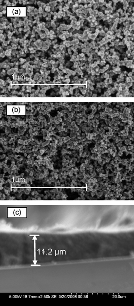
Fig. 1a and b show the top view SEM images of carbon/TiO2 composite and pure TiO2nanoparticle films. A highly porous carbon/TiO2 composite counter-electrode as a catalyst layer is shown in Fig. 1a. The high surface area of these electrodes, caused by the carbon/TiO2nanoparticles, helps them to function effectively for tri-iodide reduction. The size of the pores ranges from 20 nm to 200 nm throughout the films, indicating that I3− ions with a size of only a few angstroms can easily diffuse into the pores and get reduced at the carbon nanoparticle surface.15 The particle sizes in carbon/TiO2 composite (Fig. 1a) film are apparently larger than those in pure TiO2nanoparticle films (Fig. 1b). This indicates that the carbon nanoparticle dominates in the carbon/TiO2 mixture and would effectively serve as a catalyst for tri-iodide reduction. A cross-section SEM image (Fig. 1c) shows a carbon/TiO2 composite counter electrode layer with a thickness of about 11.2 um. | ||
| Fig. 1 Top view SEM images of (a) a 11.2 um thick carbon/TiO2 composite layer and (b) a pure TiO2nanoparticle layer on a FTO substrate. Cross section SEM image of (c) a carbon/TiO2 composite layer. | ||
Using electrochemical impedance spectroscopy (EIS), Ramasamy et al. observed that the charge transfer resistance of the carbon electrode in liquid electrolyte was much lower than that of the screen printed platinum.15 The lower charge transfer resistance counterbalances the high internal series resistance of the carbon device. Series resistance of carbon/TiO2 composite based DSSCs was also studied in comparison with platinum based devices using multiple light intensities.
Current density (JSC) through the series resistance is as below:18
 | (1) |
This equation can be modified as:
 | (2) |
When we plot current density–voltage (J–V) curves at multiple light intensities and select the points of (J,V) which satisfy the following condition:
| JPH − J = ΔJ = constant | (3) |
The points should lie in the straight line and follow:
| J = V/RsA + constant | (4) |
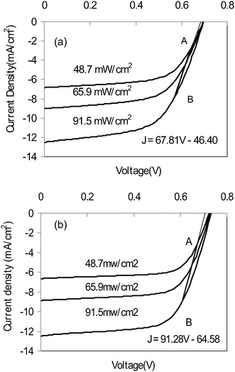
From eqn 4, series resistance of DSSCs can be determined from the slope of the straight line. Fig. 2a and b show the J–V curves from DSSC devices at different light intensities with carbon/TiO2 composite (Fig. 2a) and platinum (Fig. 2b) counter electrode.
 | ||
| Fig. 2 Calculation of series resistance from J–V curves of DSSC devices at different light intensity using (a) carbon/TiO2 composite counter electrode and (b) platinum counter electrode. | ||
The active areas for carbon/TiO2 composite and platinum based devices are 0.20 cm2 and 0.24 cm2, respectively. AB is the straight line described by eqn 4. Its slope in carbon/TiO2 composite devices is 67.81 mA (cm2V)−1 (Fig. 2a), with a reciprocal of 14.75 Ωcm2 and a series resistance of 73.74 Ω; while that in platinum based devices is 91.28 mA (cm2V)−1 (Fig. 2b) with a reciprocal of 11.37 Ωcm2 and a series resistance of 45.67 Ω. It can be seen that the series resistance of carbon/TiO2 composite based devices is higher than that of platinum based devices. The possible reason is that the carbon/TiO2 composite counter electrode has much higher thickness and resistivity than those of platinum.17 However, the advantage of a carbon/TiO2 composite counter electrode is its nanostructured large inner electrode surface area. This results in a lower charge transfer resistance (RCT). A value of RCT in a carbon electrode was observed to be less than half of that in a platinum electrode.15 The low RCT would compensate for the effects of higher series resistance and help to achieve an overall photovoltaic performance in carbon/TiO2 composite devices comparable to that of a platinum based device.
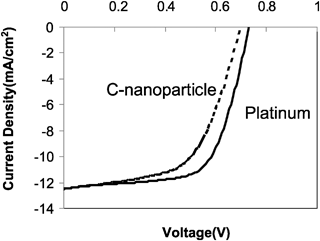
Fig. 3 shows a comparison of current density versus voltage (J–V) curves from carbon/TiO2 composite and platinum based DSSCs under illumination from an AM 1.5 solar simulator at an intensity of about 91.5 mW cm−2. DSSCs with carbon/TiO2 composite counter electrode achieve an overall light to electric energy conversion efficiency of 5.5%, which is comparable to 6.4% of platinum counter electrode devices. The photovoltaic parameters in terms of short circuit current density (JSC), open circuit voltage (VOC), and energy conversion efficiency (η) are listed in Table 1. The FF of carbon/TiO2 composite devices was found to be slightly lower than platinum based devices. This may be attributed to the higher series resistance (73.74 Ω) in a carbon/TiO2 composite device compared to that (45.65 Ω) in a platinum based device. The stability of carbon based DSSCs using a different dye was studied by Ramasamy et al.15 and the results showed a comparable stability as platinum based devices.
| Counter electrodes | J SC/mA cm−2 | V OC/V | FF | η | R s (Ω) |
|---|---|---|---|---|---|
| Carbon/TiO2 composite | 12.53 | 0.70 | 0.57 | 5.5% | 73.74 |
| Platinum | 12.48 | 0.73 | 0.65 | 6.4% | 45.65 |
 | ||
Fig. 3
I–V curves of DSSCs with carbon/TiO2 composite (![[dash dash, graph caption]](https://www.rsc.org/images/entities/char_e091.gif) ) and platinum ( ) and platinum (![[thick line, graph caption]](https://www.rsc.org/images/entities/char_e117.gif) ) counter electrodes under one sun illumination AM 1.5 with a light intensity of 91.5 mW cm−2. Active areas of carbon/TiO2 composite and platinum counter electrode device are 0.20 cm2 and 0.24 cm2, respectively. ) counter electrodes under one sun illumination AM 1.5 with a light intensity of 91.5 mW cm−2. Active areas of carbon/TiO2 composite and platinum counter electrode device are 0.20 cm2 and 0.24 cm2, respectively. | ||
Conclusion
In summary, we have successfully developed a low cost DSSC with a solar to electric energy conversion efficiency of about 5.5% using a carbon/TiO2 composite as the counter electrode and a stable Ru complex dye (Z-907) as the sensitizer. The carbon/TiO2 composite was made using a spin coating fabrication processing, which can be modified to screen printing processing. These cells have shown a comparable device performance in terms of short circuit current density (JSC), open circuit voltage (VOC), and energy conversion efficiency (η) to those based on platinum counter electrode at similar fabrication conditions. In addition, the series resistance of carbon/TiO2 composite DSSCs was found to be a little higher than that of platinum based cells, leading to a slightly lower FF. Therefore, the carbon/TiO2 composite showed significant potential as a low cost alternative to currently widely-used, expensive platinum.Acknowledgements
The authors would like to acknowledge the South Dakota NSF EPSCoR program and South Dakota NASA EPSCoR program for financial support. The authors would also like to acknowledge Dr Hao Fong and Dr Lifeng Zhang for the assistance with SEM images. In addition, the authors would like to thank Dr Mahdi Farrokh Baroughi for the I–V curve measurement.References
- B. Oregan and M. Gratzel, Nature, 1991, 353, 737–740 CrossRef CAS.
- M. Gratzel, J. Sol–Gel Sci. Technol., 2001, 22, 7–13 CrossRef.
- B. A. Gregg, A. Zaban and S. Ferrere, Z. Phys. Chem.: Int. J. Res. Phys. Chem. Chem. Phys., 1999, 212, 11–22 Search PubMed.
- G. P. Smestad, Sol. Energy Mater. Sol. Cells, 2003, 76, 1–2 CrossRef CAS.
- J. Nelson, S. A. Haque, D. R. Klug and J. R. Durrant, Phys. Rev. B: Condens. Matter Mater. Phys., 2001, 63, 205321 CrossRef.
- M. K. Nazeeruddin, S. M. Zakeeruddin, J. J. Lagref, P. Liska, P. Comte, C. Barolo, G. Viscardi, K. Schenk and M. Graetzel, Coord. Chem. Rev., 2004, 248, 1317–1328 CrossRef CAS.
- B. O'Regan, D. T. Schwartz, S. M. Zakeeruddin and M. Gratzel, Adv. Mater., 2000, 12, 1263 CrossRef CAS.
- B. O'Regan, V. Sklover and M. Gratzel, J. Electrochem. Soc., 2001, 148, C498–C505 CrossRef CAS.
- S. Lee, Y. Jun, K.-J. Kim and D. Kim, Sol. Energy Mater. Sol. Cells, 2001, 65, 193–200 CrossRef CAS.
- M. K. Nazeeruddin, A. Kay, I. Rodicio, R. Humphry-Baker, E. Mueller, P. Liska, N. Vlachopoulos and M. Graetzel, J. Am. Chem. Soc., 1993, 115, 6382–6390 CrossRef CAS.
- N. Papageorgiou, W. F. Maier and M. Gratzel, J. Electrochem. Soc., 1997, 144, 876–884 CAS.
- J. M. Kroon, N. J. Bakker, H. J. P. Smit, P. Liska, K. R. Thampi, P. Wang, S. M. Zakeeruddin, M. Grätzel, A. Hinsch, S. Hore, U. Würfel, R. Sastrawan, J. R. Durrant, E. Palomares, H. Pettersson, T. Gruszecki, J. Walter, K. Skupien and G. E. Tulloch, Prog. Photovoltaics, 2007, 15, 1–18 CAS.
- X. M. Fang, T. L. Ma, G. Q. Guan, M. Akiyama and E. Abe, J. Photochem. Photobiol., A, 2004, 164, 179–182 CrossRef CAS.
- T. N. Murakami, A. Kay, S. Ito, Q. Wang, M. K. Nazeeruddin, T. Bessho, P. Liska, R. H. Baker, P. Comte, P. Péchy and M. Graetzel, J. Electrochem. Soc., 2006, 153, A2255–A2261 CrossRef CAS.
- E. Ramasamy, W. J. Lee, D. Y. Lee and J. S. Song, Appl. Phys. Lett., 2007, 90, 173103 CrossRef.
- K. Imoto, M. Suzuki, K. Takahashi, T. Yamaguchi, T. Komura, J. Nakamura and K. Murata, Electrochemistry, 2003, 71, 944–946 CAS.
- K. Imoto, K. Takahashi, T. Yamaguchi, T. Komura, J. Nakamura and K. Murata, Sol. Energy Mater. Sol. Cells, 2003, 79, 459–469 CrossRef CAS.
- T. Matsubara, R. Sakaguchi, H. Nagai, K. Aramaki and A. Katagiri, Electrochemistry, 2005, 73, 60–66 CAS.
| This journal is © The Royal Society of Chemistry 2009 |
