Phenylene-bridged hybrid silica spheres for high performance liquid chromatography†
Yongping
Zhang
a,
Yu
Jin
a,
Peichun
Dai
a,
Hui
Yu
a,
Danhua
Yu
a,
Yanxiong
Ke
*a and
Xinmiao
Liang
*ab
aSchool of Pharmacy, Engineering Research Center of Pharmaceutical Process Chemistry, Ministry of Education, East China University of Science and Technology, 130 Meilong Road, Shanghai, 200237, China. E-mail: liangxm@dicp.ac.cn; Fax: +86 021-64250622; Tel: +86 021-64250622; key@ecust.edu.cn; Fax: +86 411-84379539; Tel: +86 411-84379519
bDalian Institute of Chemical Physics, Chinese Academy of Sciences, 457 Zhongshan Road, Dalian, 116023, China
First published on 30th September 2009
Abstract
Highly monodisperse 1,3-phenylene-bridged hybrid organosilica spheres (m-PHS) were synthesized by co-condensation of tetraethoxysilane (TEOS) and 1,3-bis(triethoxysilyl)benzene (1,3-BTEB) using dodecylamine (DDA) and cetyltrimethylammonium bromide (CTAB) as templates. In this method, three important factors are the surfactants, the ethanol–water volume ratio and the TEOS/1,3-BTEB molar ratio. Their effects on the spherical particle morphologies were investigated systematically to optimize the synthesis conditions. With the optimal method, m-PHS was prepared with uniform particles in a narrow range 1.8∼2.5 µm. Likewise, highly monodisperse 1,4-phenylene-bridged hybrid organosilica spheres (p-PHS) were synthesized from TEOS and 1,4-bis(triethoxysilyl)benzene (1,4-BTEB) to compare the chromatographic properties with m-PHS. Both two hybrid materials can be directly used for reversed-phase high-performance liquid chromatography (RP-HPLC), showing high column efficiency, and the m-PHS stationary phase exhibits a much longer retention time and better separation ability for some aromatic compounds.
Introduction
Spherical hybrid organosilica spheres have attracted much research interest in the separation field. Compared with mesoporous silicas, the hybrid organosilica materials exhibit excellent hydrothermal, chemical and mechanical stability, which means that the packings are more durable under adverse conditions.1–6 Moreover, the direct incorporation of organic groups into the silica framework also provides a new synthetic method for the chromatographic stationary phase.7–9The ideal HPLC packing should have a uniform spherical shape and narrow particle size distribution, which is essential to achieve high column efficiency.10 However, most reports have described the synthesis of hybrid organosilica materials with powder and thin film morphology; few reports have investigated the preparation of monodisperse spherical particles. This indicates that it is still a challenge to control both surface properties and morphologies.11,12
Recently, the direct employment of 1,4-phenylene-bridged hybrid organosilica spheres for normal phase-HPLC packing was reported by Fröba and co-workers.7 The special chromatographic separation results demonstrated the potential application of phenylene-bridged hybrid organosilica spheres for HPLC, however, the particle size distributions of the materials were in the relatively broad range between 3 and 15 µm. Zhong et al. have described the synthesis of a mesoporous phenylene-bridged hybrid monolith used as a stationary phase for HPLC from 1,4-bis(triethoxysilyl)benzene (1,4-BTEB) and tetraethoxysilane (TEOS).13 Although there are many reports on mesoporous phenylene (–C6H4–) hybrid organosilicas,14–19 the synthesis of highly monodisperse spheres with narrow particle size are rare, and reports concerning synthesis and application in HPLC separation are limited. In addition, phenylene-bridged hybrid organosilicas with different substituted benzene sites will possess different surface properties, for instance, 1,3-phenylene-bridged and 1,4-phenylene-bridged16 perhaps would induce different chromatographic separation performances for HPLC. Therefore, the development of a synthetic strategy and research on their chromatographic properties are still required.
In this study, we report the synthesis of highly monodisperse 1,3-phenylene-bridged and 1,4-phenylene-bridged hybrid organosilica spheres with narrow particle distributions in the range of 1.8∼2.5 µm. Columns packed with these materials can be directly used as stationary phases for reversed-phase HPLC to separate aryl compounds with high column efficiency. The different chromatographic separation behaviors of 1,3-phenylene-bridged and 1,4-phenylene-bridged hybrid materials were also investigated in this study.
Experimental
Chemicals
1,3-bis(Triethoxysilyl)benzene (1,3-BTEB) and 1,4-bis(triethoxysilyl)benzene (1,4-BTEB) were purchased from Aldrich. N,N-Dimethyldecylamine (DMDA) was purchased from TCI. Dodecylamine (DDA), cetyltrimethylammonium bromide (CTAB) and tetraethylorthosilicate (TEOS) were purchased from ShangHai Chemical Reagent Inc. of Chinese Medicine Group. Other chemicals were commercially available and used as received.Synthesis of phenylene-bridged silica spheres
The samples S1–S8 and corresponding initial gel compositions are listed in Table 1. In a typical synthesis of sample S3, DDA (6.67 g, 36.0 mmol) and CTAB (0.67 g, 1.8 mmol) were dissolved in 1000 mL of ethanol–water (35:65 = v/v). To this solution, 0.8 mL of NH4OH (25 wt % solution) were added. Then, the mixture of 1,3-BTEB (8.04 g, 20 mmol) and TEOS (19.1 g, 92 mmol) was added to the solution and vigorously stirred for 1 min at 25 °C. After aging for 12 h in static conditions at 25 °C, the white precipitate was filtered out and washed twice with ethanol, and dried in air.| Samples | 1,3-BTEB/TEOS (mmol) | DDA/CTAB (mmol) | EtOH/H2O(mL) | NH4OH (25 wt %, mL) |
|---|---|---|---|---|
| a Sample S8 was synthesized by condensation of 1,4-BTEB and TEOS. | ||||
| S1 | 20/92 | 37.8/0 | 650/350 | 0.80 |
| S2 | 20/92 | 0/37.8 | 650/350 | 0.80 |
| S3 | 20/92 | 36.0/1.80 | 650/350 | 0.80 |
| S4 | 20/92 | 36.0/1.80 | 700/300 | 0.80 |
| S5 | 20/92 | 36.0/1.80 | 600/400 | 0.80 |
| S6 | 12/100 | 36.0/1.80 | 650/350 | 0.80 |
| S7 | 56/56 | 36.0/1.80 | 650/350 | 0.80 |
| S8a | 20/92 | 36.0/1.80 | 650/350 | 0.80 |
For post-synthesis of pore expansion, 2 g of as-prepared dry solid S3 was added to an emulsion of DDA (0.4 g), DMDA (2.0 g) and water (80 mL). After about 30 min of stirring at room temperature, the mixture was transferred into a Teflon-coated autoclave and hydrothermally treated at 135 °C for 12 days. The product was filtered out and extracted twice with ethanol and HCl (5.0 mL) of 2 M HCl in 150 mL of ethanol at 80 °C for 12 h to remove the structure directing agents. This material was denoted as m-PHS. The product from sample S8 after the same post-synthesis procedure was denoted as p-PHS.
Characterization
X-ray powder diffraction (XRD) patterns were recorded on a Rigaku D/Max 2550 power diffraction system using Cu Kα radiation. Nitrogen adsorption and desorption isotherms were taken on a ASAP2100 apparatus. The samples were degassed at 150 °C under vacuum overnight prior to measurements. Surface areas and pore-size distributions were measured using the BET and BJH methods, respectively. Scanning electron micrographs (SEM) were obtained on a JSM-6360LV instrument. Thermogravimetric analysis (TGA) curves were obtained in flowing air on a TGA/SDTA/851e with a heating rate of 10 °C/min. Elemental analyses were performed using a Vario EL III analyzer. The solid-state spectra were recorded on a DSX 300 spectrometer (sample spinning frequency of 4.2 kHz; π/2 pulse width of 6 ms). The solid-state 13C cross-polarization magic angle spinning (CP-MAS NMR) spectra were obtained under the conditions of a 1 ms contact time, a 2 s recycle delay and 1700 scans, and 29Si CP-MAS NMR measured under the conditions of a 5 ms contact time, a 3 s recycle delay and 880 scans.Chromatography
The materials m-PHS and p-PHS were each dispersed into acetone and packed into a stainless-steel column (50 mm × 2.1 mm I.D.) by a slurry packing technique. HPLC evaluation was performed using an Agilent HPLC system, which comprised an Agilent 1200 series, G1379B degasser, G1312B pump, G1367C Autosampler, and G1315C diode array detector (DAD). All the test probes were prepared to about 1 mg/mL concentration using methanol. The injected volume was 0.5 µL.Results and discussion
Morphology control of phenylene-bridged hybrid organosilica materials
The synthetic details of the phenylene-bridged hybrid organosilica materials are listed in Table 1. The particle morphologies of materials are shown by the SEM images in Fig. 1.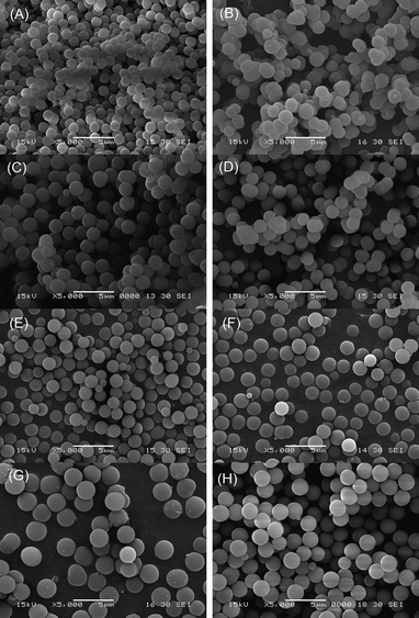 | ||
| Fig. 1 SEM images of (A) sample S1 (synthesized in the presence of only DDA); (B) sample S2 (synthesized in the presence of only CTAB); (C) sample S3 (synthesized in the presence of both DDA and CTAB); (D) sample S4 (synthesized in the ethanol–water volume ratio of 60:40); (E) sample S5 (synthesized in the ethanol–water volume ratio of 70:30); (F) sample S6 (synthesized in the 1,3-BTEB/TEOS molar ratio of 12:100); (G) sample S7 (synthesized in the 1,3-BTEB/TEOS molar ratio of 56:56); (H) sample S8 (synthesized in the 1,4-BTEB/TEOS molar ratio of 20:92). | ||
Using DDA, CTAB or both of them as templates to prepare mesoporous silica spheres has been reported previously.20,21 Here, we studied the influences of these surfactants on the morphologies of phenylene-bridged hybrid materials. Sample S1 synthesized in the presence of only DDA shows a highly monodisperse spherical morphology, but the particle sizes of the spheres are in the range of 1.0∼1.5 µm (Fig. 1(A)). The addition of CTAB as co-surfactant leads to the enlargement of the sphere sizes to the range of 1.8∼2.5 µm (sample S3, Fig. 1(C)). However, most of the particles of sample S2 synthesized in the presence of only CTAB were aggregated together (Fig. 1(B)). These results indicate that it facilitates highly monodispersed spherical phenylene-bridged hybrid organosilica materials with relatively large particle sizes in the presence of both DDA and CTAB as templates.
It has been demonstrated that the ethanol concentration is a crucial factor to control the spherical morphologies of MCM-41 and MCM-48 materials.22 The effects of the ethanol–water volume ratio on the morphologies of phenylene-bridged hybrid silica were investigated. Sample S4 and S5 were obtained under the same conditions as that of sample S3 at the ethanol–water volume ratio of 60:40 and 70:30, respectively. Sample S4 was mainly composed of the monodisperse spheres, but some particle aggregations also exist (Fig. 1(D)). When the ethanol is increased in sample S5, the particle sizes were decreased to the range of 1.5∼2.0 µm (Fig. 1(E)), compared to sample S3. These results show that the ethanol–water volume ratio plays an important role in the formation of highly monodisperse spherical particles and the size control of spheres.
To investigate the influences of the 1,3-BTEB/TEOS molar ratios, sample S6 and S7 were synthesized under the same conditions as that of sample S3 at the 1,3-BTEB/TEOS molar ratio of 12:100 and 56:56, respectively. As shown in the SEM image in Fig. 1(F), the particle sizes of sample S6 are nearly the same as sample S3. With an increase of the molar ratio of 1,3-BETB/TEOS to 56:56, the particle sizes of sample S7 increased to the range of 2.0∼3.0 µm, but some particles have an irregular shape (Fig. 1(G)). The above results indicate that the morphology of the organosilicas can be adjusted by changing the molar ratios of the 1,3-BTEB/TEOS, and a low concentration of 1,3-BTEB is helpful for the formation of spherical morphology.
For comparing the properties of hybrid organosilica materials containing 1,3-phenylene-bridged and 1,4-phenylene-bridged organic groups, sample S8 was synthesized under the same conditions as sample S3 from 1,4-BTEB/TEOS (20:92). Fig. 1(H) shows the SEM image of sample S8. The sample has perfect spherical morphology and good monodispersity with particle sizes of 1.8∼2.5 µm.
The pore size expansion of phenylene-bridged hybrid organosilica materials
The nitrogen adsorption isothermal of as-prepared samples S3 and S8 were of type I (see ESI† ). According to the literature,9,23 the pore diameters of these samples calculated from the adsorption branch by the BJH (Barrett–Joyner–Halenda) method were all less than 1.8 nm. The BET (Brunauer–Emmett–Teller) surface area of S3 was 1022 m2/g, and the total pore volume was 0.57 cm3/g. For sample S8, the BET surface area and the total pore volume were 760 m2/g and 0.41 cm3/g, respectively.The samples m-PHS and p-PHS were obtained from samples S3 and S8 via the hydrothermal treatment using DMDA as swelling agent, respectively. N2 adsorption–desorption isotherms and the corresponding BJH pore size distributions of both m-PHS and p-PHS are shown in Fig. 2. The nitrogen adsorption isothermals of m-PHS and p-PHS are type IV. The pore size distributions of the two samples exhibit a maximum at 4.3 nm for m-PHS and 5.2 nm for p-PHS. The BET surface area of m-PHS is 749 m2/g, which is higher than that of p-PHS (530 m2/g). The pore volumes were found to have increased to 0.63 for m-PHS and 0.72 for p-PHS, respectively. Fig. 3 shows the SEM images of the samples m-PHS and p-PHS. The phenylene-bridged hybrid silica spheres still keep a good spheric morphology and the particle sizes almost remain unchanged after the hydrothermal treatment with DMDA. Sayari et al. have reported that using DMDA as the swelling agent could dramatically expand the pore size of MCM-41 type silica, and the particle swelling was found after the post hydrothermal treatment.23,24 The results found in m-PHS and p-PHS indicate that phenylene-bridged hybrid silicas have much better hydrothermal stability than mesoporous silica. Thermogravimetrical analysis of p-PHS and m-PHS also show that both two samples contain 15–20% amount of organic species (see ESI† ). The lack of any substantial weight loss indicated that the surfactant was successfully removed viasolvent extraction. Both of the two samples show excellent thermal stability higher than 800 K in air conditions.
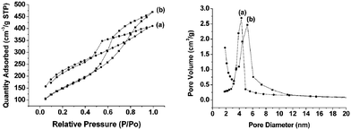 | ||
| Fig. 2 N2 adsorption–desorption isotherms and BJH desorption pore size distribution of (a) m-PHS and (b) p-PHS after hydrothermal treatment. | ||
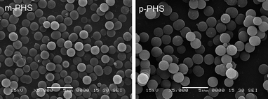 | ||
| Fig. 3 SEM images of phenylene-bridged hybrid silica spheres after hydrothermal treatment. | ||
Chemical composition of the hybrid materials
Elemental analysis results show that the carbon contents of m-PHS and p-PHS are 14.78% and 15.19%, respectively. The similar carbon contents indicate that the two samples have a close content of phenyl group in the pore walls.The integrities of the m-phenylene and p-phenylene groups in the pore wall were further confirmed by solid state 13C CP MAS and 29Si MAS NMR (as shown in Fig. 4). The 13C chemical shifts of p-PHS show only a single carbon peak assigned to the phenylene groups (ca. 133 ppm) covalently linked to Si.13,14 The 13C CP MAS spectra of m-PHS displays four resonances at 140, 135, 130 and 127 ppm in accordance with the four different carbon atoms in 1,3-BTEB.16 The resonances of (a) and (b) at 15 and 59 ppm are from the ethoxy groups formed during the surfactant extraction process. No carbon signals of DDA, CTAB and DMDA were observed in the 13C CP MAS spectra, which indicate that the surfactants and swelling agents were almost completely removed by the solvent extraction. The 29Si MAS NMR spectra of p-PHS are similar to m-PHS, both spectra show the Q sites and T sites. The resonances at −100 and −110 ppm were assigned to Q3[(OH)Si(OSi)3] and Q4[Si(OSi)4], respectively; a relatively weak signal at −62 ppm was assigned to T1[SiO(OH)2SiC]; two strong signals at −70 and −78 ppm correspond to T2[(SiO)2(OH)SiC] and T3[(SiO)3SiC], respectively. These data are in accord with the reported data found in the organosilica materials containing 1,3-phenylene and 1,4-phenylene groups; the strong intensity for T2 and T3 demonstrated the formation of the highly condensed organosilicate frameworks.
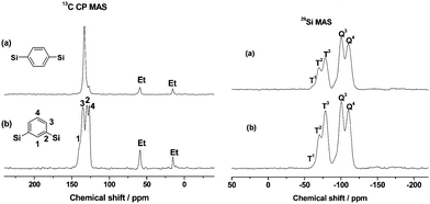 | ||
| Fig. 4 13C CP MAS and 29Si MAS NMR spectra of (a) p-PHS and (b) m-PHS. | ||
Chromatographic evaluation
To evaluate the separation performance, m-PHS and p-PHS were packed into 2.1 × 50 mm columns, respectively. Both columns were subjected to the same chromatographic separation tests. For chromatographic evaluation of the column, m-PHS and p-PHS was performed in acetonitrile/watereluents. Their chromatographic behaviors were investigated with four phenyl compounds as test probes (Fig. 5). The column efficiency is 186,000 plates/m for m-PHS and 126,000 plates/m for p-PHS (both calculated from O-terphenyl on the chromatograms), respectively. The high column efficiency may benefit from the high monodispersity of the organosilica spheres.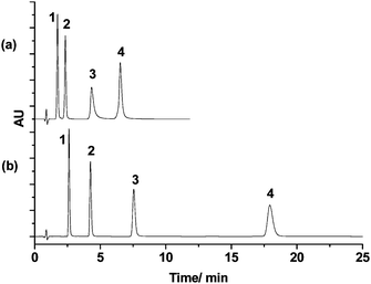 | ||
| Fig. 5 The chromatograms (a) and (b) obtained with the p-PHS column (50 mm × 2.1 mm I.D.) and column m-PHS column (50 mm × 2.1 mm I.D.) respectively. Mobile phase: acetonitrile/water (35/65); flow rate: 0.2 mL min−1; 35 °C; UV: 254 nm. Analytes: 1. Dimethyl phthalate; 2. Diethyl phthalate; 3. Diphenyl; 4. O-terphenyl. | ||
Under the same condition, m-PHS shows a much longer retention time and higher separation efficiency than p-PHS. The retention time of compound O-terphenyl on the column m-PHS (18.1 min) was 2.8 times longer than that of the p-PHS (6.5 min), which may arise not only from the higher surface area of m-PHS but also from the different surface properties of these two materials. 1,4-BTEB has a linear rigid rodlike geometry whereas 1,3-BTEB has a bent structure. They will result in different orientations of the phenylene rings in the pore wall. We suppose that some of the phenylene groups will point to the pore channels in m-PHS, while most of the phenylene groups will reside in the pore wall in p-PHS (Scheme 1). Thus, the π–π interactions between the analytes and the phenyl rings will be stronger in m-PHS than in p-PHS.
 | ||
| Scheme 1 Proposed different orientations of phenylene groups in the pore wall of PHS materials. (a) p-PHS; (b) m-PHS. | ||
The fast separation performance of m-PHS and p-PHS was also investigated. Typical chromatograms with m-PHS and p-PHS are shown in Fig. 6, in which eleven phenyl compounds bearing different groups were successfully separated with both columns in 5 min at 55 °C. This demonstrates good separation selectivity for aromatic compounds in these stationary phases.
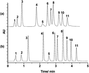 | ||
| Fig. 6 Chromatograms for a mixture of 11 compounds with the (a) p-PHS column (50 mm × 2.1 mm I.D.) and (b) m-PHS column (50 mm × 2.1 mm I.D.). Gradient: 0–4 min, 5%–60% B; 4–5 min, 60% B; mobile phase: A: Water B: acetonitrile; flow rate: 0.5 mL min−1; 55 °C; UV: 254 nm. Analytes: (1) uracil; (2) cytidine; (3) phenol; (4) acetanilide; (5) benzene; (6) acetophenone; (7) (4-methoxyphenyl)ethanone; (8) 1,2-dinitrobenzene; (9) diphenyl ketone; (10) naphthalene; (11) phenanthrene. | ||
Conclusion
In conclusion, highly monodisperse 1,3-phenylene-bridged (m-PHS) and 1,4-phenylene-bridged hybrid organosilica (p-PHS) spheres were successfully synthesized based on a modified Stöber reaction. The results show that the surfactants and ethanol–water volume ratio play an important role for the control of the monodisperse sphere and size distributions. The m-PHS and p-PHS spheres were introduced for use as a stationary phase for reversed-phase HPLC. Both of the two columns show very good column efficiency. Compared with p-PHS, m-PHS exhibits relatively longer retention times and good separation performances under reversed-phase HPLC. This work provides a new strategy for the preparation of phenylene-bridged hybrid organosilica stationary phases for HPLC.Acknowledgements
This work was supported by the NSF of China (Grant No. 20601025).Notes and references
- J. S. Mellors and J. W. Jorgenson, Anal. Chem., 2004, 76, 5441 CrossRef CAS.
- K. D. Wyndham, J. E. O'Gara, T. H. Walter, K. H. Glose, N. L. Lawrence, B. A. Alden, G. S. Izzo, C. J. Hudalla and P. C. Iraneta, Anal. Chem., 2003, 75, 6781 CrossRef CAS.
- G. R. Zhu, Q. H. Yang, D. M. Jiang, J. Yang, L. Zhang, Y. Li and C. Li, J. Chromatogr., A, 2006, 1103, 257 CrossRef CAS.
- Y. F. Cheng, T. H. Walter, Z. L. Lu, P. Iraneta, B. A. Alden, C. Gendreau, U. D. Neue, J. M. Grassi, J. L. Carmody, J. E. O'Gara and R. P. Fisk, LC- GC, 2000, 18, 1162 CAS.
- J. E. O'Gara, B. A. Alden, C. A. Gendreau, P. C. Iraneta and T. H. Walter, J. Chromatogr., A, 2000, 893, 245 CrossRef CAS.
- J. E. O'Gara and K. D. Wyndham, J. Liq. Chromatogr. Relat. Technol., 2006, 29, 1025 CrossRef CAS.
- V. Rebbin, R. Schmidt and M. Fröba, Angew. Chem., Int. Ed., 2006, 45, 5210 CrossRef CAS.
- G. R. Zhu, D. M. Jiang, Q. H. Yang, J. Yang and C. Li, J. Chromatogr., A, 2007, 1149, 219 CrossRef CAS.
- G. R. Zhu, H. Zhong, Q. H. Yang and C. Li, Microporous Mesoporous Mater., 2008, 116, 36 CrossRef CAS.
- J. Nawrocki, C. Dunlap, A. McCormick and P. W. Carr, J. Chromatogr., A, 2004, 1028, 1 CrossRef CAS.
- F. Hoffmann, M. Cornelius, J. Morell and M. Fröba, Angew. Chem., Int. Ed., 2006, 45, 3216 CrossRef.
- A. Kuschel and S. Polarz, Adv. Funct. Mater., 2008, 18, 1272 CrossRef CAS.
- H. Zhong, G. R. Zhu, J. Yang, P. Y. Wang and Q. H. Yang, Microporous Mesoporous Mater., 2007, 100, 259 CrossRef CAS.
- S. Inagaki, S. Guan, T. Ohsuna and O. Terasaki, Nature, 2002, 416, 304 CrossRef CAS.
- M. P. Kapoor and S. Inagaki, Chem. Lett., 2004, 33, 88 CrossRef CAS.
- M. P. Kapoor, Q. H. Yang and S. Inagaki, Chem. Mater., 2004, 16, 1209 CrossRef CAS.
- M. A. Wahab, I. Imae, Y. Kawakami and C. S. Ha, Chem. Mater., 2005, 17, 2165 CrossRef CAS.
- B. Camarota, B. Onida, Y. Goto, S. Inagaki and E. Garrone, Langmuir, 2007, 23, 13164 CrossRef CAS.
- E. B. Cho, D. Kim and M. Jaroniec, Langmuir, 2007, 23, 11844 CrossRef CAS.
- Y. Shiratori, H. Saito, M. Higuchi, K. Katayama and Y. Azuma, J. Ceram. Soc. Jpn., 2002, 110, 304 CAS.
- J. Q. Qiu, X. Zhao, M. C. Jin, Q. Cai and H. D. Li, J. Inorg. Mater., 2006, 21, 558 Search PubMed.
- S. Q. Liu, P. Cool, O. Collart, P. Van der Voort, E. F. Vansant, O. I. Lebedev, G. Van Tendeloo and M. H. Jiang, J. Phys. Chem. B, 2003, 107, 10405 CrossRef CAS.
- A. Sayari, Angew. Chem., Int. Ed., 2000, 39, 2920 CrossRef CAS.
- A. Sayari, Y. Yang, M. Kruk and M. Jaroniec, J. Phys. Chem. B, 1999, 103, 3651 CrossRef CAS.
Footnote |
| † Electronic supplementary information (ESI) available: Powder X-ray diffraction patterns of samples S1–S8 (Fig. S1); N2 adsorption–desorption isotherms and pore size distribution of as-prepared samples S3 and S8 (Fig. S2); thermogravimetrical analysis of materials: (a) p-PHS and (b) m-PHS (Fig. S3); surface area, pore volume, and pore diameter of hybrid organosilica materials before hydrothermal treatment (Table S1). See DOI: 10.1039/b9ay00073a |
| This journal is © The Royal Society of Chemistry 2009 |
