Nanostructured electrode materials for electrochemical energy storage and conversion
A.
Manthiram
*,
A.
Vadivel Murugan
,
A.
Sarkar
and
T.
Muraliganth
Electrochemical Energy Laboratory & Materials Science and Engineering Program, The University of Texas at Austin, Austin, TX 78712, USA. E-mail: rmanth@mail.utexas.edu; Tel: +1 512-471-1791
First published on 19th September 2008
Abstract
Nanostructured materials play an important role in advancing the electrochemical energy storage and conversion technologies such as lithium ion batteries and fuel cells, offering great promise to address the rapidly growing environmental concerns and the increasing global demand for energy. In this review, we summarize some of the recent progress and advances in our laboratory on nanostructured electrode materials for lithium ion batteries and platinum-based and platinum-free nanoalloy electrocatalysts for the oxygen reduction reaction (ORR) in proton exchange membrane fuel cells (PEMFC). Materials design, novel chemical synthesis and processing, advanced materials characterization, and electrochemical evaluation data are presented.
 Arumugam Manthiram | Arumugam Manthiram received his BS and MS degrees from Madurai Kamaraj University and PhD degree in Chemistry from the Indian Institute of Technology at Madras, India. After working as a lecturer at Madurai Kamaraj University and as a post doctoral researcher at the University of Oxford and at the University of Texas at Austin (UT-Austin), he became a faculty at UT-Austin. He is currently the BFGoodrich Endowed Professor in Materials Engineering at UT-Austin. His research interests include materials for lithium ion batteries, fuel cells, supercapacitors, and solar cells, synthesis and characterization of inorganic materials including nanomaterials, and solid state chemistry. |
 A. Vadivel Murugan | A. Vadivel Murugan received his BS and MS degrees in Chemistry from Madurai Kamaraj University and Bharathidasan University, India, respectively. He obtained his PhD degree in Materials Chemistry from the National Chemical Laboratory and University of Pune, India. After working as a Scientist at the Centre for Materials for Electronics Technology, Pune, India, he joined the University of Texas at Austin as a postdoctoral fellow. His research interests include development of new synthesis methods, nanostructured materials for lithium ion batteries and fuel cells, and organic–inorganic nanohybrids for photovoltaic cells. |
 Arindam Sarkar | Arindam Sarkar obtained his Bachelor of Engineering degree in Mechanical Engineering from Bhilai Institute of Technology, India, and his Master of Technology degree in Energy Systems and Engineering from the Indian Institute of Technology at Mumbai, India. He is currently a PhD candidate in the Materials Science and Engineering graduate program at the University of Texas at Austin. His graduate research work focuses on the synthesis and characterization of nanostructured electrocatalysts for proton exchange membrane and direct methanol fuel cells. |
 Theivanayagam Muraliganth | Theivanayagam Muraliganth obtained his Bachelor of Technology degree with distinction in Chemical and Electrochemical Engineering from the Central Electrochemical Research Institute, Karaikudi, India. He is currently a PhD candidate in the Materials Science and Engineering graduate program at the University of Texas at Austin. His PhD research work focuses on the synthesis and characterization of nanostructured materials for lithium-ion batteries. |
1. Introduction
Energy is a central societal issue, impacting our way of life, world economy, environment, and human health. Based on moderate economic and population growth, the global energy consumption is anticipated to triple by the year 2100. Although combustion-based energy technologies continue to play a dominant role in meeting our energy needs, it comes at a huge price: rapid increase in greenhouse gas emissions, long lasting environmental consequences, and global climate change. Rapid depletion of fossil fuels and growing environmental concerns pose serious scientific and technological challenges to address the increasing global demand for energy. In view of these, energy will be the greatest challenge facing humankind in the 21st century. Development of alternative, sustainable, clean energy technologies is needed to address this inevitable challenge.In this regard, solar, wind, hydrothermal, geothermal, nuclear, biomass, fuel cells, high energy density batteries, and supercapacitors are becoming appealing. Among them, fuel cells, batteries, and supercapacitors are termed collectively as electrochemical energy technologies as they rely on a common electrochemical principle. They convert chemical energy directly into electrical energy with little or no pollution and are environmentally friendly. While fuel cell is an electrochemical energy conversion device, both batteries and supercapacitors are electrochemical energy storage devices. Among the various alternative energy technologies, the electrochemical energy technologies are the most viable option for automobiles. About 30% of the total energy consumption in the US is by the transportation sector, which is also a major source of air pollution particularly in large urban areas. However, a widespread commercialization of the electrochemical energy technologies is hampered by high cost, durability, and operability problems, which are in turn linked to severe materials challenges.
For instance, although lithium ion batteries have revolutionized the portable electronics market such as cell phones and laptop computers, their adoption for automobile applications (e.g. electric vehicle (EV), hybrid electric vehicle (HEV), and plug-in hybrid electric vehicle (PHEV) applications) is hampered by high cost, safety concerns, and power and energy density issues that are linked to the cathode, anode, and electrolyte materials used. Similarly, the adoption of fuel cell technologies for portable, automobile, and stationary applications is delayed by the high cost and durability of the platinum-based electrocatalysts and Nafion electrolyte membrane in addition to the operability and system issues.
Design and development of new materials that can lower the cost, increase the efficiency, and improve the durability can have a significant impact in making these technologies commercially viable. In this regard, nanostructured materials and nanotechnology offer great promise because of the unusual properties endowed by confining their dimensions and the combination of bulk and surface properties to the overall behavior.1–5 However, solution-based synthesis approaches and the associated processing play a critical role in controlling the particle composition, size, morphology, and the overall electrochemical properties and performances.6–9 We present here an overview of some of the recent progress in our laboratory on how nanomaterials and nanotechnology can impact the development of high performance, affordable materials for electrochemical energy storage and conversion. Specifically, olivine cathodes with unique nanomorphologies and nano-oxide coated layered and spinel oxide cathodes for lithium ion batteries are first presented. This is followed by a brief overview of recent trends in nanostructured anode materials for lithium ion batteries. Then, platinum-based and platinum-free (palladium-based) nanoalloy electrocatalysts for the oxygen reduction reaction in fuel cells are presented. Rapid, microwave assisted solvothermal and hydrothermal approaches to obtain highly crystalline olivine cathodes as well as microwave assisted solvothermal synthesis approaches for the electrocatalysts and the characterization and electrochemical evaluation of the resulting materials in lithium cells and fuel cells are presented.
2. Electrochemical energy storage
2.1 Lithium-ion batteries as energy storage systems
Lithium-ion battery is a good illustration of how a strong interdisciplinary interaction between materials chemistry and electrochemistry can impact technological advances. Fig. 1 illustrates the operating principles involved in a lithium ion cell. The science and technology of lithium ion batteries are available extensively in reviews and dedicated books,10–22 and the readers are referred to them for more details. Lithium ion batteries involve a reversible insertion/extraction of lithium ions into/from a host matrix, accompanied by a flow of electrons through the external circuit, during the discharge/charge process as shown in Fig. 1. Lithium ion cells presently use mostly graphite as the anode host and the layered LiCoO2 as the cathode host. A lithium-containing salt such as LiPF6 dissolved in a mixture of aprotic solvents like ethylene carbonate (EC) and diethyl carbonate (DEC) is used as the electrolyte. The chemical reaction involved during the charging process is shown in reaction (1) below, and the reverse reaction will occur during the discharge process:| LiCoO2 + C6→ Li1−xCoO2 + LixC6 | (1) |
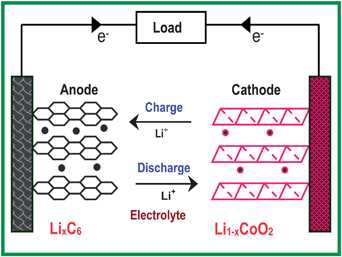 | ||
| Fig. 1 Illustration of the charge/discharge process involved in a lithium-ion cell consisting of graphite as an anode and layered LiCoO2 as a cathode. | ||
Although initial efforts were focused on transition metal chalcogenides (sulfides and selenides) as cathodes for rechargeable lithium cells,14 a recognition by Goodenough's group during the 1980's23,24 that it is difficult to stabilize higher oxidation states of transition metal ions in chalcogenides and achieve cell voltages > 2.5 V versusLi/Li+ with them led to the exploration of oxides as cathode hosts. With this perspective, several transition metal oxide hosts crystallizing in different structures have been identified as cathode materials during the past 25 years. Among them, oxides with a general formula LiMO2 (M = Mn, Co, and Ni) having a two-dimensional layered structure, LiMn2O4 having the three-dimensional spinel structure, and LiFePO4 having the olivine structure as shown in Fig. 2 have become appealing as cathodes since they exhibit a high charge/discharge potential of > 3.4 V versusLi/Li+ while graphite with a charge/discharge potential close to 0 V versusLi/Li+ and a theoretical capacity of 372 mA h g−1 has become appealing as an anode for lithium ion cells. Coupling of one of these cathodes with graphite anode offers > 3 V per cell with much higher energy densities than other rechargeable systems like lead-acid, nickel–cadmium, or metal-hydride batteries.
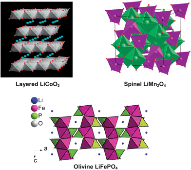 | ||
| Fig. 2 Crystal structures of various cathode materials for lithium ion batteries. | ||
However, only 50% of the theoretical capacity of LiCoO2 could be utilized in practical lithium ion cells, which corresponds to a reversible insertion/extraction of 0.5 lithium in Li1−xCoO2 and 140 mA h g−1 around 4 V versusLi/Li+. Although this limitation was attributed originally to structural transitions around (1 −x) = 0.5,25 extensive chemical delithiation experiments suggest that the limitation is related primarily to chemical instability for (1 −x) < 0.5, arising from a significant overlap of the redox active Co3+/4+:t2g band with the top of the O2−:2p band as shown in Fig. 3.26,27 On the other hand, the redox active Ni3+/4+:eg band only barely touches the top of the O2−:2p band in Li1−xNiO2, while the redox active Mn3+/4+:eg band lies well above the top of the O2−:2p band in Li1−xMnO2 as seen in Fig. 3. As a result, both the Ni3+/4+ and Mn3+/4+ couples exhibit better chemical stability than the Co3+/4+ couple in Li1−xMO2. Nevertheless, Li1−xNiO2 suffers from structural transitions and thermal runaway, while Li1−xMnO2 suffers from a layered to spinel structural transition during the charge-discharge process.28–30
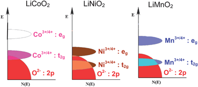 | ||
| Fig. 3 Comparison of the energy diagrams of LiCoO2, LiNiO2, and LiMnO2. | ||
The spinel LiMn2O4 with a strong edge-shared [Mn2]O4 octahedral framework, on the other hand, exhibits good structural stability during the charge-discharge process. The major issue, however, is the disproportionation of Mn3+ in presence of trace amounts of H+ ions into Mn2+ and Mn4+, resulting in a leaching out of Mn2+ ions from the cathode lattice into the electrolyte.31,32 The dissolved manganese ions subsequently deposit on the graphite anode and leads to a huge rise in impedance and severe capacity fade at elevated temperatures. Moreover, the capacity of LiMn2O4 is limited to < 120 mA h g−1 around 4 V versusLi/Li+, which corresponds to a reversible insertion/extraction of ∼ 0.8 lithium per LiMn2O4 formula unit. Although an additional lithium could be inserted into the empty octahedral sites of the [Mn2]O4 framework at a lower voltage of ∼ 3 V versusLi/Li+, it is accompanied by a macroscopic structural transition from cubic to tetragonal symmetry due to the Jahn–Teller distortion associated with the high spin Mn3+:t2g3eg1 ions, resulting in a huge volume change and severe capacity fade.24 Therefore, the capacity in the 3 V region could not be used in practical cells.
The olivine LiFePO4 with covalently bonded PO4groups and chemically more stable Fe2+/3+ couple offers excellent chemical stability.33,34 The good chemical stability is due to the lying of the Fe2+/3+:t2g band well above the top of the O2−:2p band. However, the major drawback with LiFePO4 is the poor, intrinsic electronic and lithium ion conductivities arising from a lack of mixed valency and the one-dimensional lithium ion diffusion. Although one lithium per LiFePO4 could be reversibly inserted/extracted, the presence of heavier PO4groups limits the theoretical capacity to < 170 mA h g−1 while the lower valent Fe2+/3+ couple operates at a lower voltage of ∼ 3.4 V versusLi/Li+. Also, the olivine structure is less dense than the layered and spinel structures, resulting in a lower volumetric energy density.
2.2 Nanostructured electrode materials
Although lithium-ion batteries have significantly impacted the portable electronics market, there is immense interest to increase their energy density beyond the current values pointed out in section 2.1, while satisfying other performance parameters such as high rate (power) capability and long cycle life. Design and development of breakthrough materials are needed to accomplish this objective. Nanostructured materials are appealing in this regard particularly to increase the energy density and rate capability,35 but there are advantages and disadvantages associated with them. Some of the advantages are listed below:• The short diffusion length for Li+ ion transport can enhance the rate capability and power density
• The high electrode/electrolyte contact area can help to increase the rate capability
• A better accommodation of the strain during lithium insertion/extraction can help to improve the cycle life
• The small particle size can aid to realize a better electrochemical utilization of the materials
Some of the disadvantages are given below:
• The large surface area can lead to enhanced reaction between the electrode surface and electrolyte, resulting in an increase in solid-electrolyte interfacial (SEI) layer area, self discharge, and inferior cycle life
• The low packing density of the particles can lead to lower volumetric energy density
• The complexity in the synthesis methods employed could increase the processing and manufacturing costs
With these perspectives, nanostructured materials have been pursued as both anode and cathode hosts for lithium ion batteries, and the following sections present them briefly.
However, the major issue with such nanostructured cathode materials with high surface area is the enhanced risk of secondary reactions with the electrolyte and the associated safety problems. In the case of LiMn2O4 spinel cathodes, the high surface area results in an aggravated dissolution of manganese from the spinel lattice into the electrolyte and severe capacity fade during cycling, particularly at elevated temperatures. In view of these, despite an advantage in increasing the lithium diffusion rate and rate capability, nanoparticles of layered and spinel cathodes are not particularly useful from a practical cell point of view.
Another interesting observation is that although LiMn2O4 spinel cycles poorly in the 3 V region due to the huge volume change associated with the Jahn–Teller distortion, nanostructured LiMn2O4 spinel particles formed during the charge-discharge process of the layered LiMnO2 due to the layered to spinel transition has been found to cycle well in the 3 V region.45,46 The much smaller particles of LiMn2O4 formed in situ accommodates the volume change smoothly and cycles well without encountering a breakage of inter-particle contact.
These problems are being overcome in recent years by various groups through cationic doping, decreasing the particle size via solution-based synthesis, and coating with electronically conducting agents.49–56 Keeping the particle size at the nanoscale has been particularly useful with LiFePO4 in contrast to the layered and spinel oxide cathodes discussed in section 2.2.1. While the reactivity of the highly oxidized Co3+/4+ and Ni3+/4+ couples with the electrolyte and the Mn dissolution from the spinel lattice prevent the use of nanostructured layered and spinel cathodes in practical cells, the better chemical stability of the lower valent Fe2+/3+ couple together with a lying of the Fe2+/3+:3d band well above the top of the O2−:2p band in contrast to that with the Co3+/4+:3d band in Fig. 3 avoids such problems. As a result, adoption of nanostructured samples has become particularly successful with the LiFePO4 system as the smaller particles are extremely beneficial to overcome the sluggish lithium ion diffusion rate associated with the olivine structure. We present below the microwave assisted synthesis approaches developed in our laboratory to obtain high performance nanostructured LiMPO4 (M = Mn, Fe, Co, and Ni) within a short reaction time.
2.2.2.1 Microwave assisted solvothermal and hydrothermal syntheses of nanostructured olivine cathodes. We have recently developed a novel microwave assisted solvothermal and hydrothermal approach to obtain olivine LiMPO4 (M = Mn, Fe, Co and Ni) with nanstructured morphologies and controlled particle size within a short reaction time of 5–15 min at temperatures as low as 300 °C, offering important savings in manufacturing cost.57,58 A schematic representation of the microwave-solvothermal (MW-ST) process is shown in Fig. 4. A reaction of the metal acetates with H3PO4 and LiOH in a polyol medium under solvothermal conditions offers highly crystalline, nanostructured LiMPO4. The MW-ST method56 offers a drastic reduction in synthesis time (<15 min) compared to the time consuming, traditional refluxing or heating in a furnace or in an autoclave involving 5–24 h.59,60
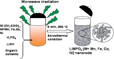 | ||
| Fig. 4 Schematic representation of the MW-ST process to produce LiMPO4 (M = Mn, Fe, Co, Ni) nanorods within 5–15 min at 300 °C. | ||
Fig. 5 shows the XRD patterns of the pristine LiMnPO4, LiFePO4, LiCoPO4, and LiNiPO4 obtained by such a MW-ST process. All the reflections could be indexed on the basis of the orthorhombic olivine structure (space group: Pnma),34 indicating the formation of phase pure samples without any impurity phases. The sharp diffraction peaks illustrate the highly crystalline nature of LiMPO4 achievable by the MW-ST process within a short time without post annealing at elevated temperatures. The reflections in Fig. 5 shift gradually to higher angles on going from M = Mn to Fe to Co to Ni due to the decrease in the ionic radii values. Energy dispersive spectroscopic (EDS) analysis in SEM and atomic absorption spectroscopic analysis of the as-synthesized LiMPO4 confirmed a Li : M : P ratio of 1 : 1 : 1.
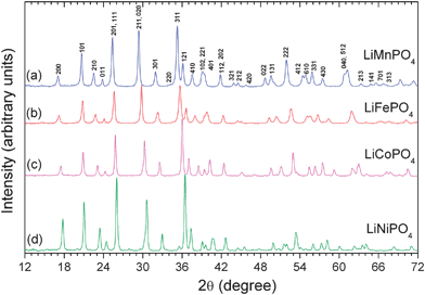 | ||
| Fig. 5 XRD patterns of the LiMPO4 (M = Mn, Fe, Co, Ni) nanorods prepared by the MW-ST method within 5–15 min at 300 °C. | ||
The TEM images shown in Fig. 6 reveal nanorod morphologies with controlled particle size. The nanorod dimension could be controlled by altering the reaction conditions such as the reactant concentrations. The high resolution TEM images with the fringes shown in Fig. 7 demonstrate the highly crystalline nature of the samples. The TEM data also reveal that each nanorod is a single crystal. Analysis of the TEM data further reveals that the nanorods grow along the [001] direction with the lithium diffusion direction (the b axis) perpendicular to the long nanorod axis as indicated in Fig. 7, which is particularly attractive to achieve fast lithium diffusion and high rate capability. Thus the MW-ST approach presented here offers a unique nanomorphology, facilitating fast lithium ion diffusion. Although one of the drawbacks with LiFePO4 is the lower discharge voltage (3.4 V versusLi/Li+), the analogous LiMnPO4, LiCoPO4, and LiNiPO4 offer much higher voltages of, respectively, 4.1, 4.8, and 5.2 V versusLi/Li+, which are beneficial to increase the energy density. However, the extremely low electronic conductivity and the Jahn–Teller distortion associated with LiMnPO4 lead to poor electrochemical performance while the lack of stable electrolytes at higher operating voltages leads to poor performance for LiCoPO4 and LiNiPO4. Development of alternate electrolytes that are stable around 5 V could make these olivine cathodes attractive for both high energy density and high power application.
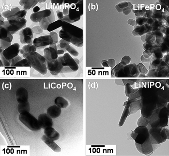 | ||
| Fig. 6 TEM images of LiMPO4 (M = Mn, Fe, Co, Ni) nanorods prepared by the MW-ST method within 5 to 15 min at 300 °C. | ||
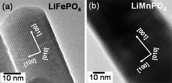 | ||
| Fig. 7 High resolution TEM images of (a) LiFePO4 and (b) LiMnPO4nanorods, showing the growth direction and the highly crystalline nature (dark fringes) of the samples. | ||
We have also developed a similar microwave assisted hydrothermal approach, employing rather the inexpensive and environmentally benign solvent, water. The microwave-hydrothermal (MW-HT) method also offers highly crystalline LiMPO4 samples at temperatures as low as 235 °C within a short reaction time (<15 min). However, the MW-HT method offers larger particle size compared to the MW-ST method, which will be discussed later.
2.2.2.2 Nano olivine/polymer nanocomposite cathodes. Although the MW-ST method offers LiMPO4nanorods with controlled particle size at temperatures as low as 300 °C, the lack of adequate electronic conductivity could still become an impediment to achieve high rate capability. Accordingly, we have encapsulated the LiFePO4nanorods obtained by the MW-ST method within a mixed electronically and ionically conducting p-toluene sulfonic acid (p-TSA) doped poly(3,4-ethylenedioxy thiophene) (PEDOT) at ambient-temperatures to obtain an organic-inorganic nanocomposite.57Fig. 8 shows the TEM images of the LiFePO4nanorods (in two different dimensions) after encapsulating within the mixed conducting polymer. The large nanorod sample in Fig. 8(a) has a width of 40 ± 6 nm and a length of up to 1 µm, while the small nanorod sample in Fig. 8(b) has a width of 25 ± 6 nm and a length of up to 100 nm. The TEM image in Fig. 8(b) reveals the transparent polymer coating (light region) on the highly crystalline LiFePO4 (dark fringes) nanorods.
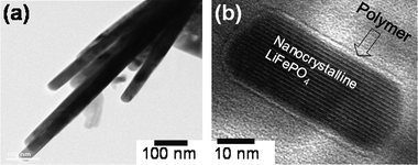 | ||
| Fig. 8 High resolution TEM image of (a) large LiFePO4nanorods (40 ± 6 nm width and up to 1 µm length) and (b) small LiFePO4nanorods (25 ± 6 nm width and up to 100 nm length) after coating with p-toluene sulfonic acid (p-TSA) doped poly(3,4-ethylenedioxythiophene) (PEDOT). | ||
Fig. 9 compares the rate capabilities of the two samples before and after coating with the conducting polymer.57 Both the samples (large and small nanorods) exhibit higher capacities after coating due to an enhancement in electronic conductivity and the synergistic effects provided by the electronically and ionically conducting doped PEDOT. Moreover, the small nanorods in Fig. 9(b) exhibit higher rate capability than the large nanorods in Fig. 9(a) due to the short lithium diffusion length in the former. We believe the nanorod morphology with the easy lithium diffusion direction (b axis) perpendicular to the long nanorod axis as indicated in Fig. 7 offers particular advantages to realize facile lithium diffusion. The small nanorods offer a capacity of 166 mA h g−1, which is close to the theoretical value of 170 mA h g−1. The data in Fig. 9 demonstrate that both the electronic and lithium ion conductivity play a critical role in controlling the electrochemical properties of olivine LiFePO4.57
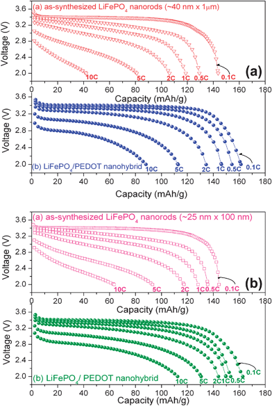 | ||
| Fig. 9 Discharge profiles of the large (40 ± 6 nm width and up to 1 µm length) and (b) small (25 ± 6 nm width and up to 100 nm length) LiFePO4nanorods after coating with p-TSA doped PEDOT. | ||
2.2.2.3 Nanoscale networking of olivine cathodes with carbon nanotubes. With an aim to enhance the electronic conductivity, we have also networked the LiFePO4nanorods synthesized by the MW-ST method with multi-walled carbon nanotubes (MWCNT) at ambient temperatures. Fig. 10 shows the SEM images of MWCNT and LiFePO4 networked with MWCNT. As seen in Fig. 11, the LiFePO4nanorods exhibit a significant improvement in rate capability after networking with MWCNT. The superior rate performance of the LiMPO4-MWCNT nanocomposite is due to the combined effect of the small lithium diffusion path length and the electronically conductive matrix provided by the carbon nanotubes.61Fig. 12 compares the cyclability of the LiFePO4-MWCNT nanocomposite with those of both the pristine sample obtained by the MW-ST method and after encapsulating within the mixed conducting polymer. The LiFePO4-MWCNT nanocomposite exhibits excellent cyclability like the LiFePO4 encapsulated within the p-TSA doped PEDOT polymer with a capacity value close to the theoretical value (170 mA h g−1).
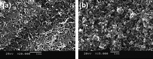 | ||
| Fig. 10 SEM images of (a) multiwalled carbon nanotubes (MWCNT) and (b) nanoscale networked LiFePO4-MWCNT nanocomposite. | ||
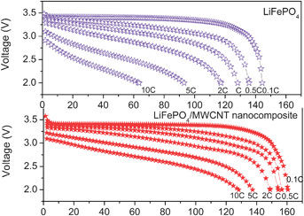 | ||
| Fig. 11 Discharge profiles at various C rates of LiFePO4nanorods before and after their nanoscale networking with MWCNT. | ||
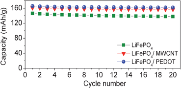 | ||
| Fig. 12 Cyclability of pristine LiFePO4 prepared by the MW-ST method, after networking it with MWCNT, and after encapsulating it with p-TSA doped PEDOT. | ||
2.2.2.4 Nano olivine/carbon nanocomposite cathodes. In another approach, we have also pursued an in situ coating of the nano LiFePO4 with conductive carbon to enhance the electronic conductivity. This was achieved by a simultaneous in situ coating of a thin nanolayer of carbon on the LiFePO4nanorodsvia a hydrothermal carbonization of glucose during the microwave hydrothermal (MW-HT) process.65 The hydrothermal carbonization of glucose not only acts as a reducing agent and offers an in situ coating of carbon on LiFePO4, but also helps to prevent the growth or agglomeration of the LiFePO4nanoparticles during the hydrothermal process.
Fig. 13(a) shows the XRD pattern of the LiFePO4/C nanocomposite obtained by the MW-HT process. The sharp diffraction peaks without any impurity phases indicate the formation of a highly crystalline, phase pure LiFePO4 at a low temperature of 235 °C within a short reaction time of 15 min by the MW-HT process. In order to improve the structural order of the carbon coating, the as-synthesized LiFePO4/C nanocomposite was further heated in an inert atmosphere at 700 °C for 1 h, and the corresponding XRD pattern is shown in Fig. 13(b). All the reflections in Fig. 13(a) and (b) could be indexed on the basis of an orthorhombic olivine-type structure with the Pnma space group, and the lattice parameter values of a = 10.321(1), b = 6.001(1), and c = 4.696(1) Å are in close agreement with the literature values.34 No reflections corresponding to carbon is seen possibly due to its low content and/or its low crystallinity.
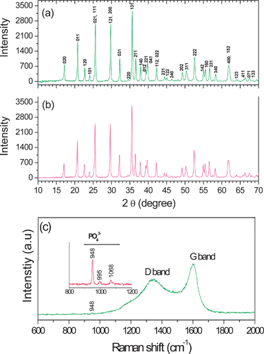 | ||
| Fig. 13 (a) XRD patterns of the as-synthesized LiFePO4/C nano-composite obtained by the facile one step microwave-hydrothermal process within ∼ 15 min, (b) XRD pattern of the LiFePO4/C nanocomposite after heating at 700 °C for 1 h in 2% H2–98% Ar, and (c) Raman spectrum of the LiFePO4/C nanocomposite. | ||
The Raman spectrum in Fig. 13(c)) shows the characteristic bands for both carbon and LiFePO4, suggesting the coating of carbon on LiFePO4. The sharp band at 948 cm−1 together with those at 995 and 1068 cm−1 can be attributed to the symmetric PO43− stretching vibration of LiFePO4 as shown in the inset of Fig. 13(c).62 The band observed at 1607 cm−1 corresponds to the graphite band (G-band), which is characteristic of carbon materials with a high degree of ordering.63 On the other hand, the band observed around 1337 cm−1 corresponds to a disorder-induced phonon mode (D-band) for disordered carbon materials. It is generally believed that the ID/IG value (the peak intensity ratio between the 1337 and 1607 cm−1 peaks) provides a useful index for comparing the degree of crystallinity of various carbon materials.64 A smaller ID/IG ratio in Fig. 13(c) indicates a high degree of ordering in the carbon coated on LiFePO4.
Fig. 14 shows the TEM images of the carbon coated LiFePO4 prepared by the MW-HT process. The images indicate well-defined, crystalline nanorod morphology with controlled size. The high resolution TEM image of the LiFePO4/C nanocomposite shown in Fig. 14(b) contrasts the LiFePO4nanorods (dark region) from the carbon coating (white region). Typically, the cabon coating was found to be 5–12 nm thick while the core LiFePO4nanorod was found to have a diameter of around 225 ± 6 nm. Also, a comparison of the TEM data before and after heat treatment at 700 °C for 1 h suggests that the high temperature treatment does not change the crystallite size of LiFePO4 as the carbon coating inhibits the crystallite growth normally encountered during high temperature heat treatment.
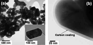 | ||
| Fig. 14 (a) TEM image of the LiFePO4/C nanocomposite obtained by the microwave-hydrothermal method after heat treatment at 700 °C for 1 h, illustrating the nanorod-like morphology and (b) high resolution TEM image of LiFePO4/C, showing the thin carbon coating on LiFePO4. | ||
Fig. 15 shows the discharge profiles collected at different C-rates and the cyclability of the as-synthesized LiFePO4/C obtained by the MW-HT method and after annealing the LiFePO4/C nanocomposite at 700 °C for 1 h.65 The annealed LiFePO4/C nanocomposite exhibits an initial discharge capacity of 150 mA h g−1 at C/10 rate, which is 88% of the theoretical capacity. Although the first initial discharge capacity values of the as-synthesized (144 mA h g−1) and annealed samples (150 mA h g−1) do not differ much, the annealed LiFePO4/C nanocomposite exhibits better rate capability compared to the as-synthesized LiFePO4/C. The cyclability data in Fig. 15(c) reveal that while the as-synthesized LiFePO4/C sample exhibits some capacity fade, the annealed sample exhibits excellent capacity retention.
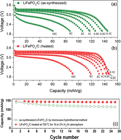 | ||
| Fig. 15 Discharge profiles recorded at different C-rates of the (a) as-synthesized LiFePO4/C nanocomposite obtained by the one step microwave-hydrothermal carbonization method, (b) after heat treating the LiFePO4/C nanocomposite at 700 °C for 1 h in 2% H2–98% Ar atmosphere, and (c) cyclability of the LiFePO4/C nanocomposite obtained by the microwave-hydrothermal method. | ||
We also carried out an ex situ coating of the LiFePO4nanorods with carbon by heating with sucrose at 700 °C for 1 h the LiFePO4nanorods obtained by the MW-ST method.65 The LiFePO4/C nanocomposite obtained by this approach exhibits higher discharge capacity of 162 mA h g−1 (Fig. 16) than that exhibited by the LiFePO4/C sample obtained by the in situ MW-HT process (150 mA h g−1) in Fig. 15 due to the smaller particle size. The LiFePO4/C nanocomposite sample also exhibits excellent cyclability with no noticeable fade compared to the as-synthesized sample obtained by the MW-ST method as seen in Fig. 16(b).
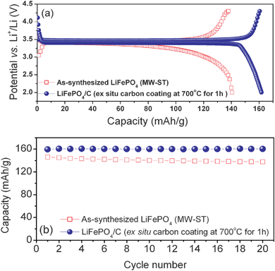 | ||
| Fig. 16 Comparison of the (a) first charge-discharge profiles recorded at C/10 rate and (b) cyclability of the as-synthesized LiFePO4nanorods obtained by the MW-ST method and the LiFePO4/C nanocomposite obtained by an ex situcarbon coating of the MW-ST LiFePO4nanorods by heating with sucrose at 700 °C for 1 h in a flowing 2% H2–98% Ar atmosphere. | ||
Fig. 17 compares the rate capacities of the LiFePO4/C nanocomposite obtained by heating the MW-ST LiFePO4 with sucrose at 700 °C and by heating at 700 °C the LiFePO4/C nanocomposite obtained by the MW-HT method. Although both samples were subjected to a constant annealing of 1 h at 700 °C, the former exhibits higher initial discharge capacity due to a smaller particle size (25 ± 6 nm and a length of up to 100 nm) compared to the latter (width of 150 ± 6 nm and a length of up to 225 nm). The observation demonstrates that both the lithium ion conduction and electronic conduction play a critical role in controlling the electrochemical properties of LiFePO4. A smaller lithium diffusion length in the MW-ST sample leads to better electrochemical properties.57,65
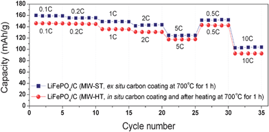 | ||
| Fig. 17 Comparison of the rate capacities of LiFePO4/C nanocomposite obtained by an ex situcarbon coating of the MW-ST LiFePO4nanorods by heating with sucrose at 700 °C for 1 h in a flowing 2% H2–98% Ar atmosphere and LiFePO4/C nanocomposite obtained by an in situcarbon coating with glucose during the MW-HT process, followed by heating at 700 °C for 1 h in a flowing 2% H2–98% Ar atmosphere. | ||
The results in sections 2.2.2.1 to 2.2.2.3 demonstrate that the microwave assisted solvothermal and hydrothermal (MW-ST and MS-HT) methods offer a facile synthesis route to obtain high performance olivine cathodes within a short reaction time, providing significant savings in manufacturing cost. Although the samples prepared by the MW-ST method exhibit higher capacity and rate capability due to the smaller particle size, the use of water as a solvent in the MW-HT process may be advantageous in terms of cost and environmental impact. Furthermore, the microwave assisted approach has the potential to access the LiMPO4 (M = Mn, Fe, Co, and Ni) olivines and their solid solutions as well as after doping with ions like Mg2+ or Zn2+ ions54 in different nanomprphologies (e.g., nanospheres, nanorods, nanosheets, and nanowires) by altering the reaction conditions.
Although nanosize particles of olivines have proved useful to overcome the poor lithium ion conduction, the small particle size could lead to less dense packing and a consequent decrease in overall volumetric energy density. The lower packing density together with the lower operating voltage of LiFePO4 make it less attractive for portable applications although it has emerged as one of the leading candidates for automobile applications.
2.2.3.1 Surface modified layered oxide cathodes. As pointed out in section 2.1, only 50% of the theoretical capacity of layered LiCoO2 cathode could be utilized in practical lithium ion cells due to the chemical instability in contact with the electrolyte for (1 −x) < 0.5 in Li1−xCoO2.26,27 One way to suppress the chemical reactivity of the cathode surface with the electrolyte is to coat or modify the surface of the cathode with other inert oxides. In fact, surface modification of the layered LiCoO2 cathode with nanostructured oxides like Al2O3, TiO2, ZrO2, SiO2, MgO, ZnO, and MPO4 ((M = Al, Fe, SrH, and Ce)) has been found to increase the reversible capacity of LiCoO2 from 140 mA h g−1 to about 200 mA h g−1, which corresponds to a reversible extraction of ∼ 0.7 lithium instead of 0.5 lithium per LiCoO2 formula unit.66–73 The surface modification suppresses the impedance growth arising from a reaction of the cathode surface with the electrolyte and improves the capacity retention to higher capacity or higher cutoff charge voltages. This demonstrates that the limitation in the practical capacity of LiCoO2 is primarily due to the chemical instability at deep charge and not due to the structural (order-disorder) transition at (1 −x) = 0.5.25 However, the long term performance of these nano-oxide cathodes will rely on the robustness of the coating. Recently, nano-coating of carbon on LiCoO2 has also been shown to improve its rate capability.74
More recently, solid solutions between layered Li[Li1/3Mn2/3]O2, which is commonly designated as Li2MnO3, and layered Li[Ni1−y−zMnyCoz]O2 have become interesting as they exhibit much higher capacities of around 250 mA h g−1.75,76 This capacity value is nearly two times higher than that found with the conventional layered LiCoO2 cathode. These layered solid solutions between Li[Li1/3Mn2/3]O2 and Li[Ni1−y−zMnyCoz]O2 exhibit an initial sloping region A, which corresponds to the oxidation of the transition metal ions to 4+ state, followed by a plateau region B, which corresponds to an oxidation of the O2− ions to neutral oxygen and an irreversible loss of oxygen from the lattice, during the first charge as seen in Fig. 18. After the first charge, the material cycles with a sloping discharge-charge profile involving a reversible reduction-oxidation of the transition metal ions. However, these layered solid solution cathodes tend to exhibit a large difference between the first charge capacity and the first discharge capacity as seen in Fig. 18, which is referred to as irreversible capacity loss.
![First charge-discharge profiles of solid solutions between layered Li[Li1/3Mn2/3]O2 and Li[Ni1−y−zMnyCoz]O2.](/image/article/2008/EE/b811802g/b811802g-f18.gif) | ||
| Fig. 18 First charge-discharge profiles of solid solutions between layered Li[Li1/3Mn2/3]O2 and Li[Ni1−y−zMnyCoz]O2. | ||
The large irreversible capacity loss is believed to be due to the extraction of lithium as “Li2O” in the plateau region B in Fig. 18 and an elimination of the oxygen vacancies formed to give an ideal composition “MO2” at the end of first charge, resulting in a less number of lithium sites available for lithium insertion/extraction during the subsequent discharge/charge cycles.77,78 However, a careful analysis of the first charge and discharge capacity values in our laboratory with a number of compositions suggests that part of the oxygen vacancies should be retained in the lattice to account for the high discharge capacity values observed in the first discharge.79 More importantly, we find that the irreversible capacity loss in the first cycle can be reduced significantly by coating these layered oxide solid solutions with nanostructured oxides and phosphates like Al2O3 and AlPO4.79,80 The TEM image shown in Fig. 19 reveals that the coating species forms a nanoporous layer of ∼ 5 nm thick on the cathode surface.
![TEM image of 4 wt.% nano AlPO4 modified Li[Li0.2Mn0.54Ni0.13Co0.13]O2 cathode.](/image/article/2008/EE/b811802g/b811802g-f19.gif) | ||
| Fig. 19 TEM image of 4 wt.% nano AlPO4 modified Li[Li0.2Mn0.54Ni0.13Co0.13]O2 cathode. | ||
Fig. 20 and 21 compare the first charge-discharge profiles and the corresponding cyclability data of a series of solid solutions between layered Li[Li1/3Mn2/3]O2 and Li[Ni1/3Mn1/3Co1/3]O2 before and after surface modification with nanostructured Al2O3.80 Clearly, the surface modified samples exhibit lower irreversible capacity loss and higher discharge capacity values than the pristine, unmodified samples. This improvement in the surface modified samples has been explained on the basis of the retention of more number of oxygen vacancies in the layered lattice after the first charge compared to that in the unmodified samples.79 It appears that the bonding of the nano-oxides to the surface of the layered oxide lattice suppresses the diffusion of the oxygen vacancies and their elimination.
![First charge-discharge profiles of the layered (1 −x)Li[Li1/3Mn2/3]O2–xLi[Ni1/3Mn1/3Co1/3]O2 solid solutions before and after surface modification with 3 wt.% nanostructured Al2O3, followed by heating at 400 °C.](/image/article/2008/EE/b811802g/b811802g-f20.gif) | ||
| Fig. 20 First charge-discharge profiles of the layered (1 −x)Li[Li1/3Mn2/3]O2–xLi[Ni1/3Mn1/3Co1/3]O2 solid solutions before and after surface modification with 3 wt.% nanostructured Al2O3, followed by heating at 400 °C. | ||
![Cyclability of the layered (1 −x)Li[Li1/3Mn2/3]O2–xLi[Ni1/3Mn1/3Co1/3]O2 solid solutions before and after surface modification with 3 wt.% nanostructured Al2O3, followed by heating at 400 °C.](/image/article/2008/EE/b811802g/b811802g-f21.gif) | ||
| Fig. 21 Cyclability of the layered (1 −x)Li[Li1/3Mn2/3]O2–xLi[Ni1/3Mn1/3Co1/3]O2 solid solutions before and after surface modification with 3 wt.% nanostructured Al2O3, followed by heating at 400 °C. | ||
It is remarkable that the surface modified (1−x)Li[Li1/3Mn2/3]O2–xLi[Ni1/3Mn1/3Co1/3]O2 composition with x = 0.4 exhibits a high discharge capacity of ∼ 280 mA h g−1, which is two times higher than that of LiCoO2. However, one drawback with these oxides is that they require charging up to about 4.8 V and more stable, compatible electrolyte compositions need to be developed to fully exploit their potential as high energy density cathodes. Moreover, oxygen is lost irreversibly from the lattice during the first charge, and it may have to be vented appropriately during cell manufacturing. Also, the long-term cyclability of these high capacity cathodes needs to be fully assessed.
2.2.3.2 Surface modified spinel oxide cathodes. As pointed out in section 2.1, the major issue with the LiMn2O4 spinel cathode is the Mn dissolution from the lattice in contact with the electrolyte. Accordingly, coating of the LiMn2O4 spinel cathode with nanostructured oxides like Al2O3, TiO2, ZrO2, SiO2, MgO, and ZnO has been found to suppress the Mn dissolution from the spinel lattice in contact with the electrolyte and improve the capacity retention.81–84 However, the coated species could strip off during long term cycling, and the challenge is to achieve robust coatings that will be stable under aggressive charge–discharge conditions.
Another drawback with the spinel LiMn2O4 cathode is the lower energy density arising from a limited capacity of < 120 mA h g−1 compared to the layered oxide cathodes. In this regard, the LiMn1.5Ni0.5O4 spinel cathode is appealing as it offers a discharge capacity of around 130 mA h g−1 at a higher voltage of 4.7 V versusLi/Li+. However, the spinel LiMn1.5Ni0.5O4 encounters the formation of NiO impurity during synthesis and the phase with an ordering between Mn4+ and Ni2+ has been found to exhibit inferior performance than the disordered phase.85 We have found that the formation of the NiO impurity phase and the ordering could be suppressed by appropriate cation doping as in LiMn1.5Ni0.42Zn0.08O4 and LiMn1.42Ni0.42Co0.16O4.86
One major concern with the spinel LiMn1.5Ni0.5O4 cathode is the chemical stability in contact with the electrolyte at the higher discharge voltage of 4.7 V versusLi/Li+. To overcome this difficulty, we have modified the surface of the cation substituted LiMn1.42Ni0.42Co0.16O4 cathode with nanostructured oxides like Al2O3.87 The surface modified cathodes exhibit better cyclability and rate capability retention as the material is cycled compared to the unmodified pristine sample. A careful investigation of the cathodes by electrochemical impedance spectroscopy before and after surface modification with the nanostructured Al2O3 reveals that the improvement is due to a decrease in both the solid-electrolyte interfacial (SEI) layer resistance and electron transfer resistance. It appears that the surface modification suppresses the reaction between the cathode surface and the electrolyte and modifies the SEI layer formation. The results suggest that surface modification is an effective way to improve the chemical stability of the 4.7 V spinel cathodes in contact with the electrolyte and improve their cyclability and rate capability during long term cycling.
Alloying of lithium with other elements like Si, Sn, and Ge are appealing as anodes since some of them exhibit high theoretical capacities of >1000 mA h g−1.90–92 However, the major challenge with these alloys is the huge volume change occurring during the discharge-charge process, which leads to a breaking of inter-particle contact and severe capacity fade during cycling. One approach that is being pursued to overcome this problem is to embed the electrochemically active nano-size clusters in an electrochemically active or inactive matrix to suppress the strain considerably and improve the reversibility of the lithium insertion/extraction reaction.93–97 Examples of this include formation of nanocomposites of silicon with carbon, graphite and SiOx.95–97 Another approach that is being pursued is one-dimensional nanowires that can accommodate large strain with good electrical contact without pulverization during the charge-discharge process.90,91 The nanowire strategy with both Si and Ge has been found to improve the cyclability significantly with high capacities, but it could lead to significant reduction in overall volumetric energy density.
Metal oxides that undergo displacement reactions have also been found to exhibit high capacities. For example, SnO2 reacts with lithium to form Li2O and nanosize tin particles.98–101 The Sn particles are finely dispersed in the Li2O matrix, and the Li2O surrounding the tin particles accommodates the mechanical stresses occurring during the alloy formation-decomposition process. This greatly improves the cycling performance although there is a significant irreversible capacity loss during the first cycle and agglomeration of tin particles tend to occur during prolonged cycling. More recently, a variety of nano-architectures have also been pursued as anode hosts.102,103 Employing novel synthesis approaches, for example, mesoporous SnO2 grown on multi-walled carbon nanotubes, carbon nanotube coated SnO2nanowire arrays,104 hollow core-shell mesospheres of SnO2 and carbon, and tin particles encapsulated in hollow carbon spheres have been found to exhibit interesting electrochemical properties. Additionally, nanostructured oxides like FeO, NiO and CoO involving a displacement reaction with lithium to form Li2O and Fe, Ni, or Co have also been found to show reversibility. However, they exhibit higher voltages versusLi/Li+ compared to carbon anodes, resulting in a lower cell voltage.105
In addition, nanocrystalline Li4Ti5O12 crystallizing in the spinel structure exhibits excellent lithium insertion/extraction properties with little volume change (near zero strain material) during charge-discharge cycling. Interestingly, it does not form any undesirable solid-electrolyte interfacial (SEI) layer or any serious safety problems unlike the carbon anode.106 Also, it is not poisoned by the dissolved manganese released by the LiMn2O4 cathode. A lying of the Ti3+/4+:t2g band well above the top of the O2−:2p band and the excellent chemical stability of the Ti3+/4+ couple (due to a smaller work function compared to the Co3+/4+ couple) allow the nanostructured Li4Ti5O12 work well like LiFePO4 without encountering any undesirable reaction with the electrolyte. However, the main drawback with Li4Ti5O12 is that it exhibits a much lower capacity of 175 mA h g−1 at a much higher voltage of 1.5 V versusLi/Li+, resulting in a significant reduction in the energy density of the lithium ion cells. Recently, nanocoating of carbon on Li4Ti5O12 has also been pursued to improve its rate performance.107
Overall, nanomaterials and nanoarchitectures offer great potential to overcome some of the persistent problems with the anodes. Although, the small particle size could decrease the volumetric energy density as in the case of nano olivines, the significantly much higher capacities of the alloy anode materials can readily offset this issue. Novel synthesis and processing approaches could greatly benefit the development of successful alloy anodes.
3. Electrochemical energy conversion
3.1 Fuel cells as energy conversion systems
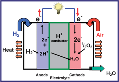
Fuel cells are an attractive option for energy conversion as they offer high efficiency with little or no pollution. Among the various types of fuel cells, the proton exchange membrane fuel cells (PEMFCs) and direct methanol fuel cells (DMFC) are appealing for automotive and portable electronic applications due to their low temperature (< 100 °C) of operation. The science and technology of fuel cells are available extensively in reviews and dedicated books,108–113 and the readers may refer to them for more details. Fig. 22 illustrates the operating principles of a PEMFC that uses hydrogen as a fuel and oxygen as an oxidant. While the H+ ions produced by an electrocatalytic oxidation of H2 gas by the Pt catalyst migrates from the anode to the cathode through the proton-conducting Nafion membrane, the electrons flow through the external circuit from the anode to the cathode, where it electrocatalytically reduces with the assistance of the Pt catalyst the O2 gas to O2− ions, which combines with the H+ ions to produce water. The free energy change involved in the chemical reaction (2) below is tapped out as electricity:| 2 H2 + O2→ 2 H2O | (2) |
However, the commercialization of the fuel cell technology is hampered by high cost, durability, and operability problems, which are linked to severe materials challenges. For example, the limited abundance and high cost of Pt catalyst,114,115 its instability (dissolution, precipitation, and migration) during cell operation,116–118 and poisoning by the methanol fuel that may crossover from the anode to the cathode through the Nafion membranes are some of the serious problems to be addressed.108 For transportation applications, the cost of a PEMFC system is estimated to be $200–300 kW−1, and the cost of platinum contributes to half of it.114 Design and development of breakthrough electrocatalysts that can overcome these difficulties are critical to advance the technology. Nanomaterials and nanotechnology play a critical role in this regard, and the sections below provide an overview of some of the recent developments in nanostructured electrocatalysts.
3.2 Nanostructured electrocatalysts
The oxygen reduction reaction (ORR) involving a four electron transfer is much more sluggish than the hydrogen oxidation reaction (HOR) in a PEMFC. This requires a much higher catalyst loading for ORR at the cathode than for HOR at the anode, implying a significantly higher contribution of the cathode to the cost of PEMFC. Nanostructured Pt with a particle size of about 3 nm is still the state-of-the-art electrocatalyst for ORR in PEMFC and DMFC. A great deal of research effort has been devoted both to identify less expensive electrocatalysts and to lower the Pt loading in the membrane-electrode assembly (MEA). For example, alloying of Pt with other less expensive metals like Cr, Fe, Co, Ni and Cu,119–124 as well as development of alternative electrocatalysts such as metal carbides,125 metal oxides,126 metal chalcogenides,127,128 enzymes,129,130 and platinum-free metal combinations131–136 have been widely pursed over the years for ORR. Also, extensive efforts have been made to lower the amount of the expensive Pt catalyst per unit area.137–142 In these efforts, innovative synthesis approaches and optimization of the particle size as well as novel processing and fabrication methodologies play a critical role in achieving high catalytic activity. The sections below focus on some of the recent developments in our laboratory on platinum-based and platinum-free nanoalloy electrocatalysts for ORR.We have developed a novel synthesis approach based on microwave solvothermal (MW-ST) method to obtain nanostructured alloy catalysts with a high degree of alloying at lower temperatures (300 °C).146Fig. 23(a) compares the XRD patterns of the Pt70Pd20Co10 and Pt75Co25 samples synthesized by the MW-ST method at 300 °C without any post annealing in reducing atmospheres. The (111) reflections shift to higher angles compared to that of Pt, indicating the substitution of smaller Co and Pd for Pt. The decrease in unit cell volume from 60.38 Å3 for Pt to 54.08 and 58.45 Å3, respectively, for Pt75Co25 and Pt70Pd20Co10 and a correlation between the degree of alloying and lattice parameter values indicate that most of the Co and Pd are incorporated into the Pt lattice.
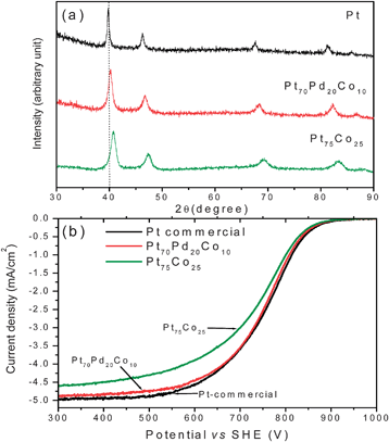 | ||
| Fig. 23 (a) XRD patterns of Pt, Pt75Co25, and Pt70Pd20Co10. The dotted line refers to the expected position of the (111) reflection of Pt. (b) Comparison of the hydrodynamic polarization curves of Pt75Co25 and Pt70Pd20Co10 with that of commercial Pt (Alpha Aesar HiSpec 3000) that were recorded in O2 saturated 0.5M H2SO4 with a rotation speed of 1600 rpm at room temperature (the current density refers to geometric area). The sweep rate was 5 mV s−1. | ||
Fig. 23(b) compares the hydrodynamic polarization curves obtained in O2 saturated 0.5 M H2SO4 at 1600 rpm. The ternary Pt70Pd20Co10 catalyst exhibits catalytic activity for ORR similar to that of commercial Pt catalyst despite a larger particle size (7.7 nm) compared to that of Pt (2–3 nm). It is interesting to note that Pt70Pd20Co10 exhibits slightly higher catalytic activity than Pt75Co25 although they have comparable particle sizes (7.7 nm for Pt70Pd20Co10 and 6.2 nm for Pt75Co25). The cost of Pd is 20% of the cost of Pt, and the substitution of both Pd and Co for Pt decreases the catalyst cost significantly. The results suggest that microwave assisted solvothermal approach offers a potential route to obtain high degree of alloying at low temperatures and achieve high catalytic activity.146
ORR is a multi-electron process, involving a number of reaction steps, intermediates, and adsorbed species. The rate determining step and the kinetics not only differ for different electrocatalysts, but also dependent on the crystal faces of the electrocatalysts. For example, Pt(111) has been found to be more active than Pt(100) in perchloric acid. The lower activity of Pt(100) has been explained on the basis of a strong adsorption of OH− ions that inhibit ORR by decreasing the number of available active sites.147 Enhanced ORR activity of the Pt-alloy catalysts has been explained by (i) modification of the electronic structure of Pt (5d-orbital vacancies), (ii) changes in the Pt-Pt bond distance and coordination number, and (iii) inhibition of adsorbed oxygen-containing species from the electrolyte onto the Pt surface.143,148–151 More recently, it has been suggested that the electrocatalytic activity is dependent on the interaction between oxygen 2p states and the metal d states. The filling of the antibonding states of O2:2p, which determines the strength of interaction of the metal-oxygen bond, is dependent on the position of the metal d states relative to the Fermi level.152–157 A shifting of the metal d states upward relative to the Fermi level results in less filling of antibonding states and a strong metal-oxygen bond. It has also been found that Pt enriched surfaces in bi-metallic alloys enhance ORR by inhibiting OH− adsorption.155,156
Fig. 24 compares the XRD patterns of the carbon supported Pd100−xMox (0 ≤x≤ 40) and Pd100−xWx (0 ≤x≤ 30) catalysts that were synthesized by a thermal decomposition of palladium acetylacetonate and molybdenum carbonyl or tungsten carbonyl solutions in o-xylene, followed by heat treatment at 700–900 °C in H2 atmosphere for 2 h.165 The reflections in Fig. 24 are characteristic of a face-centered cubic lattice. Due to similar atomic sizes, the formation of a solid solution alloy between Pd and Mo or W could not be established from the XRD data alone. However, the Pd–Mo and Pd–W phase diagrams suggests that the formation of a face centered cubic solid solution up to 33 atom% Mo and 23 atom% W and phase separations on increasing the Mo or W contents further.166 In the case of Pd–Mo system, no impurity phases are seen at 700 °C but reflections corresponding to the Mo2C impurity phase are seen after heat treating Pd60Mo40 at 900 °C. However, no Mo2C phase is seen in the case of Pd70Mo30 even after heat treating at 900 °C, suggesting the formation of single phase solid solution up to about 30 atom % Mo after annealing at 900 °C, which is consistent with the literature phase diagram data.166 Similarly, in the Pd–W system, reflections corresponding to metallic W appear in Pd70W30 after heat treatment at 800 °C, indicating the formation of solid solution at least up to 20 atom% W, which is consistent with the literature phase diagram data.166 Both X-ray photoelectron spectroscopic (XPS) analysis and energy dispersive spectroscopic (EDS) analysis in SEM confirmed the homogeneity of the samples with no surface segregation, which is consistent with the theoretical calculations of Ruben et al.167
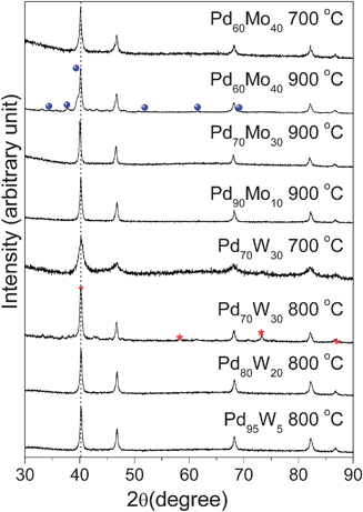 | ||
| Fig. 24 XRD patterns of Pd-Mo and Pd-W samples after heat treatment at 700–900 °C in H2 atmosphere. The dotted line refers to the expected position of the (111) reflection of Pd. The reflections marked with ● in Pd60Mo40 refer to the Mo2C impurity phase and ★ in Pd70W30 correspond to the W impurity phase. | ||
Fig. 25 compares the TEM photographs of Pd and Pd90Mo10 before and after heat treatment at 900 °C. The data indicate a good dispersion of the catalysts on the carbon support with a mean particle diameter of 5.6 nm for the as-synthesized Pd90Mo10 and 4.5 nm for the as-synthesized Pd. However, the particle size increases significantly on annealing at 900 °C, and the 900 °C Pd90Mo10 sample has larger particle size than the 900 °C Pd sample.
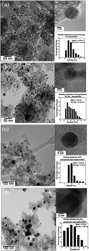 | ||
| Fig. 25 TEM images and particle size distributions of (a) as-synthesized Pd, (b) as-synthesized Pd90Mo10, (c) 900 °C Pd, and (d) 900 °C Pd90Mo10. | ||
Fig. 26(a) compares the catalytic activity for ORR of selected Pd–Mo and Pd–W electrocatalysts after heat treatment at, respectively, 900 and 800 °C with that of as-synthesized Pt electrocatalyst. As seen, the catalytic activity of the Pd–Mo and Pd–W alloy catalysts are close to that of as-synthesized Pt although the particle sizes of the Pd–Mo and Pd–W electrocatalysts are almost two times larger than that of the as-synthesized Pt. Further increase in W or Mo beyond 5 or 10 atom% was found to decrease the catalytic activity, indicating an optimum Mo or W content to maximize the catalytic activity. Furthermore, cyclic voltammetry experiments in 0.5 M H2SO4 revealed that the alloying of Pd with Mo or W suppresses the dissolution of Pd and increases the durability.165
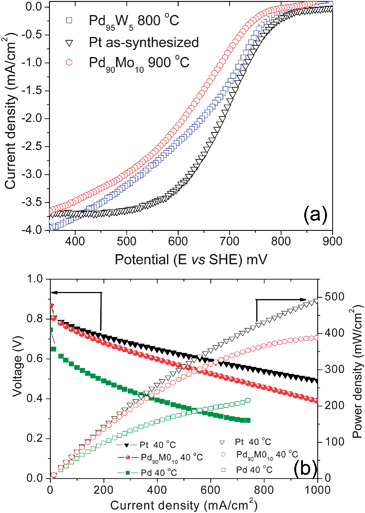 | ||
| Fig. 26 (a) Comparison of the hydrodynamic polarization curves (ORR) of Pd90Mo10 and Pd95W5 after heat treatment at, respectively, 900 and 800 °C with that of as-synthesized Pt under conditions similar to that described in Fig. 23(b). Comparison of the catalytic activity for ORR in single cell PEMFC at 40 °C of as-synthesized Pt, 900 °C Pd90Mo10, and 900 °C Pd with a catalyst loading of 0.4 mg cm−2 at both the anode and cathode. | ||
Fig. 26(b) compares the performance in single cell PEMFC of 900 °C heat treated Pd and Pd90Mo10 with that of as-synthesized Pt at 40 °C. The data demonstrate that alloying of Pd with Mo increases the catalytic activity significantly for ORR. Similar results were also found with the Pd95W5 electrocatalyst. Moreover, the activity of Pd90Mo10 is close to that of as-synthesized Pt. However, the data in Fig. 26(b) were collected at 40 °C, and it was found that as the temperature increases, the difference between the activities of Pt and Pd90Mo10 become more pronounced since the catalytic activity of Pt increases much more rapidly with increasing temperature compared to that of Pd90Mo10. Nevertheless, the Pd-based alloy catalysts exhibit remarkable tolerance to methanol, suggesting its significant advantage in DMFC to lower the catalyst loading and improve the performance. Although limited literature is available, it has been suggested that the Pd-based alloy electrocatalysts promote a four-electron pathway for the oxygen reduction reaction.164,167,168 As in the case of Pt and Pt-based alloys like Pt–Co, Pt–Ni, and Pt–Fe, the kinetics of the net oxygen reduction reaction will depend on two competing processes: the dissociative adsorption of O2 and the subsequent transfer of electrons and protons to the adsorbed O2 and the removal of adsorbed OH and O species from the surface.152,155,156 Theoretical calculations suggest that oxygen binds more strongly with Pd than with Pt.
As pointed out earlier, one of the major concerns with the platinum electrocatalyst is its dissolution, migration and subsequent precipitation,114,115 resulting in a loss of electrochemical active surface area and catalytic activity during long term operation. The dissolution problem is even more severe in the case of palladium.161,163 However, we have demonstrated that alloying of Pd with other elements like Mo and W reduces dissolution significantly. Moreover, further studies are required to establish the long term stability of the Pd-based alloy electrocatalysts. Another issue is that our present synthesis procedure for Pd-based alloy electrocatalysts like Pd-Mo and Pd-W results in larger particle size with a wider size distribution due to the higher heat treatment temperature (800 °C) to realize alloy formation. It is imperative that alternative synthesis approaches for Pd-based alloys to obtain smaller particle size (2–3 nm) and narrow size distribution need to be developed. While platinum and its alloys have been studied extensively for ORR, relatively less information is available in the literature for palladium and its alloys. The reaction pathway and the intermediates generated during ORR on palladium and its alloys are yet to be established. Further studies could help to design and develop non-platinum electrocatalysts with improved performance and stability.
Conclusions
This review presented an overview of how nanostructured materials can impact the electrochemical energy storage and conversion technologies like lithium ion batteries and fuel cells. Recent developments towards new materials or on known materials with improved properties, employing novel synthesis and processing approaches, have been discussed.While the reduced particle size in nanostructured materials can enhance the lithium diffusion rate in lithium ion battery electrode materials, the high reactivity of the highly oxidized redox couples such as Co3+/4+ and Ni3+/4+ with the electrolyte prevents the use of nanosize particles of cathodes like layered LiCoO2 and spinel LiMn2O4 in practical cells. In contrast, the better chemical stability of the lower valent Fe2+/3+ couple along with the covalently bonded PO4groups avoids such reactivity problems with the olivine LiFePO4 cathodes. In fact, the reduction in particle size to the nanometer scale has become extremely critical to overcome the poor one-dimensional lithium ion diffusion rate in LiFePO4. Novel low temperature synthesis approaches such as the microwave assisted solvothermal and hydrothermal (MW-ST and MW-HT) methods described in this article prove particularly useful to obtain nanostructured LiMPO4 (M = Mn, Fe, Co, and Ni) cathodes with controlled particle size, while significantly reducing the reaction time and temperature and offering cost savings in manufacturing. Such approaches also offer great potential to obtain the olivine cathodes in different nanomorphologies by tuning the reaction medium and conditions. Subsequent networking with conductive carbon or mixed ionic-electronic conducting polymers overcome the difficulties of the poor electronic and lithium ion conduction in the olivine cathodes and help to achieve superior electrochemical properties needed for high power applications like HEV and PHEV. Similarly, the nanosize particles work extremely well with the spinel Li4Ti5O12 anodes without encountering any reactivity problems with the electrolyte due to the lower potential (∼ 1.5 V) versusLi/Li+ and excellent chemical stability of the Ti3+/4+ couple. Nanomaterials and novel nano-architectures also offer great potential to develop next generation anodes with high energy densities.
Novel synthesis approaches such as the microwave-solvothermal method also offer great potential to obtain nanostructured electrocatalysts with high degree of alloying while keeping the particle size small and maximizing the electrochemical active area. The high degree of alloying that could be achieved at lower temperatures could help to enhance the durability and robustness of the alloy electrocatalysts while achieving high electrocatalytic activity. The novel synthetic approaches could also become powerful to develop multi-metallic alloy electrocatalysts containing three or more metals with a high degree of alloying and homogeneity that may be difficult to realize with other conventional synthesis approaches.
Overall, nanomaterials and nanotechnology combined with novel synthesis approaches offer great potential to develop new materials that can lower the cost, improve the performance, and enhance the commercial viability of electrochemical energy storage and conversion technologies. Although this article focused mainly on lithium ion battery electrode materials and fuel cell electrocatalysts, such methodologies could also help other electrochemical energy technologies like supercapacitors. Successful development of low cost, more efficient materials will powerfully impact the increasing global demand for energy and our environment, while building a firm scientific base on the structure-composition-property-performance relationships of nanostructured materials.
Acknowledgements
Financial support by the Office of Vehicle Technologies of the U.S. Department of Energy under Contract No. DE-AC02-05CH11231, National Science Foundation grant CBET- 0651929, MURI grant N00014-07-1-0758, and the Welch Foundation grant F-1254 is gratefully acknowledged.References
- Y. Sun and Y. Xia, Science, 2002, 298, 2176 CrossRef CAS.
- D. R. Rolison, Science, 2003, 299, 1698 CrossRef CAS.
- X. Duan, C. Niu, V. Sahi, J. Chen, J. W. Parce, S. Empedocles and J. L. Goldman, Nature, 2003, 425, 274 CrossRef CAS.
- Y. Xia, P. Yang, Y. Sun, Y. Wu, B. Mayers, B. Gates, Y. Yin, F. Kim and H. Yan, Adv. Mater., 2003, 15, 353 CrossRef CAS.
- P. G. Bruce, B. Scrosati and J. M. Tarascon, Angew. Chem., Int. Ed., 2008, 47, 2930 CrossRef CAS.
- N. Tian, Z.-Y. Zhou, S.-G. Sun, Y. Ding and Z. L. Wang, Science, 2007, 316, 732 CrossRef CAS.
- A. T. Appapillai, A. N. Mansour, J. Cho and Y. Shao-Horn, Chem. Mater., 2007, 19, 5748 CrossRef CAS.
- J. W. Long, R. M. Stroud, K. E. Swider-Lyons and D. R. Rolison, J. Phys. Chem. B, 2000, 104, 9772 CrossRef CAS.
- D. R. Rolison and B. Dunn, J. Mater. Chem., 2001, 11, 963 RSC.
- Handbook of batteries, ed. D. Linden, McGraw Hill, New York, 2nd edn, 1995 Search PubMed.
- Lithium batteries, ed. J. P. Gabano, Academic Press, London, 1995 Search PubMed.
- Lithium battery technology, ed. H. V. Venkatasetty, John Wiley, New York, 1984 Search PubMed.
- Lithium batteries: new materials, developments and perspectives, ed. G. Pistoia, Elsevier, Amsterdam, 1994, vol. 5 Search PubMed.
- Solid state batteries: materials design and optimization, ed. C. Julien and G. A. Nazri, Kluwer, Boston, 1994 Search PubMed.
- Lithium ion batteries: fundamentals and performance, ed. M. Wakihara and O. Yamamoto, Wiley-VCH, Weinheim, 1998 Search PubMed.
- Materials for Electrochemical Energy Conversion and Storage, Ceramic Transactions, ed. A. Manthiram, P. N. Kumta, S. K. Sundaram and G. Ceder, American Ceramic Society, Westerville, OH, 2002, vol. 127 Search PubMed.
- Advances in Lithium-Ion Batteries, ed. W. Van Schalkwijk and B. Scrosati, Kluwer Academic/Plenum, New York, 2002 Search PubMed.
- Science and technology of lithium batteries, ed. G. A. Nazri and G. Pistoia, Kluwer Academic Publishers, Boston, MA, 2003 Search PubMed.
- J. W. Long, B. Dunn, D. R. Rolison and H. S. White, Chem. Rev., 2004, 104, 4463 CrossRef CAS.
- M. Winter and R. J. Brodd, Chem. Rev., 2004, 104, 4245 CrossRef CAS.
- M. M. Thackeray, S.-H. Kang, C. S. Johnson, J. T. Vaughey, R. Benedek and S. A. Hackney, J. Mater. Chem., 2007, 17, 3112 RSC.
- Y. Wang and G. Cao, Adv. Mater., 2008, 20, 2251 CrossRef CAS.
- K. Mizushima, P. C. Jones, P. J. Wiseman and J. B. Goodenough, Mater. Res. Bull., 1980, 15, 783 CrossRef CAS.
- M. M. Thackeray, W. I. F. David, P. G. Bruce and J. B. Goodenough, Mater. Res. Bull., 1983, 18, 461 CrossRef CAS.
- J. N. Reimers and J. R. Dahn, J. Electrochem. Soc., 1992, 139, 2091.
- S. Venkatraman, Y. Shin and A. Manthiram, Electrochem. Solid-State Lett., 2003, 6, A9 CrossRef CAS.
- J. Choi, E. Alvarez, T. A. Arunkumar and A. Manthiram, Electrochem. Solid-State Lett., 2006, 9, A241 CrossRef CAS.
- R. Armstrong and P. G. Bruce, Nature, 1996, 381, 499 CrossRef CAS.
- F. Capitaine, P. Gravereau and C. Delmas, Solid State Ionics, 1996, 89, 197 CrossRef CAS.
- S. Choi and A. Manthiram, J. Electrochem. Soc., 2002, 149, A1157 CrossRef CAS.
- D. H. Jang, Y. J. Shin and S. M. Oh, J. Electrochem. Soc., 1996, 143, 2204 CAS.
- H. Yamane, T. Inoue, M. Fujita and M. Sano, J. Power Sources, 2001, 99, 60 CrossRef CAS.
- A. K. Padhi, K. S. Nanjundaswamy, C. Masquelier, S. Okada and J. B. Goodenough, J. Electrochem. Soc., 1997, 144–5, 1609 CrossRef.
- A. K. Padhi, K. S. Nanjundasawamy and J. B. Goodenough, J. Electrochem. Soc., 1997, 144, 1188 CAS.
- A. S. Arico, P. Bruce, B. Scrosati, J.-M. Tarascon and W. V. Schalkwijk, Nat. Mater., 2005, 4, 366 CrossRef CAS.
- A. Vadivel Murugan, B. B. Kale, L. B. Kunde and A. V. Kulkarni, J. Solid State Electrochem., 2006, 10, 104 CrossRef CAS.
- N. Treuil, C. Labrugere, M. Menetrier, J. Portier, G. Campet, A. Deshayes, J.-C. Frison, S.-J. Hwang, S.-W. Song and J.-H. Choy, J. Phys. Chem. B, 1999, 103, 2100 CrossRef CAS.
- D. Im and A. Manthiram, J. Electrochem. Soc., 2002, 149, A1001 CrossRef CAS.
- C. H. Lu and H. C. Wang, J. Mater. Chem., 2003, 13, 428 RSC.
- Z. Liu, A.-L. Wang, X. Liu, M. Wu, D. Li and Z. Zeng, J. Solid State Chem., 2004, 177, 1585 CrossRef CAS.
- Y.-S. Hong, Y. J. Park, K. S. Ryu, S. H. Chang and M. G. Kim, J. Mater. Chem., 2004, 14, 1424 RSC.
- A. Caballero, M. Cruz, L. Hernan, M. Melero, J. Morales and E. R. Castellón, J. Power Sources, 2005, 150, 192 CrossRef CAS.
- Y. Lee, M. G. Kim and J. Cho, Nano Lett., 2008, 8, 957 CrossRef CAS.
- C. H. Jiang, S. X. Dou, H. K. Liu, M. Ichihara and H. S. Zhou, J. Power Sources, 2007, 172, 410 CrossRef CAS.
- Y. Shao-Horn, S. A. Hackney, A. R. Armstrong, P. G. Bruce, R. Gitzendanner, C. S. Johnson and M. M. Thackeray, J. Electrochem. Soc., 1999, 146, 2404 CrossRef CAS.
- H. Wang, Y. I. Jang and Y. M. Chiang, Electrochem. Solid-State Lett., 1999, 2, 490 CrossRef CAS.
- A. Manthiram and J. B. Goodenough, J. Solid State Chem., 1987, 71, 349 CrossRef CAS.
- A. Manthiram and J. B. Goodenough, J. Power Sources, 1989, 26, 403A.
- S.-Y. Chung, J. T. Bloking and Y.-M. Chiang, Nat. Mater., 2002, 1, 123 CrossRef CAS.
- Y. Wang, J. Wang, J. Yang and Y. Nuli, Adv. Funct. Mater., 2006, 16, 2135 CrossRef CAS.
- R. Dominko, M. Gaberscek, J. Drofenik, M. Bele, S. Pejovnik and J. Jamnik, J. Power Sources, 2003, 119–121, 770 CrossRef CAS.
- B. Ellis, W. H. Ka, W. R. M. Makahnou and L. F. Nazar, J. Mater. Chem., 2007, 17, 3248 RSC.
- J. D. Wilcox, M. M. Doeff, M. Marcinek and R. Kostecki, J. Electrochem. Soc., 2007, 154, A389 CrossRef CAS.
- C. S. Wang and J. Hong, Electrochem. Solid-State Lett., 2007, 10, A65 CrossRef CAS.
- M. M. Doeff, Y. Hu, F. McLarnon and R. Kostecki, Electrochem. Solid-State Lett., 2003, 6, A207 CrossRef.
- H. Liu, Q. Cao, L. J. Fu, C. Li, Y. P. Wu and H. Q. Wu, Electrochem. Commun., 2006, 8, 1553 CrossRef CAS.
- A. Vadivel Murugan, T. Muraliganth and A. Manthiram, Electrochem. Commun., 2008, 10, 903 CrossRef CAS.
- A. Vadivel Murugan, T. Muraliganth and A. Manthiram, Inorg. Chem., submitted Search PubMed.
- S. Franger, F. Le Cras, C. Bourbon and H. Rouanlt, J. Power Sources, 2003, 119–121, 252 CrossRef CAS.
- J. Lee and A. S. Teja, Mater. Lett., 2006, 60, 2105 CrossRef CAS.
- T. Muraliganth, A. Vadivel Murugan and A. Manthiram, J. Mater. Chem. 10.1039/b812165f.
- M. S. Bhuvaneswari, N. N. Bramnik, D. Ensling, H. Ehrenberg and W. Jaegermann, J. Power Sources, 2008, 180, 553 CrossRef CAS.
- Q. Wang, H. Li, L. Chen and X. Huang, Carbon, 2001, 39, 2211 CrossRef CAS.
- M. S. Dresselhaus, G. Dresselhaus, A. Jorio, A. G. Souza Filho and R. Saito, Carbon, 2002, 40, 2043 CrossRef CAS.
- A. Vadivel Murugan, T. Muraliganth and A. Manthiram, J. Phys. Chem. C, 2008, 112, 14665 CrossRef.
- J. Kim, M. Noh, J. Cho, H. Kim and K. Kim, J. Electrochem. Soc., 2005, 152, A1142 CrossRef CAS.
- B. Kim, C. Kim, T. Kim, D. Ahn and B. Park, J. Electrochem. Soc., 2006, 153, A1773 CrossRef CAS.
- Y. J. Kim, J. Cho, T.-J. Kim and B. Park, J. Electrochem. Soc., 2003, 150, A1723 CrossRef CAS.
- L. Lui, Z. Wang, H. Li, L. Chen and X. Huang, Solid State Ionics, 2002, 152–153, 341 CrossRef CAS.
- J. Cho, C.-S. Kim and S.-I. Yoo, Electrochem. Solid-State Lett., 2000, 3, 362 CAS.
- A. M. Kannan, L. Rabenberg and A. Manthiram, Electrochem. Solid-State Lett., 2003, 6, A16 CrossRef CAS.
- Z. Wang, X. Huang and L. Chen, J. Electrochem. Soc., 2003, 150, A199 CrossRef CAS.
- T. Fang, J. Duh and S. Sheen, J. Electrochem. Soc., 2005, 152, A1701 CrossRef CAS.
- Q. Cao, H. P. Zhang, G. J. Wang, Q. Xia, Y. P. Wu and H. Q. Wu, Electrochem. Commun., 2007, 9, 1228 CrossRef CAS.
- Z. Lu, L. Y. Beaulieu, R. A. Donaberger, C. L. Thomas and J. R. Dahn, J. Electrochem. Soc., 2002, 149, A778 CrossRef CAS.
- T. A. Arunkumar, Y. Wu and A. Manthiram, Chem. Mater., 2007, 19, 3067 CrossRef CAS.
- R. Armstrong, M. Holzapfel, P. Novak, C. S. Johnson, S.-H. Kang, M. M. Thackeray and P. G. Bruce, J. Am. Chem. Soc., 2006, 128, 8694 CrossRef CAS.
- M. M. Thackeray, S.-H. Kang, C. S. Johnson, J. T. Vaughey, R. Benedek and S. A. Hackney, J. Mater. Chem., 2007, 17, 3112 RSC.
- Y. Wu, A. Vadivel Murugan and A. Manthiram, J. Electrochem. Soc., 2008, 155, A635 CrossRef CAS.
- Y. Wu and A. Manthiram, Electrochem. Solid-State Lett., 2006, 9, A221 CrossRef CAS.
- Y. Sun, K. Hong and J. Prakash, J. Electrochem. Soc., 2003, 150, A970 CrossRef CAS.
- J. Han, S. Myung and Y. Sun, J. Electrochem. Soc., 2006, 153, A1290 CrossRef CAS.
- A. M. Kannan and A. Manthiram, Electrochem. Solid-State Lett., 2002, 5, A167 CrossRef CAS.
- M. M. Thackeray, C. S. Johnson, J. S. Kim, K. C. Lauzze, J. T. Vaughey, N. Dietz, D. Abraham, S. A. Hackney, W. Zeltner and M. A. Anderson, Electrochem. Commun., 2003, 5, 752 CrossRef CAS.
- J.-H. Kim, S.-T. Myung, C. S. Yoon, I.-H. Oh and Y.-K. Suna, J. Electrochem. Soc., 2004, 151, A1911 CrossRef CAS.
- T. A. Arun Kumar and A. Manthiram, Electrochem. Solid-State Lett., 2005, 8, A403 CrossRef CAS.
- J. Liu and A. Manthiram, J. Electrochem. Soc., submitted Search PubMed.
- M. Winter, J. O. Besenhard, M. E. Spahr and P. Novák, Adv. Mater., 1998, 10, 725 CrossRef CAS.
- S. Megahed and B. Scrosati, J. Power Sources, 1994, 51, 79 CrossRef CAS.
- C. K. Chan, H. Peng, G. Liu, K. McIlwrath, X. F. Zhang and Y. Cui, Nat. Nanotechnol., 2008, 3, 31 Search PubMed.
- C. K. Chan, X. F. Zhang and Y. Cui, Nano Lett., 2008, 8, 307 CrossRef CAS.
- D. W. Kim, I. S. Hwang, S. J. Kwon, H. Y. Kang, K. S. Park, Y. J. Choi, K. J. Choi and J. G. Park, Nano Lett., 2007, 7, 3041 CrossRef CAS.
- J. M. Tarascon and M. Armand, Nature, 2001, 414, 359 CrossRef CAS.
- J. Hassoun, P. Reale and B. Scrosati, J. Mater. Chem., 2007, 17, 3668 RSC.
- T. Zhang, L. Fu, J. Gao, L. Yang, Y. Wu and H. Wu, Pure Appl. Chem., 2006, 78(10), 1889 CrossRef CAS.
- T. Zhang, J. Gao, L. Fu, L. C. Yang, Y. P. Wu and H. Q. Wu, J. Mater. Chem., 2007, 17, 1321 RSC.
- T. Zhang, J. Gao, H. P. Zhang, L. C. Yang, Y. P. Wu and H. Q. Wu, ElectroChem. Commun., 2007, 9, 886 CrossRef CAS.
- Y. Idota, T. Kubota, A. Matsufuji, Y. Maekawa and T. Miyasaka, Science, 1997, 276, 1395 CrossRef CAS.
- I. A. Courtney and J. R. Dahn, J. Electrochem. Soc., 1997, 144, 2045 CAS.
- T. Brousse, R. Retoux, U. Herterich and D. M. Schleich, J. Electrochem. Soc., 1998, 145, 1 CAS.
- M. R. MacKinnon and J. R. Dahn, J. Electrochem. Soc., 1999, 146, 59 CrossRef CAS.
- Z. Wen, Q. Wang, Q. Zhang and J. Li, Adv. Funct. Mater., 2007, 17, 2772 CrossRef CAS.
- W. M. Zhang, J. S. Hu, Y. G. Guo, S. F. Zheng and L. S. Zhong, Adv. Mater., 2008, 20, 1160 CrossRef CAS.
- N. Zhao, G. Wang, Y. Huang, B. Wang, B. Yao and Y. Wu, Chem. Mater., 2008, 20, 2612 CrossRef CAS.
- P. Poizot, S. Laruelle, S. Grugeon, L. Dupont and J. M. Tarascon, Nature, 2000, 407, 496 CrossRef CAS.
- E. Ferg, R. J. Gummow, A. de Kock and M. M. Thackeray, J. Electrochem. Soc., 1994, 141, L147 CAS.
- G. J. Wang, J. Gao, J. l. Fu, N. H. Zhao, Y. P. Wu and T. Takamura, J. Power Sources, 2007, 174, 1109 CrossRef CAS.
- Handbook of Fuel Cells–Fundamentals, Technology and Applications, ed. W. Vielstich, H. A. Gasteigner and A. Lamm, John Wiley & Sons, Ltd., 2003, vol. 2 Search PubMed.
- A. J. Appleby and F. R. Foulkes, Fuel Cell Handbook, Van Nostrand Reinhold, New York, 1989 Search PubMed.
- J. C. Larminie and A. Dicks, Fuel Cell Systems Explained, John Wiley and Sons Ltd, New York, 2nd edn, 2003 Search PubMed.
- K. B. Prater, J. Power Sources, 1994, 51, 129 CrossRef CAS.
- B. C. H. Steele and A. Heinzel, Nature, 2001, 414, 345 CrossRef CAS.
- G. J. K. Acres, J. Power Sources, 2001, 100, 60 CrossRef CAS.
- I. Bar-On, R. Kirchain and R. Roth, J. Power Sources, 2002, 109, 71 CrossRef CAS.
- R. J. Spiegel, Transport. Res., Part D: Transport and Environment, 2004, 9, 357 Search PubMed.
- P. J. Ferreira, G. J. la O', Y. Shao-Horn, D. Morgan, R. Makharia, S. Kocha and H. A. Gasteiger, J. Electrochem. Soc., 2005, 152, A2256 CrossRef.
- P. J. Ferreira and Y. Shao-Horn, Electrochem. Solid-State Lett., 2007, 10, B60 CrossRef CAS.
- Y. Shao-Horn, W. C. Sheng, S. Chen, P. J. Ferreira, E. F. Holby and D. Morgan, Top. Catal., 2007, 46, 285 CrossRef CAS.
- M. T. Paffett, J. G. Beery and S. Gottesfeld, J. Electrochem. Soc., 1988, 135, 1431 CrossRef CAS.
- M. Watanabe, K. Tsurumi, T. Mizukami, T. Nakamura and P. Stonehart, J. Electrochem. Soc., 1994, 141, 2659 CAS.
- M. Neergat, A. K. Shukla and K. S. Gandhi, J. Appl. Electrochem., 2001, 31, 373 CrossRef CAS.
- L. Xiong, A. M. Kannan and A. Manthiram, Electrochem. Commun., 2002, 4, 898 CrossRef CAS.
- L. Xiong and A. Manthiram, J. Mater. Chem., 2004, 14, 1454 RSC.
- L. Xiong and A. Manthiram, Electrochim. Acta, 2005, 50, 2323 CrossRef CAS.
- J. G. Chen, Chem. Rev., 1996, 96, 1477 CrossRef CAS.
- J. M. Zen and C. B. Wang, J. Electrochem. Soc., 1994, 141, L51 CrossRef CAS.
- V. Trapp, P. Christensen and A. Hamnett, J. Chem. Soc., Faraday Trans., 1996, 92, 4311 RSC.
- N. A. Vante and H. Tributsch, Nature, 1986, 323, 431 CAS.
- N. Mano, J. L. Fernandez, Y. Kim, W. Shin, A. J. Bard and A. Heller, J. Am. Chem. Soc., 2003, 125, 15290 CrossRef CAS.
- N. Mano, H. H. Kim, Y. Zhang and A. Heller, J. Am. Chem. Soc., 2002, 124, 6480 CrossRef CAS.
- S. Ye and A. K. Vijh, Electrochem. Commun., 2003, 5, 272 CrossRef CAS.
- R. Pattabhiraman, Appl. Catal., A, 1997, 153, 9 CrossRef CAS.
- O. Savadago, K. Lee, K. Oishi, S. Mitsushima, N. Kamiya and K. I. Ota, Electrochem. Commun., 2004, 6, 105 CrossRef CAS.
- J. L. Fernández, V. Raghuveer, A. Manthiram and A. J. Bard, J. Am. Chem. Soc., 2005, 127, 13100 CrossRef CAS.
- V. Raghuveer, A. Manthiram and A. J. Bard, J. Phys. Chem. B, 2005, 109, 22909 CrossRef CAS.
- V. Raghuveer, P. J. Ferreira and A. Manthiram, Electrochem. Commun., 2005, 8, 807.
- S. H. Joo, S. J. Choi, I. Oh, J. Kwak, Z. Liu, O. Terasaki and R. Ryoo, Nature, 2001, 412, 169 CrossRef CAS.
- V. Raghuveer and A. Manthiram, Electrochem. Solid-State Lett., 2004, 7, A336 CrossRef CAS.
- M. C. R. Martinez, D. C. Amoros, A. L. Salano, C. S. Martinez, H. Yamashita and M. Anpo, Carbon, 1995, 33, 3 CrossRef CAS.
- S. Mukerjee, S. Srinivasan, M. Soriaga and J. McBreen, J. Electrochem. Soc., 1995, 142, 1409 CAS.
- T. Toda, H. Igarashi, H. Uchida and M. Watanabe, J. Electrochem. Soc., 1999, 146, 3750 CrossRef CAS.
- T. Tada, H. Igarashi and M. Watanabe, J. Electroanal. Chem., 1999, 460, 258 CrossRef CAS.
- K. Kinoshita, Electrochemical Oxygen Technology, John Wiley and Sons Ltd, New York, 1992 Search PubMed.
- L. Xiong and T. He, Electrochem. Commun., 2006, 8, 1671 CrossRef CAS.
- H. Liu and A. Manthiram, Electrochem. Commun., 2008, 10, 740 CrossRef CAS.
- A. Vadivel Murugan, A. Sarkar and A. Manthiram, to be sumitted.
- N. Markovic, H. Gasteiger and P. N. Ross, J. Electrochem. Soc., 1997, 144, 1591 CAS.
- R. Adzicin, Recent Advances in the Kinetics of Oxygen Reduction in Electrocatalysis, ed. J. Lipkowski and P. N. Ross, Wiley-VCH, New York, 1998, pp. 197 Search PubMed.
- D. B. Sepa, M. V. Vojnovic and A. Damjanovic, Electrochim. Acta, 1980, 25, 1491 CrossRef CAS.
- S. Mukerjee, S. Srinivasan, M. P. Soriaga and J. McBreen, J. Phys. Chem., 1995, 99, 4577 CrossRef CAS.
- V. Jalan and E. J. Taylor, J. Electrochem. Soc., 1983, 130, 2299 CAS.
- V. Stamenkovic, B. S. Mun, K. J. Mayrhofer, P. N. Ross, N. M. Markovic, J. Rossmeisl, J. Greeley and J. K. Nørskov, Angew. Chem., Int. Ed., 2006, 45, 2897 CrossRef CAS.
- J. Greeley, J. K. Norskov and M. Mavrikakis, Annu. Rev. Phys. Chem., 2002, 53, 319 CrossRef CAS.
- N. M. Markovi, T. J. Schmidt, V. Stamenkovic and P. N. Ross, Fuel Cells, 2001, 1, 105 CrossRef CAS.
- V. Stamenkovic, B. S. Mun, K. J. Mayrhofer, P. N. Ross and N. M. Markovic, J. Am. Chem. Soc., 2006, 128, 8813 CrossRef CAS.
- V. Stamenkovic, B. Fowler, B. S. Mun, G. Wang, P. N. Ross, C. A. Lucas and N. M. Markovic, Science, 2007, 315, 493 CrossRef CAS.
- J. Zhang, F. Lima, M. Shao, K. Sasaki, J. Wang, J. Hanson and R. Adzic, J. Phys. Chem. B, 2005, 109, 22701 CrossRef CAS.
- W. Wang, D. Zheng, C. Du, Z. Zou, X. Zhang, B. Xia, H. Yang and D. L. Akins, J. Power Sources, 2007, 167, 243 CrossRef CAS.
- J. R. Kitchin, J. K. Norskov, M. A. Barteau and J. G. Chen, J. Chem. Phys., 2004, 120, 10240 CrossRef CAS.
- A. Eichler, F. Mittendorfer and J. Hafner, Phys. Rev. B, 2000, 62, 4744 CrossRef CAS.
- K. Juodkazis, J. Juodkazyt, B. Sebeka, G. Stalnionis and A. Lukinskas, Russ. J. Electrochem., 2003, 39, 954 CrossRef CAS.
- L. D. Burke and J. K. Casey, J. Electrochem. Soc., 1993, 140, 1284 CAS.
- S. H. Cadle, J. Electrochem. Soc., 1974, 121, 645 CAS.
- W. E. Mustain, K. K. Keith and J. Prakash, Electrochem. Commun., 2006, 8, 406 CrossRef CAS.
- A. Sarkar, A. Vadivel Murugan and A. Manthiram, J. Phys. Chem. C, 2008, 112, 12037 CrossRef CAS.
- ASM Metals Handbook, ASM International, 2007, vol. 3 Search PubMed.
- A. V. Ruban, H. L. Skriver and J. K. Norskov, Phys. Rev. B: Condens. Matter Mater. Phys., 1999, 59, 15990 CrossRef.
- L. Zhang, L. Kunchan and J. Zhang, Electrochim. Acta, 2007, 52, 3088 CrossRef CAS.
| This journal is © The Royal Society of Chemistry 2008 |

