Recent developments in proton exchange membranes for fuel cells
Ram
Devanathan
*
Chemical and Materials Sciences Division, Pacific Northwest National Laboratory, MS K8-87, Richland, WA 99352, USA. E-mail: ram.devanathan@pnl.gov; Fax: +1-509-371-6242; Tel: +1-509-371-6487
First published on 27th June 2008
Abstract
Proton exchange membranes (PEMs) that operate at temperatures above 120 °C are needed to avoid catalyst poisoning, enhance electrochemical reactions, simplify the design and reduce the cost of fuel cells. This review summarizes developments in PEMs over the last five years. In order to design new membranes for elevated temperature operation, one must understand the chemistry, morphology and dynamics of protons and water molecules in existing membranes. The integration of experiment with modelling and simulation can shed light on the hierarchical structure of the membrane and dynamical processes associated with molecular transport. Based on such a fundamental understanding, membranes can be modified by controlling the polymer chemistry and architecture or adding inorganic fillers that can retain water under low relative humidity conditions. The development of anhydrous membranes based on phosphoric acid doped polymers, ionic liquid-infused polymer gels and solid acids can enable fuel cell operation above 150 °C. Considerable work remains to be done to identify proton transport mechanisms in novel membranes and evaluate membrane durability under real world operating conditions.
 Ram Devanathan Ram Devanathan | Ram Devanathan received his BTech in Metallurgical Engineering from the Indian Institute of Technology Madras and his PhD in Materials Science and Engineering from Northwestern University. He is currently a Senior Scientist in the Chemical & Materials Sciences Division at Pacific Northwest National Laboratory. His research interests include polymer electrolyte membranes and solid oxide fuel cells, hydrogen storage, nuclear reactor materials and nuclear waste disposal. |
1. Introduction
The rising global energy demand and the environmental impact of energy use from traditional sources pose serious challenges to human health, energy security, environmental protection and the sustainability of natural resources. It is widely understood that increased energy use presents the easiest route to achieving prosperity and enhancing quality of life for large segments of the human population.1 Over the last century, this goal has been accomplished by burning fossil fuels with adverse environmental consequences. The continued growth in global population, steadily increasing per-capita energy consumption in developing countries, and dependence on fossil fuel resources located in politically volatile regions make the fossil fuel-based economy unsustainable. Recently, a hydrogen-based economy has been proposed2 as an alternative to the current fossil-fuel economy, but it is far from being widely realized. Considerable progress in the fundamental science of sustainable hydrogen production, storage and efficient use in fuel cells is needed to realize the vision of a hydrogen economy.Proton exchange membrane (also known as polymer electrolyte membrane) fuel cells (PEMFCs) represent a critical step in the proposed hydrogen economy. PEMFCs convert chemical energy of the fuel (hydrogen, methanol or formic acid) into electrical energy with high efficiency (∼60%) and minimal environmental pollution. Since PEMFCs are modular and have a simple design, they can be scaled up in size to suit the demands of a variety of applications. They have the potential to revolutionize transportation, which consumes 60% of the worldwide production of petroleum,3 improve stationary power generation thereby reducing dependence on the electrical grid and provide reliable portable power for our ever-increasing array of personal electronic devices. Fuel cell technology has been used to power automobiles, scooters, buses, backup power generators, boats, underwater vehicles, locomotives and laptop computers.4 Widespread commercialization of PEMFC technology has been stymied by high cost and the need for significant advances in hydrogen production and storage, and the performance, durability and service life of fuel cells under operating conditions.
The heart of the PEMFC is a polymer electrolyte membrane (PEM) that separates the reactant gases and conducts protons as shown in Fig. 1. The hydrogen fuel (on the anode side) and oxygen from air (on the cathode side) flow separately through grooves in the bipolar plate, then through a porous gas diffusion layer and in to a catalyst layer loaded with precious metal catalysts on carbon support. At the anode catalyst layer, hydrogen dissociates into protons that are transported through the membrane and electrons that flow through an external circuit. At the cathode catalyst layer, oxygen combines with the protons and electrons to form water and heat as by-products. The desired membrane properties for PEMFC include excellent proton conductivity and poor electron conductivity, low permeability for reactant gases, minimal crossover of water and fuel especially for direct methanol and formic acid fuel cells (DMFCs and DFAFCs), compatibility with electrode materials, dimensional stability during fuel cell operation (minimal swelling and shrinking), good mechanical strength, chemical and thermal stability, durability under prolonged operation (∼5000 h for transportation applications5) at elevated temperatures and during freeze–thaw cycles, and low cost. None of the available membranes meets all of these requirements.
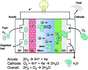 | ||
| Fig. 1 Schematic diagram of a PEM fuel cell. BP, GD, CL and Mem represent bipolar plates, gas diffusion layers, catalyst layers and membrane, respectively. | ||
A 2005 cost analysis6 of an 80 kW PEMFC system for transportation, assuming high volume production of 500![[thin space (1/6-em)]](https://www.rsc.org/images/entities/char_2009.gif) 000 units, projected a cost of $108 kW−1, which is below the United States Department of Energy's (DOE) 2005 target of $125 kW−1 but considerably higher than the 2015 DOE target of $30 kW−1. The cost of the stack was projected to be $68 kW−1 and the rest ($40 kW−1) arises from assembly and balance-of-plant components for water, heat and fuel management. The membrane–electrode assembly (MEA) accounts for 83% of the cost of the stack ($56 kW−1). The pressing need to overcome MEA cost and membrane degradation issues has driven an exponentially growing interest in this field as shown in Fig. 2 by the number of journal articles found in the scientific database Scopus.7 The article search was performed using all of the following keywords: polymer, electrolyte, membrane, fuel and cell.
000 units, projected a cost of $108 kW−1, which is below the United States Department of Energy's (DOE) 2005 target of $125 kW−1 but considerably higher than the 2015 DOE target of $30 kW−1. The cost of the stack was projected to be $68 kW−1 and the rest ($40 kW−1) arises from assembly and balance-of-plant components for water, heat and fuel management. The membrane–electrode assembly (MEA) accounts for 83% of the cost of the stack ($56 kW−1). The pressing need to overcome MEA cost and membrane degradation issues has driven an exponentially growing interest in this field as shown in Fig. 2 by the number of journal articles found in the scientific database Scopus.7 The article search was performed using all of the following keywords: polymer, electrolyte, membrane, fuel and cell.
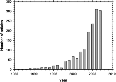 | ||
| Fig. 2 Number of journal articles on polymer electrolyte membrane fuel cell based on a search using Scopus.7 | ||
The most widely used PEM, Nafion®, was developed 40 years ago by DuPont Inc.8 In Nafion, a hydrophobic perfluorinated polyethylene backbone and a highly hydrophilic sulfonic acid-terminated perfluoro vinyl ether pendant are known to form nanoscale domains within which ionic transport occurs.9,10 The chemical structure of Nafion is shown in Fig. 3. Typical values of x and y are 7 and 1, respectively. Nafion has endured as the prototypical membrane for PEMFCs, because it offers high proton conductivity11 (0.13 S cm−1 at 75 °C and 100% relative humidity [RH]), chemical stability, and longevity (> 60000 h) in a fuel cell environment.12 However, it has several deficiencies that have stimulated a vigorous search for better membrane materials. Nafion is expensive, allows methanol crossover easily in DMFCs with adverse effect on performance, cannot function well at high temperatures (above 80 °C) or low humidity (below ∼80% RH), and requires external humidification and therefore management of water.12
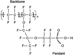 | ||
| Fig. 3 Chemical structure of Nafion. | ||
Proton dissociation from the SO3H groups and subsequent proton transport in Nafion depends on the presence of liquid water, because water molecules facilitate proton transfer and serve as shuttles for proton transport.13 The need for liquid water in the membrane constrains the operating temperature below 100 °C in principle and 80 °C in practice. Moreover, protons traversing the hydrated membrane drag water molecules along from the anode to the cathode (electro-osmotic drag) as illustrated in Fig. 1. There is also a flux of water molecules (back-diffusion) from the cathode to the anode driven by the water concentration gradient. Imbalance between these two fluxes can cause severe performance degradation due to drying of the anode catalyst layer and flooding of the cathode catalyst layer, mechanical stresses in the membrane, delamination of the catalyst layer, and pinhole formation in the membrane leading to gas crossover, catalyst sintering and failure.12,14 The need to externally manage water distribution in the membrane adds to the system volume, weight, complexity and cost.
Operation of PEMFCs above 120 °C is desirable for a number of reasons. Elevated temperature operation enhances the kinetics of electrode reactions and improves CO tolerance. At 80 °C, CO adsorbs on the Pt catalyst and diminishes the fuel cell performance. To avoid this CO poisoning, the CO content has to be maintained as low as 20 ppm in the fuel stream at 80 °C.15 CO tolerance increases to 1000 ppm at 130 °C and 30000 ppm at 200 °C due to CO desorption.15 At temperatures above 120 °C, flooding of the catalyst layers can be avoided due to the elimination of liquid water, the cooling system will be simplified as a result of a larger temperature difference with the ambient, waste heat may be recovered, and it may be feasible to use non-precious metal catalysts.16 In view of these considerations, DOE has set the following 2010 targets for PEM: conductivity: 0.1 S cm−1 during operation at 120 °C and 1.5 kPa inlet water vapour partial pressure; unassisted start from −40 °C; O2 and H2 crossover: 2 mA cm−2; elevated temperature durability: 2000 h with cycling; and cost: $20 m−2.17
In order to realize the potential of fuel cells, there is a need for rational design of novel membrane materials based on a fundamental understanding of membrane chemistry, proton transfer, nanophase segregation, membrane morphology, proton and molecular transport, and mechanical properties. Current membrane research is focused on developing membranes that retain water at elevated temperatures or that provide good conductivity in the absence of water. Several articles have reviewed various aspects of membrane development for PEMFCs.9,12,15,16,18–30 The strategies being explored include modifying the pendant groups of existing membranes, incorporating hygroscopic oxides and heteropoly acids in the membrane to retain water, using aromatic backbone polymers, and replacing water with a less volatile proton solvent.22 The aim of this review is to highlight developments over the past five years in membranes for PEMFCs. The references cited here are not meant to be comprehensive but serve as starting points for further exploration of this fascinating subject. The review is organized as follows: section 2 reports on the current experimental and theoretical understanding of Nafion membranes; section 3 discusses other perfluorinated membranes; section 4 presents recent developments in aromatic backbone membranes; section 5 discusses anhydrous membranes; section 6 presents the summary and outlook for membrane development.
2. Recent progress in understanding Nafion membrane
Extensive efforts to synthesize a high-temperature PEMFC membrane have failed to yield a candidate that outperforms Nafion. An important first step in rational design of novel PEMs is to obtain a molecular-level understanding of chemistry, morphology, transport and degradation in existing membranes, such as Nafion, under various operating conditions. Nafion is known to have a nanoscale phase-separated structure with hydrophobic regions that provide mechanical support and hydrophilic domains that facilitate proton transport.9 The distribution of the two phases from the nanoscale to the microscale has been the subject of much debate. The morphology is known to change with hydration level, processing conditions (melt extruded vs. solution cast) and thermal history. It is important to obtain a fundamental understanding of Nafion morphology in order to optimize transport and mechanical properties of the membrane.2.1 Recent experimental studies of Nafion
The structure, proton and small molecule transport processes and mechanical properties of Nafion have been studied extensively by experiment. Neutron and X-ray scattering,9,19,31–40 nuclear magnetic resonance (NMR),41–44 infrared (IR) spectroscopy,45–49 electron and atomic force microscopy,31,50,51 differential scanning calorimetry,52 dielectric relaxation spectroscopy,53,54 alternating current (ac) impedance spectroscopy,35,39,40,51 dynamic mechanical analysis11 and electron spin resonance spectroscopy55 are among the many techniques that have been used to characterize membrane materials.Several simple models of Nafion morphology have been constructed to fit the experimental small angle X-ray and neutron scattering (SAXS and SANS) data. The SAXS intensity curve of hydrated Nafion shows a characteristic ionomer peak at about q = 1.1 nm − 1, where q is the scattering vector. At smaller q values, the intensity varies as q−1, while at larger values there is a steep q−4 variation.56,57 One of the earliest models of Nafion, the cluster-network model,56 proposes spherical ionic clusters with an inverse micelle structure. Hydrated Nafion is modelled as a periodic arrangement of ionic clusters of 3–5 nm diameter interconnected by narrow water channels of 1 nm width. The cluster size and the water content were considered to change with changing hydration level. Presently, the cluster-network model is considered too simplistic because of the assumption of periodic distribution of spherical clusters. This assumption is at odds with the q−1 variation of the SAXS intensity at small q, which is typical of elongated structures.57
Litt58 proposed a simple lamellar model of Nafion with water absorbing between hydrophilic micelles separated by hydrophobic lamellae. A related model is the rectangular parallelepiped sandwich model32 with a core region sandwiched between shells made of hydrophilic groups and polymer side-chains. The lateral dimensions are 1.5–4.5 nm and the total thickness of the sandwich is about 6 nm. The core region is empty in the dry membrane and filled with water in hydrated Nafion. The anisotropic distribution of this basic structural unit gives rise to water channels. The model mainly presents information about the basic structural unit without dealing explicitly with the mesoscale structure.
Gebel et al.33,34 have analyzed SANS and ultra SAXS to probe Nafion structure in the length scale from 1 nm to 1 μm. Their structural model is based on elongated (cylindrical or ribbon-like) polymer aggregates with a diameter of about 4 nm and length larger than 100 nm. These aggregates are surrounded by ionic groups and packed in bundles with ordered orientation. The ionomer peak in SAXS represents the average distance between the aggregates in a typical bundle. The bundles are randomly arranged at the mesoscale. Kim et al.59 have recently proposed a model based on SANS results in which ionic clusters can form a network with cylindrical water channels.
Schmidt-Rohr and Chen57 have shown that none of the models discussed above can match the experimental SAXS data satisfactorily. They have performed a quantitative analysis of published SAXS curves and proposed a new model of hydrated Nafion. Their model consists of parallel cylindrical water channels that have diameters between 1.8 and 3.5 nm and persistence length of more than 20 nm as shown in Fig. 4(a). The cylindrical inverted micelles are lined with hydrophilic groups and are stabilized by the stiff polymer backbone. In Fig. 4(b) packing of parallel cylinders of varying diameter is shown. The cylinder diameter is much larger than that in other models, such as the cluster-network model,56 which explains the large water diffusion coefficient (within an order of magnitude of that in bulk water), methanol permeation and electro-osmotic drag of water in Nafion. Unlike previous simulations of SAXS curves that ignored crystallinity, this model incorporates 10 vol% of crystallites that run parallel to the water channels. The crystallites and water channels are shown in red and white, respectively in the cross-section in Fig. 4(c). The SAXS intensity I(q), shown in Fig. 4(d), calculated from this model reproduces the ionomer peak at q ≈ 1.1 nm−1 and also the q−1 dependence at lower q and q−4 dependence at higher q observed by Rubatat et al.33 Schmidt-Rohr and Chen57 have concluded that polymers with more flexible backbones and stiffer side-chains, such as aromatic polymer membranes, would have smaller diameter channels resulting in lower water diffusion coefficients and less methanol permeation. However, the finer details of polymer self-association are not evident from this model60 and it is not clear if this model can represent Nafion at low hydration levels.
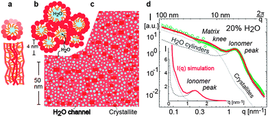 | ||
| Fig. 4 Illustration of the parallel water channel model of Nafion.57 (a) Cross-sectional and transverse views of an inverted micelle cylinder. Darker shades represent features closer to the viewer; (b) packing of inverted micelle cylinders; (c) cross-section of the simulated system showing water channels (white), Nafion crystallites (red) and amorphous Nafion matrix (orange); (d) SAXS intensity I(q) as a function of scattering vector q. The experimental data of Rubatat et al.33 are in green and the model curve is in red (solid line). The simulated curves from the water channels only (dashed) and crystallites only (dotted) are also shown. Inset shows the same plot over a longer range of q. Reprinted from ref. 57 by permission from Macmillan Publishers Ltd, Nature Materials, copyright 2008. | ||
In addition to these morphological studies, the distribution and interactions of water molecules in Nafion have been examined by infra-red (IR) spectroscopy.45–49 According to Laporta et al.,46 small water clusters form in Nafion 117 for hydration levels of λ < 3, aggregate into larger clusters for λ = 3 to 5 and start coalescing into a water network for λ > 6. The notation 117 refers to the equivalent weight (EW) of 1100 g mol−1 of SO3− groups and a membrane thickness of 0.007 inch (∼178 μm), and λ is the number of water molecules per SO3− group. The strength of hydrogen-bonding and the number of hydrogen-bonds increase with λ.46 Moilanen et al.48,49 used IR spectroscopy to study water in Nafion 117 over a range of λ from 1 to 9. Their findings indicate that an abrupt structural change occurs in the membrane around λ = 5, which drastically reduces the number of bound water molecules. Moilanen et al.48 state that some H2O molecules may be in close proximity to the fluorocarbon backbone. However, Basnayake et al.47 have studied water permeation into poly(hexafluoropropylene-co-tetrafluoroethylene) (FEP) membrane and found no evidence of water incorporation near the fluorocarbon. Lu et al.54 have observed an abrupt change in the dielectric constant of hydrated Nafion 117 at λ = 9 and have attributed it to the onset of percolation of hydrophilic domains.
Quasi-elastic neutron scattering (QENS) has also been used to examine the dynamics of water molecules in PFSA membranes. Pivovar and Pivovar35 examined water dynamics in Nafion 117 using QENS at 295 K for λ varying from 1 (nearly dry) to 16 (well hydrated). The authors fitted their data using a simple model based on continuous diffusion within a sphere. Their data shows two distinct regimes of hydration: (1) for λ ≤ 7, the fraction of non-diffusing (fND) hydrogen atoms decreases rapidly with increasing λ (from 0.85 at λ =1 to 0.20 at λ = 6); (2) for λ > 7, fND shows asymptotic behaviour and reaches a value of 0.12 at λ = 16. All the extracted parameters were found to change rapidly in the low λ range and to tend toward asymptotic values in the high λ range. This is consistent with the observation that the increase of water uptake by Nafion with increasing relative humidity41,46 has a gradual slope for λ < 6 and a steep slope for higher λ, which indicates that water molecules are more likely to be bound to sulfonate groups at low λ. Surprisingly, the diffusion coefficients of water molecules obtained by Pivovar and Pivovar35 are comparable to that in bulk water and considerably larger than those determined by Zawodzinski et al.41 using NMR. In contrast to the above result of Pivovar and Pivovar (fND = 0.2 for λ = 6),35 a QENS study of water dynamics in hydrated Nafion 115 (∼127 μm thick) by Paciaroni et al.37 found fND to be about 0.5 for λ ∼6 at 295 K. This difference has been attributed37 to better energy resolution in the former measurement, which enables tracking the motion of protons over a longer time window.
A recent QENS study by Perrin et al.39 has examined molecular motion in Nafion 112 (∼51 μm thick) at 298 K for λ ranging from 3 to 17.5. The authors used a single theoretical model based on Gaussian statistics valid over the whole entire range of q studied to interpret their data, instead of a simple diffusion in a sphere model.61 At all hydration levels examined, two distinct populations of protons were observed. Both have characteristic length scales of 0.2–0.4 nm, but the characteristic time scales differ by a factor of about 50 at all hydration levels (2–8 ps vs. 160–500 ps). The authors39 have identified the slow proton dynamics with hydronium ion (H3O+) dynamics and estimated the H3O+ lifetime in Nafion to be of the order of 1 ns in contrast to the H3O+ lifetime of 10 − 4 ns in bulk water.62 The fast proton dynamics have been associated with local diffusion of water molecules. It has been proposed that the proton exists as H3O+ ion at low λ and as H3O+ ion surrounded by H2O molecules in the fully hydrated membrane. The difference in the time scale of the two populations is explained by the stronger binding of the H3O+ to the SO3− group. The conclusion of Perrin et al.39 that proton transport in Nafion occurs by the vehicular mechanism only involving a well defined H3O+ ion at all hydration levels is at odds with the conclusion of Zawodzinski et al.41 based on NMR and conductivity measurements that proton transport by the Grotthuss mechanism13,25,63 becomes increasingly significant for λ > 5. In fact, proton transport in Nafion by the Grotthuss mechanism is supported by simulation studies discussed in the next subsection. The differences between QENS studies of Nafion35,37–39 may arise from the use of different models to interpret the data, and differences in energy resolution and membrane thickness. This is especially significant in light of the finding of Kim et al.59 that membrane processing, thermal history and thickness influence the morphology and by extension the transport properties. Thus caution needs to be exercised in comparing data from different experimental studies.
The preceding discussion has focused mostly on proton and water transport through Nafion. Methanol transport and membrane swelling in DMFCs are of great interest because of potential applications in portable electronic devices. Several recent articles29,64,65 have addressed methanol transport in polymer membranes in detail and this subject will not be covered here. It is of interest to note that DFAFCs are being developed66,67 as competitors to DMFCs for portable power applications. Unlike methanol, formic acid has a low crossover through Nafion, which allows the use of higher fuel concentrations (15 M) and thinner electrolyte membranes (typically Nafion 115). DFAFC technology has been demonstrated66 with a peak power density of 0.177 mW cm−2 and a stack of 15 MEAs has been used to power a laptop computer.67 Further studies are needed to understand the dynamics of methanol and formic acid transport through PEMs and to prevent membrane dehydration when a high concentration of formic acid is used.
2.2 Modelling and simulation of Nafion
Experimental studies of Nafion leave many unanswered questions about the hierarchical structure of the membrane and the dynamics of protons and small molecules. This is because proton transfer from the acidic group to the proton solvent, proton transport, rearrangement of the proton solvent network, and polymer dynamics take place on different time and length scales, the key processes are often transient, and there is overlap of transport mechanisms (e.g., Grotthuss hopping and vehicular transport). Due to the inability of experimental studies to directly probe the nanoscale morphological changes and transport phenomena, there is a need for multiscale modelling studies to be performed in conjunction with experiments in this field. This section will focus on atomistic simulation methods that are well suited to study transient phenomena, examine mechanisms in isolation, and shed light on structural changes and transport processes that occur at the nanoscale. Multiscale modelling starting from ab initio calculations can help fill existing knowledge gaps, interpret experiments and plan future studies. In turn, experimental data can be used to validate and refine the models.Atomistic simulation studies of PFSA membranes have been previously reviewed by Paddison et al.23,25,68,69 Recent studies include ab initio calculations of the role of side-chain flexibility and backbone conformation on proton transfer in PFSA membranes,68–74ab initio molecular dynamics (AIMD) study of acid–base equilibria in fully fluorinated ethylsulfonic acid,13,75 proton dynamics simulation using empirical valence bond (EVB) models,76–78 classical molecular dynamics (MD) simulations of hydrated PFSA membranes,79–88 and mesoscale modelling of the morphology of the hydrated membrane.89 The variety of modelling methods employed indicates the different scales associated with transport phenomena in polymer membranes. At the most basic level, quantum mechanical methods are needed to correctly model proton transfer from the acid sites. Proton transport has to be rigorously modelled using computationally intensive ab initio methods, because it involves the Grotthuss mechanism as illustrated in Fig. 5 for a case involving the Zundel cation (H5O2+). A sequence of three snapshots (from top to bottom) is shown to illustrate the making and breaking of hydrogen-bonds resulting in a proton hop. The Grotthuss mechanism is also referred to as structural diffusion or proton shuttling in the literature. At the next larger scale, the diffusion of water molecules and water network formation can be studied using classical MD with empirical force fields. The study of dynamic changes in membrane morphology that can shed light on performance degradation upon prolonged operation requires mesoscale modelling. Goddard et al.90 have initiated an effort to bridge the scales associated with proton transport in fuel cell membranes using reactive force fields.
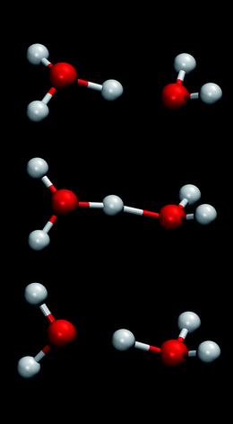 | ||
| Fig. 5 Illustration of proton transport by structural diffusion via a Zundel ion. | ||
Quantum mechanical studies of proton transfer are computationally intensive and are limited to examining the local structure around acid sites. Paddison et al.23,74 used density functional theory (DFT) with Becke's 3-parameter functional (B3LYP)91,92 and the 6–311G(d,p) basis set93 to show that the ether oxygens in the Nafion side-chain (Fig. 3) are not hydrophilic, because of the strong electron withdrawing effect of the two CF2 groups. Systematic addition of H2O molecules to triflic acid73 (taken as a Nafion sidechain analogue) showed that at least three H2O molecules are needed to dissociate the proton from CF3SO3H. When 6 H2O molecules were added, the hydrated proton moved further away from the SO3− group suggesting that with increasing hydration the H2O molecules shield the proton from interaction with the SO3− group. Paddison and Elliott68–72 augmented this study of isolated fragments with subsequent work on the effect of sidechain length and flexibility, backbone conformation and energetics of local hydration on proton transfer. They observed that the number of water molecules required to dissociate the proton from the SO3H group was reduced when these groups were brought closer due to partial folding of the backbone.
While the pioneering electronic structure calculations of Paddison et al.23,68–74 have provided remarkable insights into proton transfer processes in Nafion-like polymer fragments, there remains a need to understand the dynamics of proton transfer from the acid site and recombination with the conjugate base. To address this, Glezakou et al.75 have used AIMD to examine acid–base equilibria of neutral and ion-pair complexes AH: (H2O)n ↔ A−: H+(H2O)n, where A represents CF3CF2SO3. This work used the metadynamics approach of Laio and Parrinello94 using the BLYP functional,95 GTH family of pseudopotentials96 for core electrons and GTH basis sets97 of double-zeta plus polarization quality. Free energy reactive landscapes were obtained by using the hydrogen coordination numbers of the oxygens involved in proton transfer to visualize the dynamic equilibrium between the neutral and ion pair complexes for various n (number of H2O molecules). The proton does not dissociate from the sulfonic acid group for n = 1 and 2. The free energy landscape shown in Fig. 6 for n = 2 has the lowest energy well at water oxygen (Ow) coordination number of ∼2 and sulfonic acid oxygen (Os) coordination number of ∼1, which shows that the proton does not transfer to the H2O molecule. The insets show the structures corresponding to the ion pair (left) and the neutral cluster (right) with the latter having free energy that is lower by 6.5 kcal mol−1. For n = 3, the relative stabilities are reversed. The ion pair was found to be more stable than the neutral complex by 1.5 kcal mol−1 with a small free energy barrier of only 0.5 kcal mol−1. Glezakou et al.75 also observed the formation of a solvent-separated ion-pair for n = 4, and their findings are in good agreement with the electronic structure calculations of Paddison et al.23 A previous AIMD simulation13 of triflic acid monohydrate (λ = 1), corresponding to minimally hydrated PEM, has shown the presence of solvent-separated ion pair and the important role of the Zundel ion (Fig. 5) as a mediator of proton transfer.
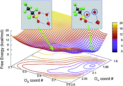 | ||
| Fig. 6 Free energy surface showing the equilibrium between neutral complex (inset left) and ion pair complex (inset right) for two H2O molecules. The collective variables Os and Ow are coordination numbers of sulfonic acid oxygen and water oxygen, respectively.75 Reproduced from ref. 75 by permission of the PCCP Ownership Board. | ||
At the next higher scale, Seeliger et al.76 have examined proton transport in slab-like Nafion (EW = 1100 g mol−1 of SO3) pores for λ = 5 and 10 using the EVB model. The water network was continuous for λ = 10 but discontinuous for λ = 5. The authors concluded that proton transport at these hydration levels is dominated by structural diffusion and the water network percolates only on average with temporarily opening and closing bridges between water clusters as proposed by Vishnyakov and Neimark79 based on classical MD simulations. The Voth group77,78 has generalized the original EVB approach98 by developing a multistate EVB model (MS-EVB) to rigorously model proton solvation and transport. In the MS-EVB model, the identity of the EVB states constantly changes during the simulation, energy is conserved, and the relative importance of vehicular and structural transport of protons can be evaluated. For multiple protons, an extension called the self-consistent iterative MS-EVB (SCI-MS-EVB)78 has been developed that iteratively solves the MS-EVB problem for individual EVB complexes each containing one proton in the effective field of other EVB complexes. SCI-MS-EVB simulations78 for 1100 EW Nafion at λ = 15 showed that the excess proton is in the Zundel configuration in the contact ion-pair position but transitions to the Eigen configuration (H9O4+) in the solvent-separated ion pair position. The vehicular and structural components of proton transport were found to be of similar magnitude but with strong negative correlation leading to a smaller overall diffusion coefficient. This is in marked contrast to the situation in bulk water, where there is no such negative correlation. The proton transport was found to be significantly influenced by SO3− ions, which serve as proton traps.
Urata et al.80 and Cui et al.82 have used classical MD simulations with united-atom force fields for the backbone and all-atom force fields for the side-chain to model hydrated Nafion. United-atom force fields are less rigorous but have the advantage that a larger system can be simulated compared to all-atom force fields. Urata et al.80 observed the aggregation of SO3− groups and binding of H2O molecules to sulfonate groups at low hydration levels (λ = 2.8). At high hydration levels (λ = 35.4), frequent exchange occurred between bound and free H2O molecules. The side-chain was found to preferentially orient perpendicular to the hydrophilic/hydrophobic interface. The residence time of H2O molecules near SO3− groups was found to be ∼1 ps. Cui et al.82 used a force field similar to that of Urata et al.,80 but simulated a shorter Nafion chain with 3 monomers instead of the 10-monomer chain simulated by Urata et al.80 Their simulations revealed that clustering of H2O molecules was strongly dependent on the hydration level. Small isolated H2O clusters formed at low λ and became connected into a single cluster as λ increased. The degree of solvation of H3O+ ions was also found to increase with λ resulting in local structures capable of forming Eigen ions that can facilitate proton transport by the Grotthuss mechanism. Cui et al.82 attributed the poor proton conductivity at low λ to the poor hydration of the H3O+ ion and the lack of connectivity between water clusters. Blake et al.83 have also concluded that the large concentration of ions and small channel size serve to reduce the diffusion of H2O molecules based on their MD simulation of hydrated Nafion with Na+ counterions. While the diffusion coefficient typically reported by MD simulations is due to contributions from molecules in different local environments, Blake et al.83 have shown that H2O diffusion is mainly due to the free H2O molecules in the middle of the channel. This conclusion is consistent with the most recent findings of Paul and Paddison,99 based on a statistical mechanical model of proton transport in PFSA membranes,100 that proton transport occurs mainly in the centre of the Nafion pore, well separated from the sulfonate groups.
While the previous studies have shown the existence of nanophase segregation in hydrated Nafion, the effect of the sequence of polar and non-polar monomeric units on the nanostructure and ionic transport has not been extensively studied. It is difficult to characterize the monomeric sequence experimentally. On the other hand, MD simulations are well suited to examine the role of molecular architecture in determining membrane nanostructure. Jang et al.81 have used all-atom force fields to examine two extreme monomeric sequences of Nafion with an EW of 1150 as shown in Fig. 7. In the dispersed sequence [Fig. 7(a)], the polar groups are uniformly distributed along the chain with a separation of 2.2 nm between adjacent sulfonic acid groups in a fully extended chain. In the blocky sequence, the polar groups are clustered together and the distance between adjacent sulfonic acid groups is 0.6 nm when the chain is fully extended. In reality, Nafion membrane is expected to have sequences that are distributed between these two extremes. For λ = 16, Jang et al.81 found that SO3− groups are more uniformly distributed in the equilibrated MD simulation cell, there is less phase segregation, the hydrophilic domains (H2O clusters and channel) are smaller, the SO3− groups are solvated by more H2O molecules, and the H2O diffusion coefficient is smaller for the dispersed sequence compared to the blocky sequence. This work shows the potential for improving membrane properties by changing the molecular architecture.
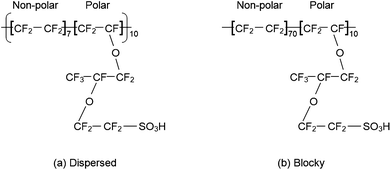 | ||
| Fig. 7 Structure of the Nafion chains studied by Jang et al.81 (a) Dispersed monomeric sequence and (b) blocky monomeric sequence. | ||
Devanathan et al.84–86 used two different all-atom force fields to systematically examine the nanostructure of Nafion of EW 1150 and the dynamics of H2O molecules and H3O+ ions as a function of λ at 300 and 350 K. Eleven levels of hydration over a range of λ from 1 to 20 were examined for a period of 2 ns. These λ values were chosen to facilitate comparison with the experimental studies of Pivovar and Pivovar,35 Perrin et al.39 and Moilanen et al.48,49 Four chains of ten monomers each in the dispersed sequence of Fig. 7(a) were simulated. The ionic form of Nafion was modelled with H3O+ as counterion. While such a classical simulation is incapable of modelling structural transport of protons, it is well suited to study membrane nanostructure and the dynamics of H2O molecules. Analysis of radial distribution functions and coordination numbers revealed that H3O+ ions play a significant role in determining the interfacial structure of the SO3− pendants. At low hydration levels (λ < 7), short hydrogen-bonded linkages constrain the SO3− groups. Most of the H2O molecules and H3O+ ions are strongly bound to the SO3− groups, which impedes proton transport by the vehicular mechanism. Moreover, at low λ, H3O+ ions are surrounded by multiple SO3− groups, which hinder structural diffusion by offering steric hindrance to the hydration of H3O+ ions. A multiply-coordinated H3O+ ion is less likely to become free than a H3O+ ion coordinated by only one SO3− group. In contrast to the strong interaction with SO3− groups, H2O molecules were shown to have a weak interaction with the polymer backbone, in agreement with the conclusion of Perrin et al.101 based on NMR relaxometry. MD simulations show that even the first ether oxygen closest to the SO3− group (Fig. 3) is hydrophobic.85 Thus, the consensus from MD simulations is that the hydrophilic subphase in Nafion is just the sulfonate group at the end of the pendant.79,80,85
Fig. 8 is a plot of the fraction of H3O+ ions that are coordinated by more than one SO3− group as a function of λ. MD simulation results85 (squares) are in excellent agreement with the fraction of non-diffusing hydrogen determined by Pivovar and Pivovar35 using QENS (triangles). The change in slope around λ = 5 provides insights into the “abrupt structural change” inferred by Moilanen et al.48 using IR spectroscopy. As λ increases, the SO3− groups move apart from each other and the H3O+ ions move from the first solvation shell of SO3− groups to the second solvation shell. Even at low λ, the H3O+ ions and H2O molecules are coordinated by different SO3− groups during the 2 ns duration of the simulation. The H3O+ ions and H2O molecules spend some time bound to a SO3− group, subsequently move away towards the centre of the H2O channel and then may become bound to a different SO3− group—even one from a different chain from that of the original SO3− group. This picture is consistent with the temporary opening and closing of bridges between H2O clusters reported by Vishnyakov and Neimark.79
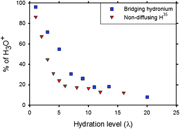 | ||
| Fig. 8 Fraction of H3O+ ions that are surrounded by multiple SO3− groups from simulation85 (squares) and the fraction of non-diffusing hydrogen atoms determined by QENS experiment (triangles).35 Reprinted with permission from ref. 85, copyright 2007, American Chemical Society. | ||
Fig. 9 gives a visual representation of simulated Nafion nanostructure85 by projecting a 4.2 nm by 3 nm simulation cell with depth cuing (darker atoms are closer to the viewer) for six different levels of hydration. H2O molecules, H3O+ ions, SO3− groups and the rest of the membranes are represented by blue, red, yellow and gray, respectively. The trapping of H3O+ ions by multiple SO3− groups for λ = 3 can be clearly seen in the bottom right of Fig. 9(a). With increasing λ, H3O+ ions and the H2O molecules move further away from the SO3− groups and a continuous channel can be seen for λ = 13.5. The maximum displacement of H3O+ ions and H2O molecules from SO3− groups was found to be 0.8 nm and 1 nm, respectively. This is consistent with Schmidt-Rohr and Chen's cylindrical H2O channel model57 with an average diameter of ∼2.4 nm. Schmidt-Rohr and Chen57 have stated that other Nafion models feature constrictions of 0.6 to 1 nm. Such a narrow width is not consistent with H2O molecules venturing 1 nm from the nearest SO3− group.86
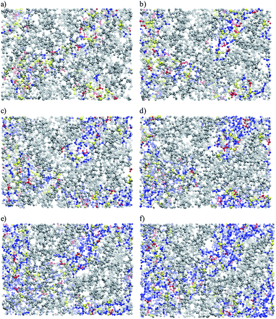 | ||
| Fig. 9 Projection of hydrated Nafion simulation cell for the following λ values: (a) 3; (b) 5; (c) 7; (d) 9; (e) 11 and (f) 13.5.85 Water molecules, hydronium ions and sulfonate groups are shown in blue, red and yellow, respectively. Reprinted with permission from ref. 85, copyright 2007, American Chemical Society. | ||
In addition to structural characterization, recent MD simulations84–86 have also provided insights into the dynamics of H3O+ ions and the H2O molecules in Nafion. Temperature was found to have a significant effect on the diffusion of H3O+ ions and the H2O molecules in the range 300 to 350 K.84 The mean residence times (MRT) of H3O+ ions around SO3− groups were found to be 0.19–0.57 ns in fully hydrated Nafion.86 The QENS results of Perrin et al.39 show that the lifetime of H3O+ ions in Nafion is of the order of 1 ns. Fig. 10 shows the MRT of H2O molecules in Nafion as a function of λ. The residence time decreases from ∼1 ns in nearly dry Nafion (λ = 3) to about 75 ps in fully hydrated Nafion (λ = 20). The simulation data are shown along with the experimentally determined MRT for slow proton dynamics from QENS.39 A note of caution is in order here. MD simulations84,86 show the H3O+ ion diffusion coefficient in well hydrated Nafion is much smaller than the proton diffusion coefficient given by Zawodzinski et al.41 and thus do not support the idea of proton transport exclusively by the vehicular mechanism at all hydration levels. The simulations support interpreting the timescale of the slow proton dynamics observed in the QENS study39 in terms of the binding of H2O molecules to SO3− groups.
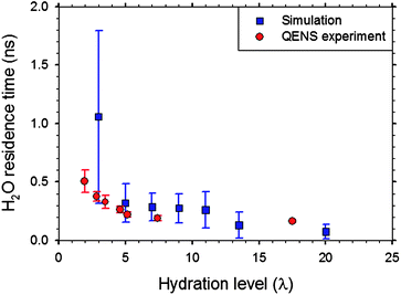 | ||
| Fig. 10 Mean residence time of water molecules in the vicinity of sulfonate groups in Nafion from simulation86 along with the residence time associated with slow proton dynamics observed by QENS.39 Reprinted with permission from ref. 86, copyright 2007, American Chemical Society. | ||
Based on binding to sulfonate groups, one can identify distinct classes of water molecules in Nafion. Devanathan et al.85 have classified H2O molecules into three classes: (i) free or bulk-like H2O; (ii) weakly bound H2O and (iii) H2O molecules bound to SO3− groups. In the literature,54,102,103 water in Nafion membrane has been characterized as (i) freezing, (ii) ‘freezable loosely bound’ or ‘bound freezing’ and (iii) non-freezing, respectively corresponding to the three categories identified above from MD simulation.85 There are scant experimental data on the relative proportions of these states of H2O in Nafion. Cho et al.102 have used thermal analysis to estimate the fraction of non-freezing H2O in Nafion of EW 1100 at λ = 15.1 to be 0.21. Thompson et al.52 concluded from differential scanning calorimetry and conductivity measurements in Nafion of EW 1100 that the fraction of non-freezing H2O at −20 °C remains unchanged with λ for λ > 8. Paul and Paddison104 used a dielectric saturation model with the membrane pore network modelled as cylinders with pendant sulfonic acid groups attached to the walls and protruding into the interior of the pore. The dielectric constant of water was found to be higher near the center of the pore indicating the presence of bulk-like water away from the sulfonic acid group. The fraction of bulk-like water was found to increase with increasing hydration level.
The MD simulations of Devanathan et al.85 have revealed that the fraction of bound (non-freezing) H2O molecules in Nafion of EW 1150 decreases with increasing λ, from 0.82 at λ = 3 to 0.28 at λ = 20 as shown in Fig. 11. This is in reasonable agreement with the value given by Cho et al.102 The change in simulated bound water fraction with λ is less steep at higher λ, which is also consistent with the findings of Thompson et al.52 The fraction of free (freezing) H2O molecules in the simulation increases almost linearly with λ from ∼ 0.03 at λ = 3 to about 0.66 at λ = 20. MD simulation provides an explanation for the persistence of conductivity in Nafion below −20 °C52 in terms of bound water. At temperatures below 0 °C, the effective λ of the membrane is reduced to fBλ, where fB is the bound water fraction. Similar arguments have been made by Thompson et al.,52 who have proposed that free water forms ice cores in the centres of the water channels. Borup et al.103 have stated that chemically bound water in Nafion does not freeze until −120 °C. An improved understanding of bound (non-freezing) vs. free (freezing) water in polymer membranes is needed to gain insights into membrane degradation under freeze–thaw cycles.102 Computational studies of membrane degradation can benefit from coarse grained models that are informed by detailed molecular simulations.89 A recent promising development in modelling MEAs involves the use of reactive force fields to describe membrane chemistry and catalytic reactions with nearly the accuracy of ab initio methods but at a computational cost comparable to that of classical MD.90 Such multi-paradigm multiscale modelling methods have the potential to advance the rational design of PEMs.
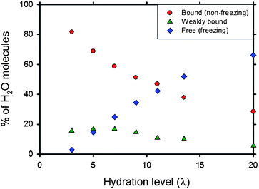 | ||
| Fig. 11 Fraction of chemically bound or non-freezing (circles), weakly bound (triangles) and free or freezing (diamonds) water in hydrated Nafion.85 Reprinted with permission from ref. 85, copyright 2007, American Chemical Society. | ||
3. Other perfluorinated membranes
Several modified perfluorinated and partially fluorinated membranes are being developed to facilitate PEMFC operation under low-humidity and high-temperature (>80 °C) conditions.1053.1 Short-side-chain PFSA membranes
A promising strategy in the quest for membranes that outperform Nafion is to shorten the side-chain length. With a shorter side-chain, such as OCF2CF2SO3H instead of OCF2CF(CF3)OCF2CF2SO3H shown in Fig. 3, one can reduce the EW of the membrane. Proton conductivity is known to increase as EW decreases up to a point, because lower EW results in higher density of acid groups.106 However, low EW membranes are known to have problems with durability and mechanical integrity due to increased swelling.17 The difference between long and short side-chains for the same backbone is shown in Fig. 12 for extended chains in the ionic form. Two adjacent pendants are shown in each case.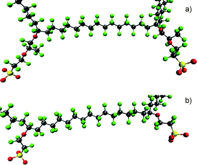 | ||
| Fig. 12 Illustration of a chain of (a) Nafion and (b) short-side-chain membrane for the same backbone length. C, F, S and O are represented by gray, green, yellow and red. | ||
A short-side-chain (SSC) membrane with an EW of 800–900 originally produced by the Dow Chemical Company has been reported to have achieved four times the power of Nafion membrane (EW 1100) at the same operating voltage.107,108 One key advantage of the Dow membrane is higher voltage operation at lower current densities (0.1–0.5 A cm−2) resulting from lower membrane resistance attributed to the high density of sulfonic acid groups.108 Recently, Solvay Solexis Inc. has developed the same SSC membrane of 850–870 EW named Hyflon Ion® using a simpler synthesis route compared to that of the Dow membrane.109–111 Other Nafion-like membranes include Flemion® (Asahi Glass Co. Ltd), Aciplex® (Asahi Chemical Co. Ltd.), 3 M membrane (3 M Inc.) and Gore Select® (Gore and Associates Inc.).109,112,113 SSC membranes are known to have higher crystallinity at a given EW and a higher glass transition temperature compared to Nafion. These characteristics result in higher operating temperature and good mechanical properties for SSC membranes. Thus, SSC membranes are potential candidates for PEMFCs operating in the 80–120 °C temperature range.110
Aricò et al.114 have demonstrated peak power density approaching 0.3 W cm−2 (∼0.9 A cm−2) at 140 °C in a pressurized direct methanol fuel cell with a Hyflon membrane operating with 1 M methanol and air feed. Recently, Merlo et al.115 tested a 25 cm2 direct hydrogen fuel cell with Hyflon Ion-based membrane (870 EW and thickness of 50 μm) electrode assemblies and demonstrated a voltage of 0.75 V at a current density of 0.8 A cm−2 both at 75 °C and 120 °C with air. Membrane durability of 5000 h at 75 °C was demonstrated during PEMFC operation at 0.6 V and an average current density of 1.05 A cm−2. There was no evidence of pinhole formation or membrane thinning. Hydrogen crossover was less than that of Nafion 112 MEA. Proton conductivity of the Hyflon MEA was superior to that of Nafion 112 MEA in sub-freezing conditions down to −40 °C. Information about membrane degradation above 80 °C is not available.
Kreuer et al.111 have compared water sorption, proton conductivity, water diffusion, electro-osmotic drag, microstructure and visco-elastic properties of Dow 858 (EW 858 and thickness ∼80 μm), Dow 1084 (EW 1084 and thickness 90 μm) and Nafion 117 (EW 1100 and thickness 178 μm) membranes. The water diffusion coefficient is nearly the same in all three membranes for λ > 15, but with decreasing hydration it decreases more for the Dow membranes than for Nafion 117. This difference has been attributed to the greater flexibility of the longer side-chain in Nafion.111 At 303 K, Nafion has better proton conductivity than both Dow membranes for λ < 5. For λ > 10 at 303 K, Dow 1084 and Nafion 117 have similar proton conductivity. No significant performance differences were observed between Dow 1084 and Nafion 117. At high hydration levels, Dow 858 has ∼40% higher conductivity than Nafion 117 with similar electro-osmotic drag and methanol cross over. The potential loss across Dow 858 is lower than that across Nafion 117 under all conditions studied. The better performance of Dow 858 has been explained by Kreuer et al.111 in terms of higher ion exchange capacity and higher charge carrier concentration. Recently, Du et al.113 have shown that the performance of PEMFCs with Nafion membrane is significantly enhanced when the membrane thickness is decreased from 178 μm (Nafion 117) to 50 μm (Nafion 112). Some of the differences between the Dow and Nafion membranes observed by Kreuer et al.111 may be due to the difference in thickness.
Du et al.113 have studied PEMFCs with Nafion, Aciplex and Flemion membranes while keeping the membrane thickness nearly the same. A single PEMFC with Nafion 112 (EW 1100 and thickness 50 μm) showed nearly the same performance as a PEMFC with Aciplex 1002 (EW 1000 and thickness 50 μm). A PEMFC with Flemion SH80 (EW 909 and thickness 80 μm) outperformed a PEMFC with Nafion 1135 (EW 1100 and thickness 88 μm) in the high current density (> 0.5 mA cm−2) range, while the performances were similar in the low current density range. The cell resistance was found to be directly proportional to membrane thickness and it was smaller for smaller EW membranes. Considering the relative paucity of experimental data on SSC membranes compared to the case of Nafion, more fundamental studies of SSC membranes are needed to relate the membrane morphology to transport properties and understand degradation mechanisms.
Theory and modelling studies of SSC membranes are not as well advanced as in the case of Nafion. Ab initio calculations of side-chain fragments have been performed by Paddison and Elliott.68–72 These have been supplemented by recent MD simulations using empirical force fields.87,88 Paddison and Elliott70 have used DFT at the B3LYP91,92/6–311G**116 level to study two SSC fragments connected by a fluorocarbon backbone of variable length. They found that the minimum number of water molecules needed to dissociate the proton from the sulfonic acid groups increased as the number of CF2 groups along the backbone increased. The dissociated protons appeared in Zundel-like configurations (Fig. 5) indicating the possibility of structural diffusion even at low hydration levels (λ = 3). As λ increases, Eigen ions form as solvent-separated ions. Side-chain fragments with a kinked backbone, resulting from hydrogen-bonding of the SO3− groups with H2O molecules, exhibited stronger binding to H2O molecules and effected proton dissociation with fewer H2O molecules compared to those with an elongated backbone.73 The stiffest portion of the side-chain is where it attaches to the backbone, while the most flexible portion of the side-chain is the C–S bond. The results of Paddison and Elliott68–72 show the important roles played by side-chain separation, side-chain flexibility and backbone conformation in proton dissociation in model SSC fragments.
Brandell et al.87 used classical MD simulations to compare Nafion with PFSA membranes having the same backbone (13 CF2 units) but longer (Aciplex) or shorter (Dow) side-chain lengths for λ = 5 and 15. They observed that atomic mobility increases along the side-chain, with the SO3− group having the highest mobility in agreement with the ab initio results of Paddison et al.72 At λ = 15, Nafion was found to have a more uniform water network and the widest water channels. The highest molecular mobility was observed in Nafion leading to the conclusion that Nafion represents the ideal side-chain length to promote side-chain motion and hence molecular motion.87 However, this conclusion is difficult to reconcile with the observation that the highest proton mobility occurs away from the SO3− group in the centre of the H2O channels.83,99,104 Recent classical MD simulations88 of a SSC membrane (EW 580) show that SSC membranes may have a greater number of free H3O+ ions at the same λ compared to Nafion. This offers a plausible explanation for the higher conductivity of PFSA membranes with lower EW. Structural diffusion of protons has to be included in the model to get a better understanding of differences in proton transport arising from differences in side-chain length.
3.2 PFSA membranes containing inorganic fillers
An interesting approach to improve proton transport and mechanical properties of PFSA membranes at temperatures above 100 °C is to incorporate inorganic materials as fillers in the polymer matrix.117 The dispersion of hygroscopic materials in PFSA membranes can aid water retention for operation at high temperatures and low relative humidity. Antonucci et al.118 demonstrated the use of a Nafion–silica composite membrane in a DMFC at 145 °C with a peak power density of 0.24 W cm−2. They observed improved water retention and low methanol crossover. Mauritz and Payne119 have stated that the surface hydroxyl groups in Nafion-silica composite membranes can strongly attract H2O molecules through hydrogen-bonding as illustrated in Fig. 13. This hydrogen-bonded network can facilitate proton hopping with the aid of bulk liquid-like H2O molecules in successive hydration layers. Adjemian et al.120 introduced the oxide by sol–gel processing, which enabled the incorporation of silica within a preformed Nafion membrane as opposed to recasting silica particles with Nafion solution. In a PEMFC performance comparison120 between Nafion 115–silica composite membrane (6 wt% silica loading) and Nafion 115 membrane at 130 °C, the former maintained performance after 50 h while the latter failed within one hour. This shows that the improved water retention of composite membranes is not transitional. The composite membrane gained 50 °C in operating temperature without a significant decrease in current density. Thus, it exhibited nearly the same hydration level at 130 °C and 3 atm as the unmodified Nafion 115 membranes did at 80 °C and 1 atm.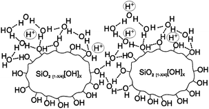 | ||
| Fig. 13 Illustration of proton hopping along hydrogen-bonded pathways structured around high surface/volume silicate nanoparticles that are grown within the sulfonic acid clusters of Nafion.119 Reprinted from ref. 119, copyright 2000, with permission from Elsevier. | ||
Ye et al.44 have studied proton dynamics in Nafion–SiO2 composites using NMR. They prepared the composite membrane by permeating Nafion with a mixture of water and tetraethyl orthosilicate (TEOS) and treating the membrane at 170 °C to drive off physisorbed silica. The molar ratio of H2O : TEOS and permeation time were varied to control the amount of silica in the composite. They found that low concentration of TEOS or short permeation times resulted in complete hydrolysis of TEOS in Nafion and better water retention. Silica in Nafion was found to have two opposing effects. At low TEOS concentrations, small silica particles with no residual ethyl groups form along with a hydrogen-bonded network (Fig. 13) that retains H2O molecules and enables proton transport. This is desirable for elevated temperature operation. At high TEOS concentrations, the silica particles are larger and have residual ethyl groups. These large particles disrupt the hydrogen-bond network and block the pathways for proton transport. Tang et al.121 have synthesized Nafion–SiO2 composite membranes by a self-assembly process using TEOS precursor. The SiO2 nanoparticles had an average particle size of 2.8 ± 0.5 nm. This composite membrane was found to have enhanced durability compared to conventional Nafion–SiO2 composite membrane and pristine Nafion membrane under accelerated wet/dry cyclic tests at 90 °C. Recently, hybrid membranes of Nafion and mesoporous silica containing sulfonic acid groups have been synthesized by the sol–gel process and found to have better dimensional stability and proton conductivity at 95 °C compared to Nafion 112.122 With increasing silica content, the ion exchange capacity decreased while the water uptake increased. The optimal silica content was determined to be 13 wt%. The high surface area of mesoporous silica and presence of hydrophilic sulfonic and silanol groups inside the mesopores enhance the water uptake. Controlling the processing to attain the desired filler particle size and distribution is a key objective in the development of composite membranes.
Uchida et al.123 impregnated Nafion 112 membrane with TiO2 nanoparticles in an effort to develop a self-humidifying PEM. A uniform distribution of 2–4 wt% TiO2 along with Pt in the membrane was achieved using in situ reactions. Pt nanoparticles were included to suppress fuel crossover by catalytic recombination of H2 and O2. TiO2 nanoparticles serve to adsorb the water produced at Pt particles and by the cathode reaction. The Pt–TiO2–Nafion membrane was used in a PEMFC operated at 80 °C and ambient pressure in dry H2 and O2 after drying the cell overnight with dry N2. No external humidification was used. It was observed that the hygroscopic TiO2 nanoparticles enhance the back-diffusion of H2O molecules generated at the cathode, resulting in a water balance between the anode and cathode. The peak power density was 0.78 W cm−2. However the structure and chemistry of the electrolyte need to be optimized to realize the potential of self-humidifying membranes.
Choi et al.124 have observed improved water uptake at 90 °C in Nafion–sulfated zirconia nanocomposites prepared by sol–gel processing compared to that in unmodified Nafion. The authors also developed a thermodynamic model to understand proton transport in the composite membrane. The improved proton conductivity of the composite membrane was attributed to increased water uptake and the availability of additional acid sites. The proton conductivity of Nafion is expected to be improved by 20% with the incorporation of sulfated zirconia nanoparticles if the particle size and distribution are carefully controlled.124 Aricò et al.125 prepared composite membranes of recast Nafion containing nanoparticle fillers of SiO2, ZrO2 or Al2O3 to study the effect of surface chemistry on membrane properties. All of these oxide fillers were found to improve water retention in the range 90–145 °C. For DMFC operation with 2 M methanol at 2.5 atm and 145 °C, the highest power density was attained with Nafion–SiO2 and lowest with Nafion–Al2O3. Oxides with stronger acidic surface functionalities were found to better retain water.
Yang et al.126 have studied Nafion 115 composite membranes with 25 wt% zirconium phosphate fillers. Zr(HPO4)2·H2O was chosen as the additive because it is a proton donor, chemically compatible with Nafion, hygroscopic and hydrophilic, and thermally stable at the desired membrane operating temperature. Proton conductivity is poorer but fuel cell performance is improved for the composite membrane compared to that of Nafion 115. At 80 °C, the fuel cell performance of the two membranes was comparable, but at 130 °C the composite membrane had clearly superior performance with a peak power density of about 0.4 W cm−2. In the literature one often finds tables of data listing the conductivity of various membranes. The results of Yang et al.126 show that membranes should not be evaluated based only on conductivity data. The authors126 proposed based on SAXS data that the zirconium phosphate acts primarily as a scaffold that maintains dimensional stability when water is removed and enhances water uptake but does not play a direct role in proton conductivity. A recent NMR study127 has examined the effects of the addition of SiO2, TiO2, or Zr(HPO4)2 to Nafion. Each of these additions resulted in improved water uptake and improved PEMFC performance compared to unmodified Nafion. The authors127 attribute the enhanced water uptake not to the hygroscopic nature of the fillers but instead to modifications of the membrane pore structure leading to larger cavities for water clustering.
Chen et al.128 have used in situ hydrothermal crystallization to synthesize Nafion–acid-functionalized zeolite nanocomposite membranes with 5 wt% loading of fillers in the form of nanocrystals of diameter ∼20 nm. These membranes had similar proton conductivity but 40% lower methanol permeability compared to Nafion 115 membranes. Lepiller et al.129 have synthesized composite membranes with 5 wt% RuO2·xH2O, a mixed electronic–protonic conductor, as an additive to Nafion. The measured conductivity was unchanged with relative humidity and was much higher than the conductivity of unmodified Nafion. This high conductivity was most likely due to electronic conductivity arising from a sedimentation layer of RuO2·xH2O on one side of the membrane. There is a need for better understanding of the effect of the inorganic fillers on membrane morphology.
Several recent studies have examined the possibility of improving PFSA membrane performance by including heteropoly acids (HPAs).130–132 HPAs are superacidic inorganic oxides that exhibit excellent proton conductivity in the solid state and interact strongly with sulfonic acid groups when incorporated in PFSA membranes. Two commonly used HPAs are 12-phosphotungstic acid (H3PW12O40 or PTA) and 12-silicotungstic acid (H4SiW12O40 or STA). Ramani et al.130,131 prepared Nafion membranes with 25 wt% loading of stabilized nanoparticles of PTA and demonstrated their use in MEAs at 120 °C at 35% RH. Meng et al.132 have doped a PFSA membrane with STA and PTA and observed improved proton conductivity up to a temperature of 120 °C. The influence of HPAs on proton transport is not clear from these studies. While there appears to be a consensus that hydrophilic fillers can enhance water uptake and enable elevated temperature operation, the nanostructure of composite membranes and proton transport mechanisms are poorly understood. Fundamental theoretical studies extending from molecular to continuum models are needed to optimize filler particle size and surface chemistry for the desired composite membrane performance.
3.3 Polystyrene sulfonic acid (PSSA) membranes
PSSA membranes are a promising low-cost alternative to PFSA membranes. Ballard Power Systems has developed a partially fluorinated PEM based on trifluorostyrene and substituted trifluorostyrene compositions.133,134 PEMFCs have been operated with Ballard membranes for over 15000 h and the use of a PSSA–Nafion composite membrane has been demonstrated in a PEMFC operating at 80 °C for 835 hours.135 The chemical structure of the BAM3G (Ballard Advanced Materials 3rd Generation) membrane is illustrated in Fig. 14(a). This low-cost membrane is reported to perform as well as commercial PFSA membranes with excellent durability.135 Unlike the short-side-chain membranes or the composite membranes with oxide or heteropoly acid fillers, very little data are available in the literature about the exact chemical composition, morphology, conductivity, chemical stability and mechanical properties of BAM membranes. This is a serious impediment to theoretical studies that have the potential to aid PSSA membrane development.
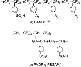 | ||
Fig. 14 Chemical structure of (a) α,β,β-trifluorostyrene membrane.134 A1, A2 and A3 are selected from the following groups: CF![[double bond, length as m-dash]](https://www.rsc.org/images/entities/char_e001.gif) CF2, CN, NO2, OH, O–CxHyFz (where x > 3 and y + z = 2x + 1) and aryls; (b) radiation grafted PVDF-g-PSSA membrane.137 CF2, CN, NO2, OH, O–CxHyFz (where x > 3 and y + z = 2x + 1) and aryls; (b) radiation grafted PVDF-g-PSSA membrane.137 | ||
Beattie et al.136 have compared the performance of BAM membranes of a wide range of EWs with that of Nafion 117 membrane. They studied BAM membranes with EW of 407, 436, 455, 509, 542 and 735. EW of 509 appears to be optimal from the standpoint of conductivity. The room temperature conductivity of fully hydrated BAM membrane was 0.17 S cm−1 for EW 509 at a water content of 55.9 vol%, which corresponds to λ = 33. The conductivity appears to be highly sensitive to water content. BAM membranes with lower EW have lower conductivity because of the dilution of the acid by large water uptake (λ ≈ 100), while higher EW membranes have lower conductivity because of poor water uptake (λ ≈ 10). The styrenic side-chains of BAM membranes are considered to be much more rigid than Nafion side-chains.136 Analysis of SAXS data136 suggest that sulfonic acid groups are distributed uniformly throughout the membrane. The phase separation into hydrophilic and hydrophobic domains in BAM membranes is not as well developed as in Nafion membranes. The lack of side-chain flexibility is considered to inhibit the aggregation of ionic sites. A large fraction of the water in the membrane is not associated with ionic aggregates. Thus, the proton conductivity mechanism may be different in BAM membranes and Nafion. Non-fluorinated partially aliphatic analogues of the BAM membranes are known to have shorter lifetimes due to peroxide formation. For instance, membranes based on block copolymers of styrene-ethylene/butylene-styrene are known to have poor oxidative stability compared to PFSA membranes.24
Siu et al.137 have examined the morphology and water uptake of a novel polymer membrane prepared by radiation grafting. Poly(vinylidene fluoride) or PVDF was grafted with poly(styrenesulfonic acid) or PSSA using γ radiation. The chemical structure of the resulting PVDF-g-PSSA membrane is shown in Fig. 14(b). The membrane pore structure is not known. At low λ, the ionic network is considered to be poorly developed leading to poor proton conductivity. Increasing the density of the hydrophilic pendants increases the proton conductivity but results in greater methanol permeability, which is attributed to higher free water content. Tsang et al.138 have examined the role of macromolecular structure in polystyrene membranes by comparing the water uptake and proton conductivity of graft and diblock polymers of similar composition containing fluorous and polystyrene segments. The graft copolymer contained highly concentrated, isotropically-connected ionic domains and a cohesive hydrophobic matrix that resisted swelling. On the other hand, the diblock polymer underwent excessive swelling and had poorer mechanical properties due to the lamellar nature of the membrane. Proton conductivity in the through-plane direction that is relevant to PEMFC operation was lower in the diblock membrane. The experiments of Tsang et al.138 and the simulations of Jang et al.82 show that the molecular architecture is an important factor in PEM design. A key message from recent studies126,136 is that conductivity is only one factor to be considered in membrane selection. Water and methanol transport, chemical and mechanical stability, durability under fuel cell operating conditions, compatibility with electrode materials, processability and cost are other important factors to be considered.
4. Aromatic backbone membranes
Aromatic hydrocarbon-based membranes are a promising alternative to Nafion for elevated temperature operation because of low cost, processability, wide latitude to tune the chemistry, and mechanical, thermal and oxidative stability. Several reviews have identified novel polymers with aromatic backbone for use in PEMFCs.12,15,19,24,26 Linked benzene rings are known to produce rigid polymers that are unsuitable for PEMs while the addition of ether links to benzene rings imparts much-needed flexibility and oxidative stability.15 Polyetheretherketone (PEEK), polyethersulfone (PES) and polybenzimidazole (PBI) have been extensively studied by experiment. The hydrocarbons are sulfonated to impart proton conductivity. A recent ab initio study139 of the choice of protogenic group in PEMs compared sulfonic acid, phosphonic acid and imidazole functionalized alkanes. The energy penalty for proton transfer was highest for imidazole and lowest for phosphonic acid. The study also revealed that sulfonic and phosphonic acid-functionalized membranes would retain water better under low-humidity conditions compared to imidazole-functionalized membranes. However, a very high concentration of phosphonic acid groups is required to achieve high proton conductivity.140 The lower acidity of phosphonic acid compared to sulfonic acid lowers the hydrophilicity, water uptake and proton conduction. It is not surprising that sulfonic acid is widely used as the protogenic group in PEMs.Several studies19,36,43 have compared the morphology of Nafion and sulfonated polyetheretherketone (SPEEK) and concluded that pathways for water and methanol permeation are narrower in the latter. The difference between the two membranes was inferred from the results of SAXS experiments and is illustrated in Fig. 15. The ionomer peak of SPEEK is broadened and shifted towards larger q and I(q) at large q is higher compared to the corresponding values of Nafion. This indicates narrower water channels in SPEEK with more branches and dead-end channels leading to poorer connectivity.19 The morphological differences arise from the backbone rigidity and the lack of side-chains in SPEEK.43 The SO3− groups are separated by a greater distance in SPEEK and the pKa is about −1 compared to −6 for the superacid Nafion (pKa = −log10Ka, where Ka is the acid dissociation constant). Due to these differences, the decrease in proton conductivity with decreasing λ is much more drastic in SPEEK than in Nafion. One needs much higher ion exchange capacity in SPEEK to attain proton conductivity comparable to that of Nafion. However, high ion exchange capacity SPEEK membranes suffer from high water uptake, excessive swelling at high λ and poor mechanical properties. Moreover, SPEEK membranes are brittle at very low λ. These disadvantages can be overcome by blending with other polymers or crosslinking.19
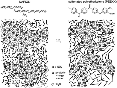 | ||
| Fig. 15 Schematic representation of the morphology of Nafion and sulfonated polyetheretherketone membranes based on SAXS data. Reprinted from ref. 19, copyright 2001, with permission from Elsevier. | ||
Liu et al.141 have synthesized several low-cost sulfonated polyetherketones (SPEKs) by substitution of phenyl, methylphenyl, trifluoromethylphenyl and phenoxylphenyl groups. The sulfonic acid group was attached to the main chain or a side group as in the case of phenylated SPEKs. The degree of sulfonation (DS) of homopolymers was varied by polymerization of bisphenol monomer with phenyl ketone monomers of different lengths. Co-polymers of varying DS were synthesized by preparing different ratios of segments that are readily sulfonated and segments that are not sulfonated. Of the twelve SPEKs examined, Ph-SPEEKDK [Fig. 16(a)] and Me-SPEEKDK [Fig. 16(b)] were the most promising membrane materials. The swelling ratios of these two homopolymers was 15% at 100 °C, while the other polymers had much higher swelling. All the SPEKs had higher tensile strength and lower elongation than Nafion 117 in wet and dry conditions. The methanol permeability of Ph-SPEEKDK and Me-SPEEKDK was 0.06 and 0.15 times that of Nafion 117, respectively. The proton conductivity of Ph-SPEEKDK and Me-SPEEKDK was 0.58 and 0.64 times that of Nafion 117 at 100 °C. These two polymers showed good oxidative stability after 6 h in Fenton's reagent at 80 °C.141 Fuel cell performance data is not available for these membranes.
 | ||
| Fig. 16 Chemical structure of (a) Ph-SPEEKDK and (b) Me-SPEEKDK synthesized by Liu et al.141 | ||
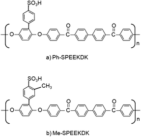
McGrath and coworkers have synthesized a series of thermally stable hydrophilic–hydrophobic multiblock copolymers for PEM applications.24,142–146. In these copolymers the hydrophilic block with SO3H groups enhances proton conductivity, while the hydrophobic block provides mechanical strength and thermal stability. By varying the lengths of the blocks, the membrane morphology can be controlled. An example of such a copolymer is bisphenol-based wholly aromatic random poly(arylene ether disulfonated sulfone)/poly(arylene ethersulfone) referred to as BPSH-xx. The chemical structure of BPSH-xx is shown in Fig. 17(a). xx refers to the mole fraction of disulfonated monomer. As xx increases, the DS increases and there are significant changes in membrane morphology.24 The conductivity and water uptake also increase with xx, but beyond xx = 50, the membrane swells excessively and the resulting hydrogel is unsuitable as a PEM. Kim et al.143 have used DSC and NMR to investigate the state of water in Nafion and BPSH-xx. The fraction of water that is bound (non-freezing) was 0.40, 0.33, 0.34, 0.28 and 0.11, respectively for BPSH-10 (λ ≈ 8), BPSH-20 (λ ≈ 11), BPSH-30 (λ ∼ 12), BPSH-40 (λ ≈ 18) and Nafion 1135 (λ ≈ 20). The increased local viscosity of water has been used to explain the lower electro-osmotic drag and methanol permeability in BPSH membranes compared to the case of Nafion.143
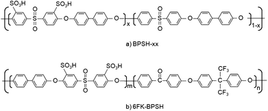 | ||
| Fig. 17 Chemical structure of hydrophilic-hydrophobic multiblock copolymers synthesized by the McGrath group. (a) BPSH-xx24 and (b) 6FK-BPSH.145 | ||
Since random copolymers with statistically distributed SO3H groups are known to form isolated hydrophilic domains at low λ resulting in poor membrane performance, the McGrath group has recently synthesized multiblock copolymers with tailored backbone structure.146 The chemical structure of this novel 6FK-BPSH copolymer based on a hydrophobic fluorine-terminated polyarylene ether ketone block and a hydrophilic disulfonated polyarylene ether sulfone block is shown in Fig. 17(b). The molecular weight of the two blocks is nearly the same to establish good connectivity between hydrophilic domains even at low λ. The proton conductivity of 6FK-BPSH was comparable to that of Nafion 112 over a wide range of RH and temperature. Preliminary fuel cell performance tests show that 6FK-BPSH performs as well as Nafion at 80 °C.146 Moreover, there is potential to improve the performance of 6FK-BPSH membranes if compatible electrode materials are developed.
Matsumura et al.147 have reported the development of branched PEKs with hexaphenylbenzene moieties and end groups bearing clusters of SO3H. The water uptake and proton conductivity are comparable to those of Nafion 117. The membrane has a highly phase-separated morphology with ionic clusters smaller than those of Nafion. Miyatake and Watanabe148 have proposed a high temperature membrane based on a sulfonated polyimide with branching tris(aminoethyl) amine segments. The chemical structure of this hybrid aromatic–aliphatic membrane is shown in Fig. 18. The flexible alkyl chains make this membrane more resistant to hydrolytic attack during fuel cell operation compared to wholly aromatic membranes. Fuel cells using this new membrane have been operated without degradation for 5000 h at 80 °C. While the proton conductivity at 80 °C is comparable to that of Nafion 112 at high RH, it is poor at low RH (<40 %). In addition to the membranes discussed above, several other promising wholly aromatic membranes have been covered by previous reviews.15,24,26 Efforts to tailor the polymer architecture to achieve desired membrane properties at low RH can benefit from theoretical studies of membrane morphology, proton dissociation, proton transport and water network formation. However theory and modelling studies have mostly focussed on Nafion-like membranes.
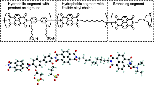 | ||
| Fig. 18 Chemical structure (top) and ball and stick model (bottom) of sulfonated copolyimide with pendant acidic groups and flexible aliphatic main chains. Reprinted from ref. 148 with the permission of the Royal Society of Chemistry. | ||
As in the case of Nafion, inorganic fillers have been added to poly aromatic membranes to improve fuel cell performance. Sulfonated, silylated and cross-linked PEEK membrane was found to have water uptake comparable to that of Nafion.149 However, the proton conductivity was an order of magnitude lower than that of Nafion at 25 °C. Amino-functionalized silica (SiO-NH2) has been introduced into SPEEK membranes to improve water retention at elevated temperatures.150 The water uptake and swelling were reduced compared to unmodified SPEEK without detrimental effect on proton transport. The composite membrane was tested in a PEMFC operating at 120 °C. The peak power density was ∼0.25 W cm−2 for SPEEK with functionalized silica compared to ∼0.18 W cm−2 for unmodified SPEEK. The McGrath group151 has prepared composite membranes of BPSH-40 with zirconium hydrogen phosphate filler by in situ precipitation. The protonic conductivity of the composite membrane with 30% filler was lower than that of BPSH-40 at 25 °C but higher at temperatures above 80 °C. This indicates that the filler stabilizes membrane swelling and reduces water dilution. The methanol permeability was also lower for the composite membrane. An earlier study152 by this group had found that the incorporation of phosphotungstic acid reduced the swelling of BPSH membranes without decreasing proton conductivity. The proton conductivity of the composite membrane was 0.15 S cm−1 at 130 °C. While there has been a surge of interest in aromatic backbone membranes for low RH conditions, the long-term stability of these membranes under the harsh elevated temperature PEMFC operating conditions remains to be explored.
5. Anhydrous membranes
Proton exchange membranes that operate without water above 120 °C can bring about revolutionary advances in PEMFC technology. Many of the current concerns about catalyst poisoning by CO, membrane swelling and water management will not be limiting factors for such membranes. Anhydrous membranes need not be completely dry. They are typically expected to function above 100 °C without external humidification.153 Several different strategies are being pursued for achieving proton conduction in water-free membranes.One approach to develop anhydrous membranes is to replace water as the proton solvent with a liquid that has a higher boiling point. Imidazole and phosphoric acid are promising proton solvents, because they exhibit a high degree of self dissociation and are amphoteric. Membranes containing imidazole as proton solvent have been synthesized with conductivity of 0.1 S cm−1 at 160–180 °C, but fuel cells based on such membranes failed to generate any current due to poisoning of the Pt catalyst by imidazole.154 Novel polymers with imidazole tethered to a polysiloxane backbone via flexible alkyl spacers have shown a relatively low proton conductivity of 1.5 × 10 − 3 S cm−1 at 160 °C.155 In this system, correlated proton transfers give rise to proton hopping that does not contribute to proton conductivity (analogous to proton hopping along a circular trajectory).
Polymer membranes with basic sites have been impregnated with various acids with decidedly mixed results. Acid leaching from the membrane, corrosion of cell components, and adsorption of anions on catalysts are some of the problems with this approach.156 Most of the acid–base blend systems studied have proton conductivity less than 10 − 3 S cm−1 at 300 K. The Savinell group157 has performed extensive studies of polybenzimidazole (PBI) doped with phosphoric acid (H3PO4) for use in PEMFCs operating at elevated temperature (120–200 °C). PBI is a basic polymer with excellent mechanical and chemical stability in this temperature range and H3PO4 is a weak acid that supports conductivity in anhydrous conditions by forming a hydrogen-bonded network.
When PBI is doped with H3PO4, the protonic conductivity increases with doping level, temperature and humidification.158 The doping level is expressed in terms of the number of molecules of H3PO4 per repeat unit of PBI and the optimum doping level is around 5.159 At low doping levels, the conductivity is poor while at high doping levels the mechanical strength is adversely affected.159 The mechanical properties can be improved without compromising the conductivity by increasing the molecular weight of the polymer.160 Even at the same doping level, membrane performance is influenced by the method of membrane preparation.157 Proton transport is believed to take place by a two step process. First, the solvent molecules reorient to form hydrogen bonds in a slow process and then the proton hop occurs by the Grotthuss mechanism along the hydrogen-bonded network. The transport is faster in the presence of H2O.157 H2O molecules help proton conductivity by enhancing the dissociation of the acid and increasing the number of charge carriers. This result can be achieved without external humidification through diffusion of water produced at the cathode.
Recently, H3PO4-doped PBI membranes have been tested in a fuel cell under ambient pressure and 0% RH.161 The peak power density increased linearly from 0.37 W cm−2 at 120 °C to 0.54 W cm−2 at 200 °C. Xiao et al.162 have used sol–gel processing to achieve a high level of H3PO4 doping of PBI with stable mechanical properties and high ionic conductivity at elevated temperature. A 250 μm thick PBI membrane with a H3PO4 doping level of 32 was tested in a fuel cell for 1200 h at 160 °C without humidification of H2 or O2. The peak power output at 160 °C was 0.8 W cm−2 at a current density of 1.4 A cm−2. Zhai et al.163 have prepared a novel H3PO4-doped Nafion–PBI composite membrane and found it to be more durable in fuel cell tests compared to the H3PO4-doped PBI system. Composite membranes of H3PO4-doped PBI with silica filler have been prepared and found to have nearly an order of magnitude better conductivity than the corresponding membrane without filler.164 The hydroxyl groups attached to the silica fillers are believed to offer additional paths for proton hopping in this composite membrane. Qi and Buelte165 have identified several challenges associated with the development of reliable PBI-based PEMFCs. These include adsorption of phosphate anions on the catalyst, high corrosion rate of the amorphous carbon catalyst support, dissolution and sintering of catalyst particles at high temperature and accelerated degradation of the MEA due to open circuit voltage in the no-load state.
A second approach to develop anhydrous membranes is based on a polymer matrix containing protic ionic liquids (PILs). PILs are low-melting analogs of molten salts and feature proton transfer from a Brønsted acid to a Brønsted base.166–168 For instance, the widely studied PIL ethylammonium nitrate forms by
| CH3CH2NH2 + HNO3 → CH3CH2NH3+ NO3−. |
The melting point of PILs is generally below 100 °C. PILs are thermally stable, non-volatile and environmentally benign. There are millions of binary and 1018 ternary ionic liquids,167 which attests to the potential of PILs in anhydrous PEMs.
An acid–ionic liquid–polymer composite gel membrane has been prepared with a PBI matrix containing H3PO4 and the PIL 1-methyl-3-propyl-methylimidazolium dihydrogen phosphate by solution casting.169 The membrane was flexible and free standing with good thermal stability up to 200 °C. The conductivity was ∼0.002 S cm−1 at 150 °C and 0% RH. The conductivity improved with increasing RH. This suggests that the conductivity will be higher in an operating fuel cell, because water will be produced as a by-product. Proton transport is believed to occur along an extensive three-dimensional hydrogen-bonded network. Fernicola et al.170,171 have incorporated a series of PILs in a poly(vinyldene fluoride-co-hexafluoropropylene) (PVdF-HFP) matrix. The conductivity of the resulting membrane at 140 °C was less than 0.01 S cm−1. However, the membranes suffered drastic weight loss when tested in Fenton solution (3% H2O2 and 2 ppm Fe2+ aqueous solution) probably due to loss of the PIL component.
Che et al.172 have incorporated the PIL trifluoroacetic propylamine (TFAPA) in SPEEK and PVdF membranes. The conductivity of SPEEK membrane containing 70 wt% TFAPA was 0.019 S cm−1 at 160 °C. The membrane was thermally stable up to 190 °C, but the mechanical properties need to be improved especially at elevated temperatures. The mechanical strength decreased with increasing temperature and PIL content. Cross-linking offers the possibility of improving the mechanical properties of SPEEK membrane. Recently, diethylmethylamine– trifluoromethanesulfonic acid (dema-TfOH) has been identified as a promising PIL for anhydrous membranes.173 The chemical structure of dema-TfOH is shown in Fig. 19. The ionic conductivity at 120 °C was found to be 0.043 S/cm. Proton transport in these PILs is believed to occur by the vehicular mechanism.170,173 The dissociated proton is expected to be transported with the dema. The possible occurrence of proton hopping, the role of molecular reorientation in proton transfer and the time scale of these processes is of great interest. Dema-TfOH remains in the liquid state over a wide temperature range (melting point is −13 °C) and has good thermal stability. Fuel cell performance was found to be better than that of anhydrous H3PO4 at 150 °C.
 | ||
| Fig. 19 Chemical structure of triflic acid (left) and diethylmethylamine (right). C, H, N, F, S and O are shown as black, white, blue, green, yellow and red spheres, respectively. | ||
A third approach to develop anhydrous membranes is to use solid acids. Solid acid fuel cells feature a non-polymeric electrolyte and operate in the temperature range 200–300 °C. Caesium dihydrogen phosphate, CsH2PO4, is a solid acid that conducts protons above the superprotonic transition temperature (230 °C). The conductivity of CsH2PO4 is 0.022 S cm−1 at 240 °C.174 Solid acid fuel cells with 25 μm thick CsH2PO4 membrane have been fabricated and operated at 240 °C with a peak power density of 0.41 W cm−2.175 The cell performance was not stable for this thin membrane, while thicker membranes (260 μm) have survived fuel cell operation for 100 h. Solid acid fuel cells may be more robust and require a smaller loading of precious metal catalysts compared to polymer membrane fuel cells.176 Much work remains to be done to understand anhydrous proton transport and membrane degradation at elevated temperature.
6. Summary and outlook
Several decades of PEM research have resulted mostly in a phenomenological understanding of membrane performance. Nafion, despite its high cost and hydration requirement that restricts operation to 80 °C, continues to be the most widely studied and deployed membrane for PEMFCs. Even with the extensive experimental database on Nafion membrane structure and molecular transport, our understanding of the water network and proton transport processes is still evolving. The recently proposed parallel cylindrical water channel model and multiscale modelling and simulation studies have helped in the interpretation of experimental data. The hierarchical structure of the membrane necessitates the use of multi-paradigm models from ab initio to mesoscale to study phenomena at different scales.Several promising candidates to replace Nafion have been developed and demonstrated in laboratory-scale tests. The synthesis efforts appear to be following three paths. First, fully or partially perfluorinated membranes can overcome some of the shortcomings of Nafion. Modification of side-chain and backbone length or addition of inorganic fillers and heteropoly acids may help retain water at low-humidity. However, the effect of fillers on membrane morphology is not well understood. Polystyrene sulfonic acid membranes are also emerging as alternatives to Nafion. Second, novel membranes are being developed for low-humidity operation based on aromatic backbone polymers. Excessive swelling is a problem for some of these membranes. Hydrophilic–hydrophobic multiblock copolymers are an interesting step forward in the rational design of PEMs. Third, anhydrous membranes are being developed based on substitution of phosphoric acid, tethered imidazole and protic ionic liquids for water. Leaching of these liquids, dissolution and sintering of catalyst particles at elevated temperature, and mechanical stability of polymer gel electrolytes are serious concerns.
Integrated experimental, theoretical and computational studies that link proton transfer, hydrogen-bonding, molecular transport, membrane morphology and mechanical properties are needed for rational development of the next generation of PEMs. Proton conductivity is not the only consideration in membrane development, although it is the most widely cited metric. Morphological stability, mechanical properties, resistance to degradation upon prolonged operation, processability, compatibility with electrode materials and cost are important considerations. Real world tests of novel membranes during prolonged operation at elevated temperature, low-humidity and oxidizing conditions are needed to rigorously evaluate the membranes proposed as alternatives to Nafion.
Acknowledgements
This work was supported by the US Department of Energy's (DOE) Office of Basic Energy Sciences, Chemical Sciences program under the Hydrogen Fuel Initiative. Pacific Northwest National Laboratory is operated by Battelle for DOE.References
- G. W. Crabtree and M. S. Dresselhaus, MRS Bull., 2008, 33(4), 421–428 CAS.
- G. W. Crabtree, M. S. Dresselhaus and M. V. Buchanan, Phys. Today, 2004, 57, 39–44 CrossRef CAS.
- J. A. Carpenter Jr., J. Gibbs, A. A. Pesaran, L. D. Marlino and K. Kelly, MRS Bull., 2008, 33(4), 439–444.
- F. Barbir, PEM Fuel Cells: Theory and Practice, Elsevier Academic Press, New York, 2005 Search PubMed.
- J. Marcinkoski, J. P. Kopasz and T. G. Benjamin, Int. J. Hydrogen Energy, 2008 DOI:10.1016/j.ijhydene.2007.12.068 , in press.
- E. J. Carlson, P. Kopf, J. Sinha, S. Sriramulu and Y. Yang, National Renewable Energy Laboratory Subcontract Report, NREL/SR-560–39104, 2005, http://www.nrel.gov/hydrogen/pdfs/39104.pdf Search PubMed.
- http://www.scopus.com, search performed on April 4, 2008.
- W. G. Grot, US Pat., 3718627, 1968.
- K. A. Mauritz and R. B. Moore, Chem. Rev., 2004, 104, 4535–4585 CrossRef CAS.
- S. Banerjee and D. E. Curtin, J. Fluorine Chem., 2004, 125, 1211–1216 CrossRef CAS.
- F. Bauer, S. Denneler and M. Willert-Porada, J. Polym. Sci., Part B: Polym. Phys., 2005, 43(7), 786–795 CrossRef CAS.
- J. Rozière and D. J. Jones, Annu. Rev. Mater. Res., 2003, 33, 505–555.
- M. Eikerling, S. J. Paddison, L. R. Pratt and T. A. Zawodzinski Jr., Chem. Phys. Lett., 2003, 368, 108–114 CrossRef CAS.
- J. Yu, T. Matsuura, Y. Yoshikawa, M. N. Islam and M. Hori, Electrochem. Solid–State Lett., 2005, 8(3), A156–A158 CrossRef CAS.
- Q. Li, R. He, J. O. Jensen and N. J. Bjerrum, Chem. Mater., 2003, 15, 4896–4915 CrossRef CAS.
- Y. Shao, G. Yin, Z. Wang and Y. Gao, J. Power Sources, 2007, 167, 235–242 CrossRef CAS.
- N. L. Garland and J. P. Kopasz, J. Power Sources, 2007, 172, 94–99 CrossRef CAS.
- B. C. H. Steele and A. Heinzel, Nature, 2001, 414, 345–352 CrossRef CAS.
- K. D. Kreuer, J. Membr. Sci., 2001, 185, 29–39 CrossRef CAS.
- G. Alberti, M. Casciola, L. Massinelli and B. Bauer, J. Membr. Sci., 2001, 185, 73–81 CrossRef CAS.
- P. Jannasch, Curr. Opin. Colloid Interface Sci., 2003, 8, 96–102 CrossRef CAS.
- N. P. Brandon, S. Skinner and B. C. H. Steele, Annu. Rev. Mater. Res., 2003, 33, 183–213 CrossRef CAS.
- S. J. Paddison, Annu. Rev. Mater. Res., 2003, 33, 289–319 CrossRef CAS.
- M. A. Hickner, H. Ghassemi, Y. S. Kim, B. R. Einsla and J. E. McGrath, Chem. Rev., 2004, 104, 4587–4612 CrossRef CAS.
- K.-D. Kreuer, S. J. Paddison, E. Spohr and M. Schuster, Chem. Rev., 2004, 104, 4637–4678 CrossRef CAS.
- B. Smitha, S. Sridhar and A. A. Khan, J. Membr. Sci., 2005, 259, 10–26 CrossRef CAS.
- S. Licoccia and E. Traversa, J. Power Sources, 2006, 159, 12–20 CrossRef CAS.
- J. Zhang, Z. Xie, J. Zhang, Y. Tang, C. Song, T. Navessin, Z. Shi, D. Song, H. Wang, D. P. Wilkinson, Z.-S. Liu and S. Holdcroft, J. Power Sources, 2006, 160, 872–891 CrossRef CAS.
- V. Neburchilov, J. Martin, H. Wang and J. Zhang, J. Power Sources, 2007, 169, 221–238 CrossRef CAS.
- J. Jagur-Grodzinski, Polym. Adv. Technol., 2007, 18, 785–799 CrossRef CAS.
- P. J. James, J. A. Elliott, T. J. McMaster, J. M. Newton, A. M. S. Elliott, S. Hanna and M. J. Miles, J. Mater. Sci., 2000, 32, 5111–5119 CrossRef.
- H.-G. Haubold, Th. Vad, H. Jungbluth and P. Hiller, Electrochim. Acta, 2001, 46, 1559–1563 CrossRef CAS.
- L. Rubatat, A.-L. Rollet, G. Gebel and O. Diat, Macromolecules, 2002, 35, 4050–4055 CrossRef CAS.
- G. Gebel and O. Diat, Fuel Cells, 2005, 5, 261–276 CrossRef CAS.
- A. M. Pivovar and B. S. Pivovar, J. Phys. Chem. B, 2005, 109, 785–793 CrossRef CAS.
- B. Yang and A. Manthiram, J. Power Sources, 2006, 153, 29–35 CrossRef CAS.
- A. Paciaroni, M. Casciola, E. Cornicchi, M. Marconi, G. Onori, M. Pica and R. Narducci, J. Phys. Chem. B, 2006, 110, 13769–13776 CrossRef CAS.
- A. Paciaroni, M. Casciola, E. Cornicchi, M. Marconi, G. Onori, A. Donnadio, M. Sganappa and A. DeFrancesco, Philos. Mag., 2007, 87, 477–483 CrossRef CAS.
- J.-C. Perrin, S. Lyonnard and F. Volino, J. Phys. Chem. C, 2007, 111, 3393–3404 CrossRef CAS.
- B. P. Ladewig, R. B. Knott, A. J. Hill, J. D. Riches, J. W. White, Darren J. Martin, J. C. D. da Costa and G. Q. Lu, Chem. Mater., 2007, 19, 2372–2381 CrossRef CAS.
- T. A. Zawodzinski, M. Neeman, L. O. Sillerud and S. Gottesfeld, J. Phys. Chem., 1991, 95, 6040–6044 CrossRef.
- S. Tsushima, K. Teranishi and S. Hirai, Energy, 2005, 30, 235–245 CrossRef CAS.
- G. Ye, N. Janzen and G. R. Goward, Macromolecules, 2006, 39, 3283–3290 CrossRef CAS.
- G. Ye, C. A. Hayden and G. R. Goward, Macromolecules, 2007, 40, 1529–1537 CrossRef CAS.
- M. Falk, Can. J. Chem., 1980, 58, 1495–1501 CAS.
- M. Laporta, M. Pegoraro and L. Zanderighi, Phys. Chem. Chem. Phys., 1999, 1, 4619–4628 RSC.
- R. Basnayake, G. R. Peterson, D. J. Casadonte Jr. and C. Korzeniewski, J. Phys. Chem. B, 2006, 110, 23938–23943 CrossRef CAS.
- D. E. Moilanen, I. R. Piletic and M. D. Fayer, J. Phys. Chem. A, 2006, 110, 9084–9088 CrossRef CAS.
- D. E. Moilanen, I. R. Piletic and M. D. Fayer, J. Phys. Chem. C, 2007, 111, 8884–8891 CrossRef CAS.
- S.-A. Sheppard, S. A. Campbell, J. R. Smith, G. W. Lloyd, Thomas R. Ralph and Frank C. Walsh, Analyst, 1998, 123, 1923–1929 RSC.
- Y. S. Kim, F. Wang, M. Hickner, S. McCartney, Y. T. Hong, W. Harrison, T. A. Zawodzinski and J. E. McGrath, J. Polym. Sci., Part B: Polym. Phys., 2003, 41(22), 2816–2828 CrossRef CAS.
- E. L. Thompson, T. W. Capehart, T. J. Fuller and J. Jorne, J. Electrochem. Soc., 2006, 153(12), A2351–A2362 CrossRef CAS.
- S. J. Paddison, G. Bender, K.-D. Kreuer, N. Nicoloso and T. A. Zawodzinski Jr., J. New Mater. Electrochem. Syst., 2000, 3, 293–302 Search PubMed.
- Z. Lu, G. Polizos, D. D. Macdonald and E. Manias, J. Electrochem. Soc., 2008, 155(2), B163–B171 CrossRef CAS.
- A. Bosnjakovic and S. Schlick, J. Phys. Chem. B, 2004, 108, 4332–4337 CrossRef CAS.
- W. Y. Hsu and T. D. Gierke, Macromolecules, 1982, 15, 101–105 CrossRef CAS.
- K. Schmidt-Rohr and Q. Chen, Nat. Mater., 2008, 7, 75–83 CrossRef CAS.
- M. H. Litt, Polym. Prepr., 1997, 38, 80–81 CAS.
- M.-H. Kim, C. J. Glinka, S. A. Grot and W. G. Grot, Macromolecules, 2006, 39, 4775–4787 CrossRef CAS.
- O. Diat and G. Gebel, Nat. Mater., 2008, 7, 13–14 CrossRef CAS.
- F. Volino and A. Dianoux, J. Mol. Phys., 1980, 41, 271–279 Search PubMed.
- P. L. Geissler, C. Dellago, D. Chandler, J. Hutter and M. Parrinello, Science, 2001, 291, 2121–2124 CrossRef CAS.
- K.-D. Kreuer, Solid State Ionics, 2000, 136, 149–160 CrossRef.
- N. W. DeLuca and Y. A. Elabd, J. Polym. Sci., Part B: Polym. Phys., 2006, 44, 2201–2225 CrossRef CAS.
- V. Saarinen, K. D. Kreuer, M. Schuster, R. Merkle and J. Maier, Solid State Ionics, 2007, 178, 533–537 CrossRef CAS.
- S. Ha, Z. Dunbar and R. I. Masel, J. Power Sources, 2006, 158, 129–136 CrossRef CAS.
- C. M. Miesse, W. S. Jung, K.-J. Jeong, J. K. Lee, J. Lee, J. Han, S. P. Yoon, S. W. Nam, T.-H. Lim and S.-A. Hong, J. Power Sources, 2006, 162, 532–540 CrossRef CAS.
- J. A. Elliott and S. J. Paddison, Phys. Chem. Chem. Phys., 2007, 9, 2602–2618 RSC.
- S. J. Paddison and J. A. Elliott, Solid State Ionics, 2007, 178, 561–567 CrossRef CAS.
- S. J. Paddison and J. A. Elliott, J. Phys. Chem. A, 2005, 109, 7583–7593 CrossRef CAS.
- S. J. Paddison and J. A. Elliott, Solid State Ionics, 2006, 177, 2385–2390 CrossRef CAS.
- S. J. Paddison and J. A. Elliott, Phys. Chem. Chem. Phys., 2006, 8, 2193–2203 RSC.
- S. J. Paddison, J. New Mater. Electrochem. Syst., 2001, 4, 197–207 Search PubMed.
- S. J. Paddison and T. A. Zawodzinski, Jr., Solid State Ionics, 1998, 113–115, 333–340 CrossRef CAS.
- V.-A. Glezakou, M. Dupuis and C. J. Mundy, Phys. Chem. Chem. Phys., 2007, 9, 5752–5760 RSC.
- D. Seeliger, C. Hartnig and E. Spohr, Electrochim. Acta, 2005, 50, 4234–4240 CrossRef CAS.
- M. K. Petersen, F. Wang, N. P. Blake, H. Metiu and Gregory A. Voth, J. Phys. Chem. B, 2005, 109, 3727–3730 CrossRef CAS.
- M. K. Petersen and G. A. Voth, J. Phys. Chem. B, 2006, 110, 18594–18600 CrossRef CAS.
- A. Vishnyakov and A. V. Neimark, J. Phys. Chem. B, 2001, 105, 9586–9594 CrossRef CAS.
- S. Urata, J. Irisawa, A. Takada, W. Shinoda, S. Tsuzuki and M. Mikami, J. Phys. Chem. B, 2005, 109, 4269–4278 CrossRef CAS.
- S. S. Jang, V. Molinero, T. Çağun and W. A. Goddard, J. Phys. Chem. B, 2004, 108, 3149–3157 CrossRef CAS.
- S. Cui, J. Liu, M. E. Selvan, D. J. Keffer and W. V. Steele, J. Phys. Chem. B, 2007, 111, 2208–2218 CrossRef CAS.
- N. P. Blake, G. Mills and H. Metiu, J. Phys. Chem. B, 2007, 111, 2490–2494 CrossRef CAS.
- A. Venkatnathan, R. Devanathan and M. Dupuis, J. Phys. Chem. B, 2007, 111, 7234–7244 CrossRef CAS.
- R. Devanathan, A. Venkatnathan and M. Dupuis, J. Phys. Chem. B, 2007, 111, 8069–8079 CrossRef CAS.
- R. Devanathan, A. Venkatnathan and M. Dupuis, J. Phys. Chem. B, 2007, 111, 13006–13013 CrossRef CAS.
- D. Brandell, J. Karo, A. Liivat and J. O. Thomas, J. Mol. Model., 2007, 13, 1039–1046 CrossRef CAS.
- I. H. Hristov, S. J. Paddison and R. Paul, J. Phys. Chem. B, 2008, 112, 2937–2949 CrossRef CAS.
- J. T. Wescott, Y. Qi, L. Subramanian and T. W. Capehart, J. Chem. Phys., 2006, 124, 134702 CrossRef.
- W. Goddard III, B. Merinov, A. van Duin, T. Jacob, M. Blanco, V. Molinero, S. S. Jang and Y. H. Jang, Mol. Simul., 2006, 32, 251–268 CrossRef CAS.
- A. D. Becke, J. Chem. Phys., 1993, 98, 1372–1377 CrossRef CAS; A. D. Becke, J. Chem. Phys., 1993, 98, 5648–5652 CrossRef CAS.
- C. Lee, W. Yang and R. G. Parr, Phys. Rev. B, 1988, 37, 785–789 CrossRef CAS.
- P. C. Hariharan and J. A. Pople, Theor. Chim. Acta, 1973, 28, 213–222 CrossRef CAS.
- A. Laio and M. Parrinello, Proc. Natl. Acad. Sci. U. S. A., 2002, 99, 12562–12566 CrossRef CAS.
- A. D. Becke, Phys. Rev. A, 1988, 38, 3098–3100 CrossRef CAS.
- S. Goedecker, M. Teter and J. Hutter, Phys. Rev. B, 1996, 54, 1703–1710 CrossRef CAS.
- J. VandeVondele and J. Hutter, J. Phys. Chem., 2007, 127, 114105 Search PubMed.
- A. Warshel, Computer Modeling of Chemical Reactions in Enzymes and Solutions, John Wiley, New York, 1991 Search PubMed.
- R. Paul and S. J. Paddison, J. Chem. Phys., 2005, 123, 224704 CrossRef.
- S. J. Paddison, R. Paul and T. A. Zawodzinski, Jr., J. Electrochem. Soc., 2000, 147, 617–626 CrossRef CAS.
- J.-C. Perrin, S. Lyonnard, A. Guillermo and P. Levitz, Mag. Reson. Imaging, 2007, 25, 501–504 Search PubMed.
- K.-Y. Cho, H.-Y. Jung, S.-S. Shin, N.-S. Choi, S.-J. Sung, J.-K. Park, J.-H. Choi, K.-W. Park and Y.-E. Sung, Electrochim. Acta, 2004, 50, 588–593 CrossRef.
- R. Borup, J. Meyers, B. Pivovar, Y. S. Kim, R. Mukundan, N. Garland, D. Myers, M. Wilson, F. Garzon, D. Wood, P. Zelenay, K. More, K. Stroh, T. Zawodzinski, J. Boncella, J. E. McGrath, M. Inaba, K. Miyatake, M. Hori, K. Ota, Z. Ogumi, S. Miyata, A. Nishikata, Z. Siroma, Y. Uchimoto, K. Yasuda, K. I. Kimijima and N. Iwashita, Chem. Rev., 2007, 107, 3904–3951 CrossRef CAS.
- R. Paul and S. J. Paddison, J. Phys. Chem. B, 2004, 108, 13231–13241 CrossRef CAS.
- O. Savadogo, J. Power Sources, 2004, 127, 135–161 CrossRef.
- N. H. Jalani and R. Datta, J. Membr. Sci., 2005, 264, 167–175 CrossRef CAS.
- K. Prater, J. Power Sources, 1990, 29, 239–250 CrossRef CAS.
- G. A. Eisman, J. Power Sources, 1990, 29, 389–398 CrossRef CAS.
- V. Arcella, C. Troglia and A. Ghielmi, Ind. Eng. Chem. Res., 2005, 44, 7646–7651 CrossRef CAS.
- L. Merlo, A. Ghielmi, L. Cirillo, M. Gebert and V. Arcella, J. Power Sources, 2007, 171, 140–147 CrossRef CAS.
- K. D. Kreuer, M. Schuster, B. Obliers, O. Diat, U. Traub, A. Fuchs, U. Klock, S. J. Paddison and J. Maier, J. Power Sources, 2008, 178, 499–509 CrossRef CAS.
- N. Yoshida, T. Ishisaki, A. Watakabe and M. Yoshitake, Electrochim. Acta, 1998, 43, 3749–3754 CrossRef CAS.
- X. Du, J. Yu, B. Yi, M. Han and K. Bi, Phys. Chem. Chem. Phys., 2001, 3, 3175–3179 RSC.
- A. S. Aricò, V. Baglio, A. D. Blasi, V. Antonucci, L. Cirillo, A. Ghielmi and V. Arcella, Desalination, 2006, 199, 271–273 CrossRef CAS.
- L. Merlo, A. Ghielmi, L. Cirillo, M. Gebert and V. Arcella, Sep. Sci. Technol., 2007, 42, 2891–2908 CrossRef CAS.
- A. D. McLean and G. S. Chandler, J. Chem. Phys., 1980, 72, 5639–5648 CrossRef CAS.
- G. Alberti and M. Casciola, Annu. Rev. Mater. Res., 2003, 33, 129–154 CrossRef CAS.
- P. L. Antonucci, A. S. Aricò, P. Cretì, E. Ramunni and V. Antonucci, Solid State Ionics, 1999, 125, 431–437 CrossRef CAS.
- K. A. Mauritz and J. T. Payne, J. Membr. Sci., 2000, 168, 39–51 CrossRef CAS.
- K. T. Adjemian, S. J. Lee, S. Srinivasan, J. Benziger and A. B. Bocarsly, J. Electrochem. Soc., 2002, 149(3), A256–A261 CrossRef CAS.
- H. Tang, Z. Wan, M. Pan and S. P. Jiang, Electrochem. Commun., 2007, 9, 2003–2008 CrossRef CAS.
- F. Pereira, K. Vallé, P. Belleville, A. Morin, S. Lambert and C. Sanchez, Chem. Mater., 2008, 20, 1710–1718 CrossRef CAS.
- H. Uchida, Y. Ueno, H. Hagihara and M. Watanabe, J. Electrochem. Soc., 2003, 150(1), A57–A62 CrossRef CAS.
- P. Choi, N. Jalani and R. Datta, J. Electrochem. Soc., 2005, 152, A1548–1554 CrossRef CAS.
- A. S. Aricò, V. Baglio, A. D. Blasi, P. Creti, P. L. Antonucci and V. Antonucci, Solid State Ionics, 2003, 161, 251–265 CrossRef CAS.
- C. Yang, S. Srinivasan, A. B. Bocarsly, S. Tulyani and J. B. Benziger, J. Membr. Sci., 2004, 237, 145–161 CrossRef CAS.
- I. Nicotera, T. Zhang, A. Bocarsly and S. Greenbaum, J. Electrochem. Soc., 2007, 154, B466–B473 CrossRef CAS.
- Z. Chen, B. Holmberg, W. Li, X. Wang, W. Deng, R. Munoz and Y. Yan, Chem. Mater., 2006, 18, 5669–5675 CrossRef CAS.
- C. Lepiller, V. Gauthier, J. Gaudet, A. Pereira, M. Lefevre, D. Guay and A. Hitchcock, J. Electrochem. Soc., 2008, 155, B70–B78 CrossRef CAS.
- V. Ramani, H. R. Kunz and J. M. Fenton, J. Power Sources, 2005, 152, 182–188 CrossRef CAS.
- V. Ramani, H. R. Kunz and J. M. Fenton, Electrochim. Acta, 2005, 50, 1181–1187 CrossRef CAS.
- F. Meng, N. V. Aieta, d.S. F. Dec, J. L. Horan, D. Williamson, M. H. Frey, P. Pham, J. A. Turner, M. A. Yandrasits, S. J. Hamrock and A. M. Herring, Electrochim. Acta, 2007, 53, 1372–1378 CrossRef CAS.
- C. Stone, A. R. Steck and R. D. Lousenberg, US Pat., 5602185, 1997.
- A. R. Steck and C. Stone, US Pat., 5834523, 1998.
- J. Yu, B. Yi, D. Xing, F. Liu, Z. Shao, Y. Fu and H. Zhang, Phys. Chem. Chem. Phys., 2003, 5, 611–615 RSC.
- P. D. Beattie, F. P. Orfino, V. I. Basura, K. Zychowska, J. Ding, C. Chuy, J. Schmeisser and S. Holdcroft, J. Electroanal. Chem., 2001, 503, 45–56 CrossRef CAS.
- A. Siu, B. Pivovar, J. Horsfall, K. V. Lovell and S. Holdcroft, J. Polym. Sci., Part B: Polym. Phys., 2006, 44, 2240–2252 CrossRef CAS.
- E. M. W. Tsang, Z. Zhang, Z. Shi, T. Soboleva and S. Holdcroft, J. Am. Chem. Soc., 2007, 129, 15106–15107 CrossRef CAS.
- S. J. Paddison, K.-D. Kreuer and J. Maier, Phys. Chem. Chem. Phys., 2006, 8, 4530–4542 RSC.
- H. Steininger, M. Schuster, K. D. Kreuer, A. Kaltbeitzel, B. Bingol, W. H. Meyer, S. Schauff, G. Brunklaus, J. Maier and H. W. Spiess, Phys. Chem. Chem. Phys., 2007, 9, 1764–1773 RSC.
- B. Liu, G. P. Robertson, D.-S. Kim, M. D. Giver, W. Hu and Z. Jiang, Macromolecules, 2007, 40, 1934–1944 CrossRef CAS.
- Y. S. Kim, F. Wang, M. Hickner, S. McCartney, Y. T. Hong, W. Harrison, T. A. Zawodzinski and J. E. McGrath, J. Polym. Sci., Part B: Polym. Phys., 2003, 41, 2816–2828 CrossRef CAS.
- Y. S. Kim, L. Dong, M. A. Hickner, T. E. Glass, V. Webb and J. E. McGrath, Macromolecules, 2003, 36, 6281–6285 CrossRef CAS.
- H. Ghassemi, G. Ndip and J. E. McGrath, Polymer, 2004, 45, 5855–5862 CrossRef CAS.
- H. Ghassemi, J. E. McGrath and T. Zawodzinski, Polymer, 2006, 47, 4132–4139 CrossRef CAS.
- Y. Li, A. Roy, A. S. Badami, M. Hall, J. Yang, S. Dunn and J. E. McGrath, J. Power Sources, 2007, 172, 30–38 CrossRef CAS.
- S. Matsumura, A. R. Hill, C. Lepiller, J. Gaudet, D. Guay, Z. Shi, S. Holdcroft and A. S. Hay, Macromolecules, 2008, 41, 281–284 CrossRef CAS.
- K. Miyatake and M. Watanabe, J. Mater. Chem., 2006, 16, 4465–4467 RSC.
- M. L. Di Vona, D. Marani, A. D'Epifanio, S. Licoccia, I. Beurroies, R. Denoyel and P. Kanuth, J. Membr. Sci., 2007, 304, 76–81 CrossRef CAS.
- A. Carbone, R. Pedicini, A. Saccà, I. Gatto and E. Passalacqua, J. Power Sources, 2008, 178, 661–666 CrossRef CAS.
- M. L. Hill, Y. S. Kim, B. R. Einsla and J. E. McGrath, J. Membr. Sci., 2006, 283, 102–108 CrossRef CAS.
- Y. S. Kim, F. Wang, M. Hickner, T. A. Zawodzinski and J. E. McGrath, J. Membr. Sci., 2003, 212, 263–282 CrossRef CAS.
- M. F. H. Schuster and W. H. Meyer, Annu. Rev. Mater. Res., 2003, 33, 233–261 CrossRef CAS.
- C. Yang, P. Costamagna, S. Srinivasan, J. Benziger and A. B. Bocarsly, J. Power Sources, 2001, 103, 1–9 CrossRef CAS.
- G. Scharfenberger, W. H. Meyer, G. Wegner, M. Schuster, K.-D. Kreuer and J. Maier, Fuel Cells, 2006, 6, 237–250 CrossRef CAS.
- M. Doyle, S. K. Choi and G. Proulx, J. Electrochem. Soc., 2000, 147, 34–37 CrossRef CAS.
- Y.-L. Ma, J. S. Wainright, M. H. Litt and R. F. Savinell, J. Electrochem. Soc., 2004, 151, A8–A16 CrossRef CAS.
- O. E. Kongstein, T. Berning, B. Børresen, F. Seland and R. Tunold, Energy, 2007, 32, 418–422 CrossRef CAS.
- Q. Li, R. He, J. O. Jensen and N. J. Bjerrum, Fuel Cells, 2004, 4, 147–159 CrossRef CAS.
- R. He, Q. Li, A. Bach, J. O. Jensen and N. J. Bjerrum, J. Membr. Sci., 2006, 277, 38–45 CrossRef CAS.
- J. Zhang, Y. Tang, C. Song and J. Zhang, J. Power Sources, 2007, 172, 163–171 CrossRef CAS.
- L. Xiao, H. Zhang, E. Scanlon, L. S. Ramanathan, E.-W. Choe, D. Rogers, T. Apple and B. C. Benicewicz, Chem. Mater., 2005, 17, 5328–5333 CrossRef CAS.
- Y. Zhai, H. Zhang, Y. Zhang and D. Xing, J. Power Sources, 2007, 169, 259–264 CrossRef CAS.
- P. Mustarelli, A. Carollo, S. Grandi, E. Quartarone, C. Tomasi, S. Leonardi and A. Magistris, Fuel Cells, 2007, 7, 441–446 CrossRef CAS.
- Z. Qi and S. Buelte, J. Power Sources, 2006, 161, 1126–1132 CrossRef CAS.
- T. L. Greaves and C. J. Drummond, Chem. Rev., 2008, 108, 206–237 CrossRef CAS.
- R. D. Rogers and K. R. Seddon, Science, 2003, 302, 792–793 CrossRef.
- W. Xu and C. A. Angell, Science, 2003, 302, 422–425 CrossRef CAS.
- H. Ye, J. Huang, J. J. Xu, N. K. A. C. Kodiweera, J. R. P. Jayakody and S. G. Greenbaum, J. Power Sources, 2008, 178, 651–660 CrossRef CAS.
- A. Fernicola, S. Panero, B. Scrosati, M. Tamada and H. Ohno, ChemPhysChem, 2007, 8, 1103–1107 CrossRef CAS.
- A. Fernicola, S. Panero and B. Scrosati, J. Power Sources, 2008, 178, 591–595 CrossRef CAS.
- Q. Che, B. Sun and R. He, Electrochim. Acta, 2008, 53, 4428–4434 CrossRef CAS.
- H. Nakamoto and M. Watanabe, Chem. Commun., 2007, 24, 2539–2541 Search PubMed.
- S. M. Haile, C. R. I. Chisholm, K. Sasaki, D. A. Boysen and T. Uda, Faraday Discuss., 2007, 134, 17–39 RSC.
- T. Uda and S. M. Haile, Electrochem. Solid–State Lett., 2005, 8, A245–A246 CrossRef CAS.
- R. F. Service, Science, 2004, 303, 29 CrossRef CAS.
| This journal is © The Royal Society of Chemistry 2008 |