Carbon nanotube-modified electrodes for solar energy conversion
Tomokazu
Umeyama
a and
Hiroshi
Imahori
*ab
aDepartment of Molecular Engineering, Graduate School of Engineering, Kyoto University, Kyoto
bInstitute for Integrated Cell-Material Sciences (iCeMS), Kyoto University Nishikyo-ku, Kyoto, 615-8510, Japan. E-mail: imahori@scl.kyoto-u.ac.jp; Fax: +81 75-383-2571; Tel: +81 75-383-2566
First published on 17th June 2008
Abstract
This review article deals with recent advancements on the application of carbon nanotubes, especially single-walled carbon nanotubes (SWNTs), to a photoactive layer on electrodes of photoelectrochemical devices and cells using liquid electrolytes. Versatile methodologies such as electrophoretic deposition, layer-by-layer deposition, self-assembled monolayer technique, and spray-coating have been adopted to form films of SWNTs on semiconducting or metallic electrodes. In the photoelectrochemical devices and cells, SWNTs can act as an efficient charge-transport pathway suppressing the back electron transfer or as a one-dimensional nano- and meso-scaffold for assembling photoactive molecules to facilitate the charge transport through the molecule arrays. These results demonstrate that the unique optical, electrical, and structural properties of SWNTs are beneficial for developing highly efficient carbon nanotube-based photoelectrochemical devices and cells.
 Tomokazu Umeyama Tomokazu Umeyama | Tomokazu Umeyama was born in 1976 and studied chemistry at Kyoto University. He received his BS (1999), MS (2001), and PhD (2004) in polymer chemistry under the guidance of Prof. Y. Chujo. In 2004 he joined the group of Prof. H. Imahori as an Assistant Professor at Kyoto University. His current interests involve functionalization of nanocarbon materials and their application to photoelectrochemical devices. |
 Hiroshi Imahori Hiroshi Imahori | Hiroshi Imahori received his PhD in organic chemistry from Kyoto University. He became an Assistant Professor at ISIR, Osaka University in 1992, and an Associate Professor at the Graduate School of Engineering, Osaka University in 1999. Since 2002 he has been Professor of Chemistry, Graduate School of Engineering, Kyoto University. Since 2007, he has also been Principal Investigator of iCeMS, Kyoto University. |
1. Introduction
As a renewable alternative energy source, solar energy is a potential choice for solving the shortage of fossil energy. In this regard solar cells have drawn much attention towards the realization of efficient conversion of solar energy into electric power. However, the widespread use of solar cells has been seriously hampered by the high production cost of electricity generated from the present silicon-based solar cells. Therefore, it is highly desirable to develop low-cost solar cells exhibiting high cell performance. The prospect of utilizing inexpensive materials that can be mass-produced makes organic solar cells fascinating alternatives for future energy sources.1–4 It should be pointed out that they have several unique advantages over inorganic solar cells, other than low-cost, for example, light weight, flexibility and colorfulness.The production of electrical power from sunlight in organic solar cells involves the following processes: (i) sunlight photons are absorbed within a photoactive layer, leading to the formation of locally confined excitons, (ii) the excitons migrate to the interface of a donor–acceptor heterojunction and subsequently they dissociate to form free charges consisting of electrons and holes, and (iii) the charges are moved towards respective electrodes to eventually yield a photocurrent in an external circuit. To develop highly efficient organic solar cells, it is essential to elucidate the controlling factors in the processes and optimize each process in the photovoltaic event based on the fundamental information. In this context, extensive efforts have been made in recent years to select suitable donor and acceptor molecules and organize them on an electrode surface at the nanometer scale towards the realization of cell optimization.1–4
It has been well established that fullerenes have small reorganization energies of electron transfer (ET), which leads to remarkable acceleration of photoinduced charge separation (CS) and of charge shift as well as deceleration of charge recombination (CR).5 The excellent ET properties of fullerenes as acceptors have prompted many researchers to construct fullerene-based photoelectrochemical devices and photovoltaic cells.5–7 For instance, fullerenes and their derivatives have always been employed for bulk heterojunction solar cells exhibiting a high cell performance, together with small donor molecules and p-type conjugated polymers, respectively.1,8,9 On the other hand, we have successfully combined fullerenes with porphyrins that are an electron donor with excellent light-harvesting propeties, to develop a novel organic solar cell possessing both characters of dye-sensitized and bulk heterojunction solar cells (i.e., a dye-sensitized bulk heterojunction solar cell).10–13 In either case the construction of nanohighways for efficient electron and hole transport in donor–acceptor multilayers on electrodes is highly crucial to attain efficient photocurrent generation. In fact many researchers have suggested the importance of an interpenetrating, bicontinuous electron- and hole-transporting network in the blend films of bulk heterojunction solar cells,1,8,9 whereas we have exemplified the importance of such nanostructured electron- and hole-transporting highways using alternate porphyrin–fullerene multilayer structures on semiconducting electrodes.13
Recently, the integration of a new class of carbon allotropes (i.e., carbon nanotubes (CNTs)) into organic solar cells has attracted much attention in connection with similar carbon-based structures with fullerenes.14 Compared with the spherical shape of fullerenes, however, CNTs reveal unique one-dimensional (1-D), nanowire-like structures. The 1-D structures associate closely with the ideal electron- or hole-transporting highway in the active layer of organic solar cells (see Section 3 in detail), as in the case of one-dimensional materials comprising of semiconductors.15 Therefore, CNTs are highly promising for transporting electrons or holes efficiently in the blend films of CNTs with donor or acceptor molecules on electrodes. Although CNTs are still expensive relative to other carbon-based materials such as graphite and fullerenes, low-cost production may be possible considering that CNTs also consist of naturally abundant carbon atoms. Intensive efforts have been devoted to reduce the production cost and the price is now continuously reducing as the demand is increasing.16
In this review article we will mainly focus on the application of CNTs, especially single-walled carbon nanotubes (SWNTs), to a photoactive layer of photoelectrochemical devices and photovoltaic cells using liquid electrolytes. The applications of CNTs to polymer-based organic solar cells without liquid electrolytes are also described briefly. Representative examples are highlighted with the results of our SWNT-based photoelectrochemical devices.
2. Basic features of SWNTs
SWNTs can be envisioned as a rolled up graphene sheet, which has diameters of ∼1 nm and lengths of the order of micrometers. The role-up vector, which is usually denoted by the pairs of integers (n,m), will determine the “chirality,” relating to the electronic structure of SWNTs, i.e., semiconducting or metallic characteristic.17 The electronic structures of both semiconducting and metallic SWNTs are characterized by several pairs of van Hove singularities in the electronic density of states (DOS), as illustrated in Fig. 1,17,18 and this feature induces the unique optical and electrical properties of SWNTs. For example, the absorption spectra of SWNTs (e.g., HiPco, Carbon Nanotechnologies, Inc.) dispersed by sodium dodecylbenzene sulfate (SDBS) in D2O show absorption peaks associated with transitions of the first and second singularity pairs (Fig. 2). There exist several peaks in the spectra, revealing that the commercially available samples contain a mixture of SWNTs with various chiralities. At the present stage, it is difficult to synthesize or isolate a pure SWNT with a specific chirality.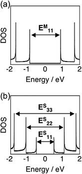 | ||
| Fig. 1 Electronic density of states (DOS) calculated in a tight binding model for (a) metallic (13,1) and (b) semiconducting (10,5) SWNTs. | ||
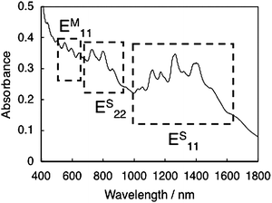 | ||
| Fig. 2 UV-vis-NIR spectrum of HiPco SWNTs dispersed in D2O with SDBS. | ||
SWNTs have extremely high molecular weight, typically up to 105–106, and tend to interact with each other by strong π–π interaction. As a result, individual SWNTs aggregate to form bundle structures, resulting in extremely poor solubility in any aqueous or organic solvents. Although fullerenes and their derivatives have been successfully incorporated into photoelectrochemical devices and cells by using various methods including spin-coating,8,9,19 Langmuir–Blodgett (LB) films,20 layer-by-layer deposition,21 and electrophoretic deposition,22 the insolubility of SWNTs has precluded the fabrication of SWNTs onto electrodes in organic solar cells. Therefore, it is necessary to solubilize SWNTs by functionalizing SWNTs covalently or noncovalently for the improvement of fabrication processability.
Recently, several approaches to the functionalization of SWNTs have been developed to overcome the solubility limitations. During the last decade, covalent attachment of functional groups to SWNTs has been widely employed to prepare exfoliated SWNTs in aqueous or organic solvents.23 For instance, carboxyl groups at the open ends and defect sites of shortened SWNTs by oxidation have frequently reacted with amines and alcohols to yield amide and ester linkages, respectively.24 The sidewalls of SWNTs are also available for covalent functionalization. Various direct addition of reactive intermediates, such as 1,3-dipolar cycloaddition of azomethine ylides,25 arylation with diazonium compounds,26 and cycloaddition of enolate anion27 to the side walls, has been reported. It must be noted, however, that the covalent functionalization significantly alters the structural and electronic properties of pristine SWNTs. Namely, peaks in the absorption spectra of the modified SWNTs due to the transitions of van Hove singularity pairs disappear after the covalent modifications.23 Supramolecular functionalization of CNTs is a potential approach to overcome this problem, because such a method does not disrupt unique electronic properties of CNTs in these composites.28Surfactants and hydrophilic polymers are known to exfoliate CNT bundles to disperse CNTs in aqueous solutions,28 but they are unsuitable for the solubilization of CNTs in organic solvents, which are more suitable for the fabrication of CNT composites into molecular devices. Utilization of π–π interaction is a promising methodology for dispersing CNTs in organic solvents as well as aqueous solvents.28d Various π electron-rich compounds including pyrene, porphyrin, and π-conjugated polymers have been employed to interact with CNTs forming supramolecular composites.28d Although the structures and electronic properties of SWNTs are preserved after the solubilization by these noncovalent interactions, a large excess of surfactants or polymers is required to achieve the solubilization as a result of the weak intermolecular interaction between the adsorbed molecules and SWNTs. Moreover, it is difficult to remove the extra solubilizers. In spite of these disadvantages, the noncovalent strategies have been employed more frequently for the fabrication of SWNT-based photoelectrochemical devices and cells than covalent methods probably due to the facile accessibility in the noncovalent treatment of SWNTs.14
3. CNTs in the active layer of photoelectrochemical devices
The utilization of CNTs in the active layer of photoelectrochemical devices is an attractive, highly potential approach in terms of several reasons. CNTs have one-dimensional structures with diameters of ∼1 nm and length on the order of micrometers (aspect ratio > 103).17 Thus, SWNT-based percolation pathways are easily formed in the films, exhibiting efficient charge separation and transport through the pathways. In fact, the extremely high surface area, ∼1600 m2 g−1, reported for purified SWNTs, offers a tremendous opportunity for exciton dissociation.29 In addition, CNTs exhibit high conductivity, which exceeds those of any conducting polymers by several orders of magnitude,30 together with strong mechanical resistance.31 These features render CNTs a candidate as the ideal charge separation and charge-transporting highway in the photoactive layer.Studies on the excited-state properties of nanocomposites of CNTs with low- or high-molecular weight compounds have provided the evidence for donor–acceptor interactions.32–35 The role of CNTs in the composites, i.e., electron donor or acceptor, depends on the redox properties of the counterpart. For example, CNTs act as electron donors when combined with fullerenes,35 and as electron acceptors in combination with porphyrins, tetrathiafulvalene (TTF) derivatives, semiconducting nanoparticles, conjugated polymers, and so on.32–34 In the devices of SWNT–FET (field-effect transistor) coated with conjugated polymers, the electronic structure of the polymers switches the function of SWNT. Namely, the SWNT acts as electron donor or acceptor, exhibiting an increase or a decrease in drain source current.36 However, the majority of these studies treats CNTs as electron acceptors. In most photoelectrochemical devices where CNTs are used in a photoactive layer, CNTs behave as electron acceptors when combined with donors.14 The general energy diagram for implementing CNTs as acceptors in photoelectrochemical devices is illustrated in Fig. 3(a). On the other hand, it is energetically possible for CNTs to act as electron donors in the photoelectrochemical devices when combined with good electron acceptors possessing high light-harvesting ability (Fig. 3(b)). The lack of such compounds may be responsible for the limitation of the photoelectrochemical devices using CNTs as electron donors.
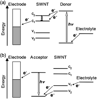 | ||
| Fig. 3 General energy diagram for using CNTs as (a) acceptors and (b) donors in photoelectrochemical devices. | ||
4. SWNT-based photoelectrochemical devices
4.1. Photoelectrochemical properties of SWNT-surfactant composite
Semiconducting SWNTs absorb visible light, which is attributed to transitions of the second and third van Hove singularity pairs, to generate electrons at the conduction band and holes at the valence band. The relaxation of the electrons and holes to the fundamental band edge occurs within 100 fs after the photoirradiation.37 Coulombic interaction between the spatially confined charges results in the formation of strongly bound excitons. If the excitons are separated with the aid of semiconducting electrodes with a suitable conduction band (CB) and a valence band (VB) before relaxation to the ground state, photocurrent generation is expected in a photoelectrochemical device with a combination of the semiconducting SWNT-semiconducting electrode in the absence of an electron donor.Recently, Kamat et al. made films from dispersion of SWNTs onto optically transparent electrodes, which are photoactive and generate photocurrent under excitation by visible light.38 To fabricate SWNTs onto an electrode, SWNTs prepared by the electric arc method (SES Research) were dispersed with irradiation of ultrasonic waves in the presence of a surfactant, tetraoctylammonium bromide (TOAB), in THF. Two indium tin oxide (ITO) electrodes, one of which is intact and the other is modified with nanostructured SnO2 colloids (denoted as ITO/SnO2), were inserted into the THF suspension and a dc voltage (<100 V) was applied. The SWNT–TOAB composites were electrophoretically deposited onto the anode ITO/SnO2 to yield visibly homogeneous and robust films. The AFM measurements revealed that SWNTs are in the form of bundles with a diameter of more than 50 nm in the deposited film.38 Photoelectrochemical measurements were carried out in a two-electrode device with the modified working electrode and a platinum gauze counter electrode and an electrolyte with 0.5 M LiI and 0.01 M I2 in acetonitrile. The maximum value of incident photon-to-photocurrent efficiency (IPCE) was very low (0.15% at 400 nm) (Table 1).38 The photoirradiation induced the cathodic flow of electrons, indicating the mechanism (Fig. 4) that the photogenerated holes are collected at the SnO2 surface and transported to the counter electrodevia an external circuit. The regenerative I3−/I−redox couple facilitates the scavenging of electrons at the electrode surfaces and thus enables the delivery of a steady photocurrent. Although the dispersant TOAB is photochemically and electrochemically inactive under the experimental conditions, the presence of TOAB may hinder efficient charge transport on the electrode.
| Electrode | PGE |
|---|---|
| a PDDA = poly(diallyl dimethylammonium) chloride; PSS = poly(sodium polystyrene-4-sulfonate); ZnP = zinc porphyrin; PSCOOH = polythiophene derivative; f-SWNT = functionalized SWNT. b IPCE values were not reported. | |
| ITO/SnO2/SWNT–TOAB | IPCE = 0.15% |
| FTO/SnO2/H2P–NT–H2P | IPCE = 4.9% |
| ITO/PDDAn+/PSSn−/(SWNT–pyrene+/ZnP8−)8 | IPCE = 8.5% |
| ITO/PDDAn+/PSSn−/(SWNT–pyrene+/PSCOOH)8 | IPCE = 9.3% |
| ITO/PDDAn+/PSSn−/SWNT–pyrene+/CdTe | IPCE = 2.3% |
| ITO/SnO2/SWNT–H4P4+ | IPCE = 13% |
| Au/SWNT/CdS | APCE = 70%b |
| FTO/SnO2/(C60 + f-SWNT)m | IPCE = 18% |
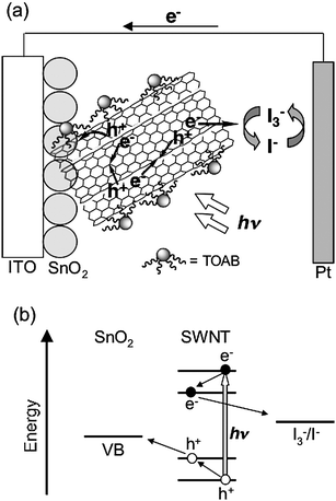 | ||
| Fig. 4 Schematic illustration for (a) photocurrent generation and (b) energy diagram in the photoelectrochemical device using the ITO/SnO2/SWNT–TOAB electrode. | ||
The photocurrent generation efficiency is poor compared to the ITO/SnO2electrode modified by C60clusters that exhibited a maximum IPCE value of 5% under similar experimental conditions.22 It should be noted here that most SWNTs exist as bundles on the semiconducting electrode, and thus the self-quenching of the excited states as well as energy transfer quenching by metallic SWNTs is facilitated by the intertube interaction. Such deactivation pathways may be responsible for the poor photocurrent generation efficiency (Fig. 4).
4.2. Relationship between bundle size and photoelectrochemical properties of SWNTs
To shed light on the relationship between the bundle formation and photoelectrochemical properties of SWNTs, we prepared SWNTs covalently functionalized with alkyl chains or bulky porphyrin units to different degrees.39 The schematic structures of the covalently modified SWNTs are displayed in Fig. 5. As expected, the solubility of SWNTs in organic solvents was improved by the attachment of bulky porphyrin units compared to that of long alkyl chains. The maximum concentration of SWNT samples after sonication for 30 min in DMF was in the order of NT-ref (0.1 g L−1) < NT–CO2H (0.15 g L−1) < NT–H2P (0.3 g L−1) < H2P–NT–H2P (0.5 g L−1). In accordance with this trend, the estimation of the bundle size by atomic force microscopy (AFM) measurements of spin-coated SWNT samples disclosed that the diameters are in the same order of NT-ref (3–12 nm) > NT–CO2H (1.5–8 nm) > NT–H2P (1–8 nm) > H2P–NT–H2P (1–3 nm) (Fig. 6). We fabricated films of the modified SWNTs on ITO/SnO2electrodes by electrophoretic deposition. The observations of the deposited films using optical microscopy and AFM showed that the film of H2P–NT–H2P has the most uniform surface morphology. In addition, the photoelectrochemical properties were evaluated using a standard three-electrode system consisting of the modified working electrode, a platinum wire counter electrode, and a Ag/AgNO3reference electrode in 0.5 M LiI and 0.01 M I2 of acetonitrile solution as the electrolyte.39 The photoelectrochemical devices revealed anodic electron flow, which is in sharp contrast with the cathodic electron flow in Kamat's device (vide supra). The maximum IPCE values at an excitation wavelength of 400 nm were as follows: FTO/SnO2/NT-ref (2.3 %) < FTO/SnO2/NT–CO2H (2.6 %) < FTO/SnO2/NT–H2P (4.0 %) < FTO/SnO2/H2P–NT–H2P (4.9 %) (Table 1). This trend for the photocurrent generation efficiency correlated well with the order of the bundle size of the SWNTs deposited on the electrode.39 The correlation suggests that the suppression of the bundle formation reduces self-quenching of the excited SWNTs as well as of energy transfer quenching by metallic SWNTs. In addition, the trend may also originate from the increased interface area for charge separation by the exfoliation of the bundle structures. These effects would lead to the remarkably improved photocurrent generation compared with Kamat's device.38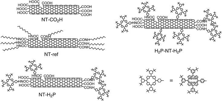 | ||
| Fig. 5 Covalently functionalized SWNTs used for the photoelectrochemical devices. | ||
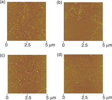 | ||
| Fig. 6 Tapping mode atomic force micrographs of (a) NT–CO2H, (b) NT-ref, (c) NT–H2P and (d) H2P–NT–H2P on mica (Z range: 50 nm). The color scale represents the height topography, with bright and dark representing the highest and lowest features, respectively. | ||
It is noteworthy that the absorption due to the porphyrin moieties does not contribute to the photocurrent generation in the two photoelectrochemical devices with the FTO/SnO2/NT–H2P and FTO/SnO2/H2P–NT–H2P electrodes with the porphyrin moieties. In other words, only direct electron injection from the excited SWNTs to the conduction band of the SnO2electrode is responsible for the photocurrent generation. This is in marked contrast with efficient quenching of the porphyrin excited singlet state by the SWNTs in NT–H2P and H2P–NT–H2P, which was observed in the steady-state fluorescence spectra.39 The photocurrent generation by the excitation of porphyrin moieties would be expected if energy transfer (EN) or electron transfer (ET) from the excited porphyrin to SWNT occurs in the present systems. Accordingly, the EN or ET quenching mechanism should be ruled out. Time-resolved transient absorption studies on a porphyrin-fullerene linked system with a short bridge disclosed an intermediate state (i.e., exciplex) prior to the following completely charge-separate state.40 The exciplex state was found to decay rapidly to the ground state rather than generate the charge-separated state. Judging from the well-established photodynamics and the similarity between fullerenes and SWNTs,40 the evolution of exciplex between the porphyrin excited singlet state and the SWNTs and the subsequent rapid decay to the ground state without generating the charge-separated state were proposed to rationalize the unusual photoelectrochemical behavior.39 Additionally, covalent attachment of the porphyrin units to the terminals, the defect sites, and the sidewalls of the SWNTs influences the electronic structures and energy levels of the SWNTs significantly. This may have a considerable impact on the photoelectrochemical performance. Exploitation of the production and separation of suitable SWNTs for efficient photocurrent generation as well as a more rational design of dye-linkage to SWNTs is necessary for the utilization of absorbed energy by the linked dye.
4.3. Photoelectrochemical devices comprised of SWNTs and electron donors
As described above, unfunctionalized SWNTs interact with π-electron rich molecules by noncovalent π–π interaction to exfoliate the bundle structure.28d Considerable efforts have been made to modify the surface of SWNTs with π-conjugated molecules such as porphyrins and π-conjugated polymers to improve the light harvesting property.28 If π-electron rich compounds are well-organized on the surface of SWNTs, electrons and holes at the interface generated by photoinduced electron transfer would be transported along the 1-D SWNTs and the array of the π-conjugated molecules efficiently, as suggested in bulk heterojunction solar cells.1,2,8–13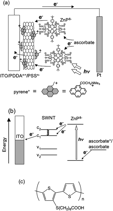 | ||
| Fig. 7 Schematic illustration for (a) photocurrent generation, (b) energy diagram of the photoelectrochemical devices using the ITO/PDDAn+/PSSn−/SWNT–pyrene+/ZnP8−electrode. (c) Molecular structure of PSCOOH. | ||
A polythiophene derivative (i.e., PSCOOH, Fig. 7(c)) and SWNT–pyrene+ were also integrated into photoactive ITO electrodes by van der Waals and electrostatic interactions.42 In the device, polythiophene can function as the light-harvesting chromophore that donates an electron to the electron-accepting SWNTs by photoinduced electron transfer. The higher maximum IPCE value of 9.3% (Table 1) than that of the ITO/PDDAn+/PSSn−/SWNT–pyrene+/ZnP8− device was achieved, which was obtained in the device with eight layers of SWNT–pyrene+/PSCOOH. In addition, Guldi et al. fabricated nanohybrid films of SWNT–pyrene+ and thioglycolic acid-capped semiconducting nanoparticles of CdTe through electrostatic interactions.43 The highest IPCE value up to 2.3% (Table 1) was noted. In this manner, layer-by-layer approaches using van der Waals and electrostatic interactions are universal and can be extended to the combinations of SWNTs with various photoactive molecules. The optimization of the molecular structure would achieve further improvement in the photocurrent generation efficiency.
Kamat et al. showed that the composite of protonated porphyrin (H4P2+) and SWNTs form rod structures by sonication that disperses well in acidified THF.44 The fully-grown SWNT–H4P2+ composite exhibited rod-like structures with a diameter of 40–60 nm and length of 0.5–3.0 μm. In the absorption spectrum of the rod-like composite, two sharp peaks (460 and 375 nm) arising from porphyrin J- and H-aggregates were observed in addition to the Soret band of monomer H4P2+ (427 nm). The authors speculated from these results that H4P2+ forms J- and H-aggregates parallel and perpendicularly to the long axis of the SWNTs, respectively (Fig. 8). Such an unusual, highly-ordered structure of the porphyrin and SWNTs is attractive as a photoactive layer of photoelectrochemical devices. With this idea in mind, the authors made thin films of the SWNT–H4P2+ composite on a nanostructured SnO2electrode by using the electrophoretic deposition method.44 The SEM measurement of the film surface showed ca. 100 nm-size clusters with irregular shapes, indicating the aggregation of the rod-like SWNT–H4P2+ composite during the deposition. The organized assemblies on the electrodes were photoactive and absorbed visible light strongly. Photocurrent measurements were performed using the ITO/SnO2/SWNT–H4P2+ as a photoanode under the standard three-electrode conditions. The maximum IPCE value reached up to 13% (Table 1) with a bias potential of 0.2 V vs. SCE, which was larger than those obtained for the individual component devices with the ITO/SnO2/SWNT and ITO/SnO2/H4P2+electrodes. The femtosecond pump–probe spectroscopy experiments disclosed the decay of the porphyrin excited singlet state in the SWNT–H4P2+assembly, suggesting electron injection from the porphyrin excited singlet state to SWNTs. These results indicated that the photoinduced charge separation in the composite molecular assemblies of SWNT–H4P2+ plays an important role in the photocurrent generation.44 In addition, other mechanisms for the photocurrent generation are plausible, since the quantum yield of the photoinduced charge separation was not estimated in this system. Thus, the energy transfer from the porphyrin excited singlet state to SWNTs in the porphyrin–SWNT composite may also be responsible for the efficient photocurrent generation, whereas direct electron injection from the porphyrin aggregates to the CB of the SnO2electrode is unlikely to occur owing to the rather large separation between the porphyrin aggregates and the SnO2electrode.
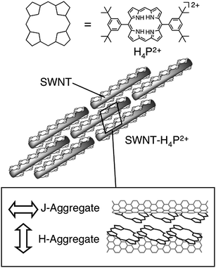 | ||
| Fig. 8 Schematic illustration for supramolecular assemblies of protonated porphyrins and SWNTs in acidified THF. | ||
Willner et al. constructed a CdS–SWNT composite on a gold electrode for photoelectrochemical devices, as shown in Fig. 9.46 First, they fabricated vertically aligned SWNTs on a gold electrode by functionalizing the electrode with a self-assembled monolayer of cysteamine (H2NCH2CH2SH) to which acid-treated, shortened SWNTs with carboxyl groups at the ends were coupled forming amide bonds.46 The AFM images of the electrode exhibited vertically standing SWNTs with maximum height of ∼20 nm. Then, the CdS semiconductor nanoparticles with an average diameter of 5 nm, which was protected by a capping monolayer of cysteamine and 2-thioethanesulfonic acid, were coupled to the other end of the SWNTs to yield Au/SWNT/CdS electrodes. The microgravimetric analyses and AFM measurements of the surface revealed a densely packed monolayer of CdS nanoparticles on the SWNT-modified electrode. The photoelectrochemical properties of the Au/SWNT/CdS, Au/SWNT, and Au/CdS electrodes were examined in the presence of triethanolamine (TEOA) as a sacrificial electron donor.46 The maximum value of absorbed photon-to-current efficiency (APCE) for the Au/SWNT/CdS device reached up to 70% (Table 1). In contrast, the maximal APCE value of the Au/CdS device was ∼1.5% and the Au/SWNT device exhibited no photocurrent under the same conditions. The action spectrum of the Au/SWNT/CdS device was consistent with the absorption spectrum of the corresponding electrode. The authors suggested that the photocurrent originates from the photoexcitation of CdS and subsequent injection of the excited electrons into the electrodevia the SWNTs (Fig. 9).46 The SWNTs that bridge the CdS particles to the electrode may facilitate the charge separation and retard the charge recombination. It should be noted here, however, that the absorbance of a monolayer is insufficient to yield a large photocurrent.5,47 Although the APCE values in the present devices are considerably high, the corresponding IPCE values would be poor as the result of poor light-harvesting properties of the monolayers on the gold electrodes.
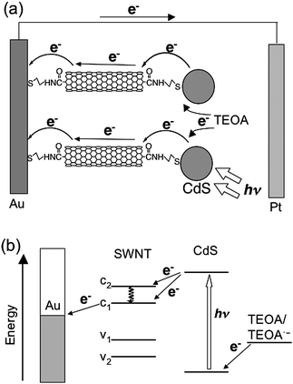 | ||
| Fig. 9 Schematic illustration for (a) photocurrent generation and (b) energy diagram in the photoelectrochemical devices using the Au/SWNT/CdS electrode. | ||
Han et al. described photoelectrochemical devices with Ru dye–viologen–SWNT composite electrodes.48 An ITO electrode was first functionalized with acid-treated SWNTs with terminal carboxylic acid by using a spray-coating method, followed by successive fabrication of di(aminopropyl)viologen (DAPV) and Ru dye (RuL2(NCS)2, L = 2,2′-bipyridine-4,4′-dicarboxylic acid) using the acid–base interactions to yield the modified ITO electrode (denoted as ITO/SWNT/DAPV/RuL2(NCS)2electrode).48 The electrode showed a photocurrent density of 10.3 nA cm−2 under air mass (AM) 1.5 conditions, which is ca. two times higher than that in the control device consisting of the ITO/DAPV/RuL2(NCS)2electrode without the SWNT layer. The authors speculated that the recombination reaction is reduced in the presence of SWNTs.48 However, the photocurrent generation efficiency is still much lower than the typical dye-sensitized solar cells using ruthenium dyes and TiO2 particles.3,4 The optimization of the molecular structure of the dyes and linkages suitable for SWNT scaffolds may improve the efficiency of the photovoltaic cells.
4.4. SWNTs as scaffolds of alignment of photoactive molecules for photoelectrochemical devices
It is known that fullerenes form clusters by the rapid injection of a poor solvent (i.e., acetonitrile) into a C60 solution in a good solvent (i.e., toluene).22 Kamat et al. applied the electrophoretic deposition technique to C60clusters [denoted as (C60)m] to obtain C60 films on electrodes.22 The modified electrodes absorbed visible light intensively. Under visible light irradiation using I−/I3− as the redox couple, the photoelectrochemical device revealed a stable photocurrent. The maximum IPCE of ∼4% was observed at the excitation wavelength of 420 nm. The IPCE value is 2–3 orders of magnitude larger than previously reported values using fullerene as photosensitizers.49Considering the remarkable optical and photoelectrochemical properties of (C60)m-modified electrodes, the arrangement of fullerene molecules along SWNTs is an attractive strategy to attain efficient transportation of charges in photoelectrochemical devices and cells. Examples of such an arrangement, however, have been limited to fullerene-encapsulated SWNTs (bucky-peapods),50,51 which are insoluble in organic solvents, making it difficult to apply them to molecular devices. Recently, we developed a novel strategy for the arrangement of C60 molecules on the external surface of SWNT.52 First, acid-treated SWNTs were functionalized with a sterically hindered amine (i.e., swallow-tailed secondary amine) to yield a highly-soluble, functionalized SWNT (denoted as f-SWNT) in organic solvents. Then, a poor solvent (i.e., acetonitrile) was rapidly injected into a mixture of C60 and f-SWNT in a good solvent (o-dichlorobenzene (ODCB)), resulting in formation of the composite clusters of C60 and f-SWNT (denoted as (C60 + f-SWNT)m). SEM measurements for cast samples revealed that the composites are categorized into three groups; (i) f-SWNT bundles covered with layers of C60 molecules (cluster I), (ii) round, large C60clusters with sizes of 500–1000 nm containing f-SWNT (cluster II), and (iii) typical, round C60clusters with moderate sizes of 150–250 nm (cluster III) (Fig. 10).52
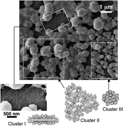 | ||
| Fig. 10 FE-SEM images of the composite clusters of f-SWNT and C60. The sample was prepared by casting the ODCB–acetonitrile (1/3 (v/v)) solution of C60 (0.14 mM) and f-SWNT (0.024 g L−1) on a glass plate. The large FE-SEM image is classified into three regions of cluster I, II, and III. The image of cluster I is also shown as an enlarged rotated picture. | ||
As in the case of (C60)m, the composite cluster (C60 + f-SWNT)m in an ODCB–acetonitrile mixture was attached to nanostructured SnO2electrodes (denoted as FTO/SnO2/(C60 + f-SWNT)m) by the electrophoretic deposition technique.52 The hierarchical film structure with gradient composition in the order of SnO2, clusters I, II, and III was achieved due to the significant difference in mobilities of the clusters during the electrophoretic deposition. The composite film exhibited IPCE values as high as 18% at 400 nm under an applied potential of 0.05 V vs. SCE. The photocurrent generation efficiency is the highest value among carbon nanotube-based photoelectrochemical devices in which carbon nanotubes are deposited electrophoretically,38,39,44 electrostatically41–43 or covalently46 onto semiconducting electrodes. The highly aligned structure of C60 molecules on the f-SWNT sidewalls may facilitate the electron flow, leading to the efficient photocurrent generation in the present system (Fig. 11). In addition to this mechanism, direct charge separation between C60 as an acceptor and f-SWNT as a donor in clusters I and II for the photocurrent generation is energetically possible. However, the preliminary transient absorption measurements using the FTO/SnO2/(C60 + f-SWNT)m electrode did not disclose the fingerprint of C60radical anion at 1000–1100 nm, indicating no occurrence of the direct charge separation between C60 and f-SWNT.52 Thus, the photocurrent generation mechanism including charge separation should be ruled out. Therefore, SWNTs do not act as an electron donor or acceptor but as a nano- and meso-scaffold of photoactive C60 molecules for the 1-D alignment, which would facilitate efficient electron transport through the 1-D fullerene arrays.
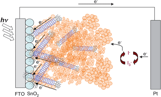 | ||
| Fig. 11 Schematic illustration for photocurrent generation in the photoelectrochemical devices using FTO/SnO2/(f-SWNT + C60)melectrode. | ||
5. SWNT-based photovoltaic cells
5.1. Incorporation of SWNTs in dye-sensitized TiO2 solar cells
The dye-sensitized solar cell (DSSC) is one of the most attractive organic solar cells because the remarkably high incident photon to current conversion efficiency can be achieved by simple and low energy consuming fabrication.3,4,53,54 In particular, porous, nanocrystalline TiO2electrodes have been used for DSSCs due to their higher cell performance than DSSCs using other metal oxide semiconducting electrodes.3,4,53,54Ruthenium(II) polypyridyl derivatives have been regarded as the best sensitizer for DSSCs because of their strong visible absorption bands, long-lived excited state, and photochemical stability.3,4,54 The highest power conversion efficiency (η) so far reported for DSSCs is ∼11% under AM1.5 (100 mW cm−2) irradiation when liquid electrolytes containing I−/I3−redox couples is used.54 Strategies to enhance the cell performance of DSSCs include efficient light-harvesting in the visible region, the promotion of electron transfer from the adsorbed dyes to the TiO2electrode and the suppression of charge recombination between the injected electrons and the dye radical cation, and efficient hole transport to the counter electrode through the liquid or solid electrolytes. In this context, significant efforts have been made to improve the cell performance by modifying TiO2electrodes using SWNTs.55–57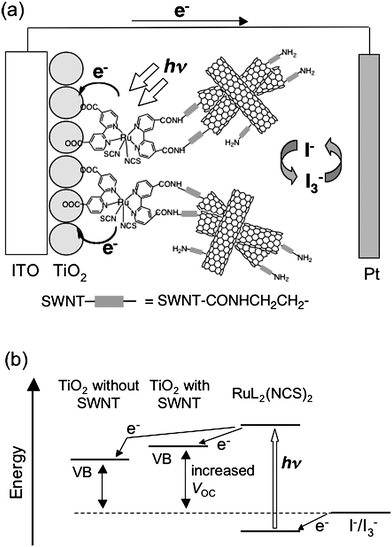 | ||
| Fig. 12 (a) Schematic illustration for photocurrent generation in the DSSC using the ITO/TiO2/RuL2(NCS)2/SWNT electrode. (b) Energy diagrams for the ITO/TiO2/RuL2(NCS)2/SWNT and ITO/TiO2/RuL2(NCS)2electrodes. | ||
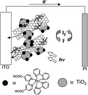 | ||
| Fig. 13 Schematic illustration for photocurrent generation in the DSSC using the ITO/SWNT–TOAB/TiO2/Ru(II) electrode. | ||
5.2. Polymer-based solar cells with CNTs
Polymeric solar cells have attracted great interest over the past 20 years.1,8,9 This technology offers various advantages including the absence of liquid electrolyte, mechanical flexibility, and ease of large-area processing. CNT materials have been typically incorporated into active layers of polymer solar cells by the dispersion of CNT in a solution of an electron-donating conjugated polymer, i.e., polythiophene (PT) or poly(p-phenylene-vinylene) (PPV) derivatives, and spin-coating the composites onto a transparent conductive electrode, typically ITO, covered with hole-blocking layer.58–62 The electrophoretic deposition method was also employed for the film fabrication.63 Finally, an aluminium layer as a cathode was thermally evaporated on the active layer. Friend et al. described the first investigation on the electronic properties of the composite of multi-walled carbon nanotubes (MWNTs) and PPV derivatives.58 On the other hand, Kymakis et al. demonstrated an increase in the cell performance by blending poly(3-octylthiophene) (P3OT) with only 1 wt% of SWNT.59 Since their pioneering work, many groups have exploited CNTs in bulk heterojunction solar cells.58–64 However, the power conversion efficiencies of polymer–CNT solar cells are as high as ca. 0.2%, which is much lower than typical values of high-performance bulk heterojunction solar cells (3–6%) with a combination with π-conjugated polymers and fullerene derivatives including PCBM ([6,6]-phenyl-C61-butyric acid methyl ester).9 The low JSC and ff are responsible for the poor cell performance.The utilization of SWNT or MWNT as a scaffold of fullerenes in conducting polymer-based solar cells was also reported.65,66 To fabricate the composite film of PT/CNT–C60, microwave irradiation64 or oxygen plasma treatment of CNTs66 was applied, respectively. The power conversion efficiencies of 0.71 and 0.11% were still much lower than the typical value (3–6%) of PT–C60 bulk heterojunction solar cells.9 The bulk heterojunction structures that consist of a three dimensional interpenetrating network of C60 on CNT and a conjugated polymer may not be fully developed within the blend films of the cells.
Recently, several groups have come up with an idea to employ SWNT and MWNT as the transparent conductive electrode,67 since high quality ITO is expensive due to the resource constraint of indium. In addition, ITO is not compatible with roll-to-roll fabrication processing in contrast with today's market requirements for a full printable solar cell. For example, Rowell et al. fabricated flexible transparent conducting electrodes by printing films of SWNT networks on a flexible poly(ethylene terephthalate) (PET) substrate and used them as transparent electrodes for poly(3-hexylthiophene) (P3HT)–PCBM bulk heterojunction solar cells.67a The power conversion efficiency was 2.5% under AM1.5 conditions, which was close to that of the ITO/glass system under their optimized conditions (3%). Further improvement of the performance may be possible through the optimization of the SWNT network structure considering the high mobility of individual SWNT.68
6. Summary
This review article focused on the utilization of CNTs, especially SWNTs, for photoelectrochemical devices and cells. Versatile methods including electrophoretic deposition, spin-coating, layer-by-layer deposition, and self-assembled monolayers were utilized for the fabrication of photoactive composite films on electrodes. However, the power conversion efficiencies are still much smaller than the values of high-performance DSSCs using mesoscopic TiO2 particles and Ru dyes (∼11%)54 and bulk heterojunction solar cells using PT or PPV derivatives and functionalized fullerene (∼5%).9 The limited cell performance results from the presence of metallic SWNTs that cause a short circuit in the device and facile deactivation in the excited state, SWNT aggregation that promotes self-quenching and energy transfer quenching of the excited states by metallic SWNTs, and contamination of impurities including metal catalyst particles and amorphous carbon.At the current stage, all SWNT production techniques inevitably lead to significant contamination of impurities and yield SWNTs with various chiral indices. To draw out the inherent properties of SWNTs, purification and sorting of SWNTs to be isolated are highly desirable. The selective solubilization using DNA,69surfactants70 and conjugated polymers71 are promising methodologies to surmount the problems. Specifically, the composite with conducting polymers can be directly applied as active layers of photoelectrochemical cells. Alternatively, the utilization of the 1-D structure of SWNTs as scaffolds for organic molecules to construct charge-transporting highways is a fascinating approach to take advantage of the unique SWNT properties. Photoactive molecule-encapsulated SWNTs,50,51 a so-called peapod structure, are also enchanting due to their potential for electron and hole-transporting through the 1-D arrays. In these cases, the versatility of SWNTs in an electronic structure would not be a problem for photoelectrochemical and photovoltaic applications.
The history of CNT-based organic solar cells is still less than 10 years old. Further extensive studies are necessary to bring out the full potential of CNTs for the realization of a further boost in the cell performance of CNT-based solar cells.
Acknowledgements
The authors are deeply indebted to the work of all collaborators and co-workers whose names are listed in the references (in particular, Prof. S. Isoda and Prof. K. Murakoshi). This work was partially supported by the World Premier International Research Center Initiative (WPI Initiative), MEXT, Japan. T. U. thanks the Shorai Foundation for Science and Technology for financial support.References
- Organic Photovoltaics, ed. S. S. Sun and R. S. Sariciftci, CRC, Boca Raton, 2005 Search PubMed.
- (a) M. Hiramoto, H. Fujiwara and M. Yokokawa, J. Appl. Phys., 1992, 72, 3781 CrossRef CAS; (b) P. Peumans, S. Uchida and R. Forrest, Nature, 2003, 425, 158 CrossRef CAS; (c) J. Xue, S. Uchida, B. P. Rand and S. R. Forrest, Appl. Phys. Lett., 2004, 84, 3013 CrossRef CAS.
- (a) B. O'Regan and M. Grätzel, Nature, 1991, 353, 737 CrossRef CAS; (b) U. Bach, D. Lupo, P. Comte, J. E. Moser, F. Weissörtel, J. Salbeck, H. Spreitzer and M. Grätzel, Nature, 1998, 395, 583 CrossRef.
- (a) A. Hagfeldt and M. Grätzel, Acc. Chem. Res., 2000, 33, 269 CrossRef CAS; (b) M. Grätzel, Nature, 2001, 414, 338 CrossRef CAS; (c) M. Grätzel, Pure Appl. Chem., 2001, 73, 459 CrossRef CAS; (d) D. F. Watsonson and G. J. Meyer, Annu. Rev. Phys. Chem., 2005, 56, 119 CrossRef CAS; (e) N. A. Anderson and T. Lian, Annu. Rev. Phys. Chem., 2005, 56, 491 CrossRef CAS; (f) N. S. Lewis, Inorg. Chem., 2005, 44, 6900 CrossRef CAS; (g) W. R. Duncan and O. V. Prezhdo, Annu. Rev. Phys. Chem., 2007, 58, 143 CrossRef CAS.
- (a) H. Imahori and Y. Sakata, Adv. Mater., 1997, 9, 537 CAS; (b) H. Imahori and Y. Sakata, Eur. J. Org. Chem., 1999, 2445 CrossRef CAS; (c) H. Imahori, Org. Biomol. Chem., 2004, 2, 1425 RSC; (d) H. Imahori, J. Phys. Chem. B, 2004, 108, 6130 CrossRef CAS; (e) H. Imahori and S. Fukuzumi, Adv. Funct. Mater., 2004, 14, 525 CrossRef CAS; (f) T. Umeyama and H. Imahori, Photosynth. Res., 2006, 87, 63 CrossRef CAS; (g) H. Imahori, Bull. Chem. Soc. Jpn., 2007, 80, 621 CrossRef CAS.
- (a) M. S. Dresselhaus, G. Dresselhaus and P. C. Eklund, Science of Fullerenes and Carbon Nanotubes, Academic Press, San Diego, 1996 Search PubMed; (b) Fullerenes, ed. K. M. Kadish and R. S. Ruoff, Wiley, New York, 2000 Search PubMed; (c) Organic Photovoltaics, ed. C. Brabec, V. Dyakonov, J. Parisi and N. S. Sariciftci, Springer, Berlin, 2003 Search PubMed.
- (a) D. M. Guldi, J. Phys. Chem. B, 2005, 109, 11432 CrossRef CAS; (b) P. V. Kamat, J. Phys. Chem. C, 2007, 111, 2834 CrossRef CAS.
- (a) N. S. Sariciftci, D. Braun, C. Zhang, V. I. Srdanov, A. J. Heeger, G. Stucky and F. Wudl, Appl. Phys. Lett., 1993, 62, 585 CrossRef CAS; (b) G. Yu, J. Gao, J. C. Hummelen, F. Wudl and A. J. Heeger, Science, 1995, 270, 1789 CrossRef CAS; (c) R. A. J. Janssen, J. C. Hummelen and N. S. Sariciftci, MRS Bull., 2005, 30, 33 CAS; (d) B. C. Thimpson and J. M. Fréchet, Angew. Chem., Int. Ed., 2008, 47, 58 CrossRef.
- (a) W. Ma, C. Yang, X. Gong, K. Lee and A. J. Heeger, Adv. Funct. Mater., 2005, 15, 1617 CrossRef CAS; (b) G. Li, V. Shrotriya, J. Huang, Y. Yao, T. Moriarty, K. Emery and Y. Yang, Nat. Mater., 2005, 4, 864 CAS; (c) Y. Kim, S. Cook, S. M. Tuladhar, S. A. Choulis, J. Nelson, J. R. Durrant, D. D. C. Bradley, M. Giles, I. Mcculloch, C.-S. Ha and M. Ree, Nat. Mater., 2006, 5, 197 CrossRef CAS; (d) H. Hoppe and N. S. Sariciftci, J. Mater. Chem., 2006, 16, 45 RSC.
- (a) T. Hasobe, Y. Kashiwagi, M. A. Absalom, J. Sly, K. Hosomizu, M. J. Crossley, H. Imahori, P. V. Kamat and S. Fukuzumi, Adv. Mater., 2004, 16, 975 CrossRef CAS; (b) T. Hasobe, P. V. Kamat, M. A. Absalom, Y. Kashiwagi, J. Sly, M. J. Crossley, K. Hosomizu, H. Imahori and S. Fukuzumi, J. Phys. Chem. B, 2004, 108, 12865 CrossRef CAS.
- T. Hasobe, P. V. Kamat, V. Troiani, N. Solladie, T. K. Ahn, S. K. Kim, D. Kim, A. Kongkanand, S. Kuwabata and S. Fukuzumi, J. Phys. Chem. B, 2005, 109, 19 CrossRef CAS.
- (a) T. Hasobe, H. Imahori, P. V. Kamat and S. Fukuzumi, J. Am. Chem. Soc., 2003, 125, 14962 CrossRef CAS; (b) T. Hasobe, S. Hattori, P. V. Kamat, Y. Urano, N. Umezawa, T. Nagano and S. Fukuzumi, Chem. Phys., 2005, 319, 243 CrossRef CAS; (c) T. Hasobe, H. Imahori, P. V. Kamat, T. K. Ahn, S. K. Kim, D. Kim, A. Fujimoto, T. Hirakawa and S. Fukuzumi, J. Am. Chem. Soc., 2005, 127, 1216 CrossRef CAS; (d) H. Imahori, A. Fujimoto, S. Kang, H. Hotta, K. Yoshida, T. Umeyama, Y. Matano, S. Isoda, M. Isosomppi, N. V. Tkachenko and H. Lemmetyinen, Chem.–Eur. J., 2005, 11, 7265 CrossRef CAS; (e) H. Imahori, K. Mitamura, Y. Shibano, T. Umeyama, Y. Matano, K. Yoshida, S. Isoda, Y. Araki and O. Ito, J. Phys. Chem. B, 2006, 110, 11399 CrossRef CAS.
- (a) S. Kang, T. Umeyama, M. Ueda, Y. Matano, H. Hotta, K. Yoshida, S. Isoda, M. Shiro and H. Imahori, Adv. Mater., 2006, 18, 2549 CrossRef CAS; (b) H. Imahori, M. Ueda, S. Kang, H. Hayashi, S. Hayashi, H. Kaji, S. Seki, A. Saeki, S. Tagawa, T. Umeyama, Y. Matano, K. Yoshida, S. Isoda, M. Shiro, N. V. Tkachenko and H. Lemmetyinen, Chem.–Eur. J., 2007, 13, 10182 CrossRef CAS.
- (a) R. A. Hatton, A. J. Miller and S. R. P. Silva, J. Mater. Chem., 2008, 18, 1183 RSC; (b) V. Sgobba and D. M. Guldi, J. Mater. Chem., 2008, 18, 153 RSC.
- (a) M. Law, L. E. Greene, J. C. Johnson, R. Saykally and P. Yang, Nat. Mater., 2005, 4, 455 CrossRef CAS; (b) L. E. Greene, M. Law, B. D. Yuhas and P. Yang, J. Phys. Chem. C, 2007, 111, 18451 CrossRef CAS; (c) J. R. Maiolo III, B. M. Kayes, M. A. Filler, M. C. Putnam, M. D. Kelzenberg, H. A. Atwater and N. S. Lewis, J. Am. Chem. Soc., 2007, 129, 12346 CrossRef; (d) K. S. Leschkies, R. Divakar, J. Basu, E. Enache-Pommer, J. E. Boercker, C. B. Carter, U. R. Kortshagen, D. J. Norris and E. S. Aydil, Nano Lett., 2007, 7, 1793 CrossRef CAS; (e) E. Enache-Pommer, J. E. Boercker and E. S. Aydil, Appl. Phys. Lett., 2007, 91, 123116 CrossRef.
- Industrial grade SWNT (60 wt%) is $40 g−1 at Cheap Tubes, Inc. Home Page: http://www.cheaptubesinc.com/highpurityold.htm (accessed 23/03/08).
- R. Saito, G. Dresselhaus and M. S. Dresselhaus, Physical Properties of Carbon Nanotubes, Silverstein, Imperial College Press, London, 1998 Search PubMed.
- (a) T. W. Odom, J.-L. Huang, P. Kim and C. M. Lieber, J. Phys. Chem. B, 2000, 104, 2794 CrossRef CAS; (b) S. Niyogi, M. A. Hamon, H. Hu, B. Zhao, P. Bhowmik, R. Sen, M. E. Itkis and R. C. Haddon, Acc. Chem. Res., 2002, 35, 1105 CrossRef CAS.
- (a) H. Imahori, J.-C. Liu, K. Hosomizu, T. Sato, Y. Mori, H. Hotta, Y. Matano, Y. Araki, O. Ito, N. Maruyama and S. Fujita, Chem. Commun., 2004, 2066 RSC; (b) H. Imahori, J.-C. Liu, H. Hotta, A. Kira, T. Umeyama, Y. Matano, G. Li, S. Ye, M. Isosomppi, N. V. Tkachenko and H. Lemmetyinen, J. Phys. Chem. B, 2005, 109, 18465 CrossRef CAS; (c) A. Kira, M. Tanaka, T. Umeyama, Y. Matano, N. Yoshimoto, Y. Zhang, S. Ye, H. Lehtivuori, N. V. Tkachenko, H. Lemmetyinen and H. Imahori, J. Phys. Chem. C, 2007, 111, 13618 CrossRef CAS.
- (a) D. Zhou, L. Gan, C. Luo, H. Tan, C. Huang, G. Yao, X. Zhao, Z. Liu, X. Xia and B. Zhang, J. Phys. Chem., 1996, 100, 3150 CrossRef CAS; (b) J. Jin, L. S. Li, Y. Li, Y. J. Zhang, X. Chen, D. Wang, S. Jiang and T. J. Li, Langmuir, 1999, 15, 4565 CrossRef CAS; (c) N. V. Tkachenko, E. Vuorimaa, T. Kesti, A. S. Alekseev, A. Y. Tauber, P. H. Hynninen and H. Lemmetyinen, J. Phys. Chem. B, 2000, 104, 6371 CrossRef CAS; (d) N. V. Tkachenko, V. Vehmanen, J.-P. Nikkanen, H. Yamada, H. Imahori, S. Fukuzumi and H. Lemmetyinen, Chem. Phys. Lett., 2002, 366, 245 CrossRef CAS.
- (a) M. Lahav, V. Heleg-Shabtai, J. Wasserman, E. Katz, I. Willner, H. Durr, Y.-Z. Hu and S. H. Bossmann, J. Am. Chem. Soc., 2000, 122, 11480 CrossRef CAS; (b) C. Luo, D. M. Guldi, M. Maggini, E. Menna, S. Mondini, N. A. Kotov and M. Prato, Angew. Chem., Int. Ed., 2000, 39, 3905 CrossRef CAS; (c) F. B. Abdelrazzaq, R. C. Kwong and M. E. Thompson, J. Am. Chem. Soc., 2002, 124, 4796 CrossRef CAS; (d) D. M. Guldi, I. Zilbermann, G. A. Anderson, K. Kordatos, M. Prato, R. Tafuro and L. Valli, J. Mater. Chem., 2004, 14, 303 RSC.
- (a) P. V. Kamat, S. Barazzouk, K. G. Thomas and S. Hotchandani, J. Phys. Chem. B, 2000, 104, 4014 CrossRef CAS; (b) S. Barazzouk, S. Hotchandani and P. V. Kamat, Adv. Mater., 2001, 13, 1614 CrossRef; (c) H. Imahori, J. Mater. Chem., 2007, 17, 31 RSC.
- (a) Y.-P. Sun, K. Fu, Y. Lin and W. Huang, Acc. Chem. Res., 2002, 35, 1096 CrossRef CAS; (b) C. A. Dyke and J. M. Tour, J. Phys. Chem. A, 2004, 108, 11151 CrossRef CAS; (c) C. A. Dyke and J. M. Tour, Chem.–Eur. J., 2004, 10, 812 CrossRef CAS; (d) S. B. Banerjee, T. Hemraj-Benny and S. S. Wong, Adv. Mater., 2005, 17, 17 CrossRef CAS; (e) D. Tasis, N. Tagmatarchis, A. Blamco and M. Prato, Chem. Rev., 2006, 106, 1105 CrossRef CAS.
- (a) J. Chen, M. A. Hamon, H. Hu, Y. Chen, M. A. Rao, P. C. Eklund and R. C. Haddon, Science, 1998, 282, 95 CrossRef CAS; (b) J. E. Riggs, Z. Guo, D. L. Carroll and Y.-P. Sun, J. Am. Chem. Soc., 2000, 122, 5879 CrossRef CAS; (c) Y.-P. Sun, W. Huang, Y. Lin, K. Fu, A. Kitaygorodskiy, L. A. Riddle, Y. J. Yu and D. L. Carroll, Chem. Mater., 2001, 13, 2864 CrossRef CAS; (d) H. Hu, B. Zhao, M. A. Hamon, K. Kamaras, M. E. Itkis and R. C. Haddon, J. Am. Chem. Soc., 2003, 125, 14893 CrossRef CAS.
- (a) V. Georgakilas, K. Kordatos, M. Prato, D. M. Guldi, M. Holzinger and A. Hirsch, J. Am. Chem. Soc., 2002, 124, 760 CrossRef CAS; (b) V. Georgakilas, D. Voulgaris, E. Vazquez, M. Prato, D. M. Guldi, A. Kukovecz and H. Kuzmany, J. Am. Chem. Soc., 2002, 124, 14318 CrossRef CAS; (c) N. Tagmatarchis and M. Prato, J. Mater. Chem., 2004, 14, 437 RSC.
- (a) J. L. Bahr, J. Yang, D. V. Kosynkin, M. J. Bronikowski, R. E. Smalley and J. M. Tour, J. Am. Chem. Soc., 2001, 123, 6536 CrossRef CAS; (b) J. L. Bah and J. M. Tour, Chem. Mater., 2001, 13, 3823 CrossRef CAS; (c) J. L. Bah and J. M. Tour, J. Mater. Chem., 2002, 12, 1952 RSC; (d) M. S. Strano, C. A. Dyke, M. L. Usrey, P. W. Barone, M. J. Allen, H. Shan, C. Kittrell, R. H. Hauge, J. M. Tour and R. E. Smalley, Science, 2003, 301, 1519 CrossRef CAS.
- (a) K. S. Coleman, S. R. Bailey, S. Fogden and M. L. H. Green, J. Am. Chem. Soc., 2003, 125, 8722 CrossRef CAS; (b) K. A. Worsley, K. R. Moonoosawmy and P. Kruse, Nano Lett., 2004, 4, 1541 CrossRef CAS; (c) T. Umeyama, N. Tezuka, M. Fujita, Y. Matano, N. Takeda, K. Murakoshi, K. Yoshida, S. Isoda and H. Imahori, J. Phys. Chem. C, 2007, 111, 9734 CrossRef CAS.
- (a) E. Katz and I. Willner, ChemPhysChem, 2004, 5, 1084 CrossRef CAS; (b) P. Liu, Eur. Polym. J., 2005, 41, 2693 CrossRef CAS; (c) Y. Lin, S. Taylor, H. Li, K. A. S. Fernando, L. Qu, W. Wang, L. Gu, B. Zhou and Y.-P. Sun, J. Mater. Chem., 2004, 14, 527 RSC; (d) H. Murakami and N. Nakashima, J. Nanosci. Nanotechnol., 2006, 6, 16 CAS.
- M. Cinke, J. Li, B. Chen, A. Cassell, L. Delzeit, J. Han and M. Meyyappan, Chem. Phys. Lett., 2002, 365, 69 CrossRef CAS.
- (a) T. W. Ebbesen, H. J. Lezec, H. Hiura, J. W. Bennett, H. F. Ghaemi and T. Thio, Nature, 1996, 382, 54 CrossRef CAS; (b) R. H. Baughman, A. A. Zakhidov and W. A. de Heer, Science, 2002, 297, 787 CrossRef CAS.
- L. S. Schadler, S. C. Giannaris and P. M. Ajayan, Appl. Phys. Lett., 1998, 73, 3842 CrossRef CAS.
- (a) R. Chitta and F. D'Souza, J. Mater. Chem., 2008, 18, 1440 RSC; (b) S. Campidelli, C. Klumpp, A. Bianco, D. M. Guldi and M. Prato, J. Phys. Org. Chem., 2006, 19, 531 CrossRef CAS; (c) D. M. Guldi, G. M. A. Rahman, F. Zerbetto and M. Prato, Acc. Chem. Res., 2005, 38, 871 CrossRef CAS.
- (a) H. Li, R. B. Martin, B. A. Harruff, R. A. Carino, L. F. Allard and Y.-P. Sun, Adv. Mater., 2004, 16, 896 CrossRef CAS; (b) D. Baskaran, J. W. Mays, X. P. Zhang and M. S. Bratcher, J. Am. Chem. Soc., 2005, 127, 6916 CrossRef CAS; (c) D. M. Guldi, H. Taieb, G. M. A. Rahman, N. Tagmatarchis and M. Prato, Adv. Mater., 2005, 17, 871 CrossRef CAS; (d) D. M. Guldi, G. M. A. Rahman, J. Ramey, M. Marcaccio, D. Paolucci, F. Paolucci, S. Qin, W. T. Ford, D. Balbinot, N. Jux, N. Tagmatarchis and M. Prato, Chem. Commun., 2004, 2034 RSC; (e) K. Saito, V. Troiani, H. Qin, N. Solladie, T. Sakata, H. Mori, M. Ohama and S. Fukuzumi, J. Phys. Chem. C, 2007, 111, 1194 CrossRef CAS.
- (a) I. Robel, B. A. Bunker and P. V. Kamat, Adv. Mater., 2005, 17, 2458 CrossRef CAS; (b) M. A. Herranz, C. Ehli, S. Campidelli, M. Gutierrez, G. L. Hug, K. Ohkubo, S. Fukuzumi, M. Prato, N. Martin and D. M. Guld, J. Am. Chem. Soc., 2008, 130, 66 CrossRef; (c) B. Ballesteros, G. de la Torre, C. Ehli, G. M. A. Rahman, F. Agulló-Rueda, D. M. Guldi and T. Torres, J. Am. Chem. Soc., 2007, 129, 5061 CrossRef CAS; (d) H. Ago, M. S. Shaffer, D. S. Ginger, A. H. Windle and R. H. Friend, Phys. Rev. B, 2000, 61, 2286 CrossRef CAS.
- (a) F. D'Souza, R. Chitta, A. S. D. Sandanayaka, N. K. Subbaiyan, L. D'Souza, Y. Araki and O. Ito, J. Am. Chem. Soc., 2007, 129, 15865 CrossRef CAS; (b) D. S. Hecht, R. J. A. Ramirez, M. Briman, E. Artukovic, K. S. Chichak, J. F. Stoddart and G. Gruner, Nano Lett., 2006, 6, 2031 CrossRef CAS; (c) P. J. Boul, D.-G. Cho, G. M. A. Rahman, M. Marquez, Z. Ou, K. M. Kadish, D. M. Guldi and J. L. Sessler, J. Am. Chem. Soc., 2007, 129, 5683 CrossRef CAS.
- (a) J. S. Chawla, D. Gupta and K. S. Narayan, Appl. Phys. Lett., 2007, 91, 043510 CrossRef; (b) Y. Shi, H. Tantang, C. W. Lee, C.-H. Weng, X. Dong, L.-J. Li and P. Chen, Appl. Phys. Lett., 2008, 92, 103310 CrossRef.
- Y. Z. Ma, J. Zimmermann, S. M. Bachilio, R. E. Smalley, R. B. Weisman and G. R. Flemming, J. Chem. Phys., 2004, 120, 3368 CrossRef CAS.
- S. Barazzouk, S. Hotchandani, K. Vinodgopal and P. V. Kamat, J. Phys. Chem. C, 2004, 108, 17015 Search PubMed.
- T. Umeyama, M. Fujita, N. Tezuka, N. Kadota, Y. Matano, K. Yoshida, S. Isoda and H. Imahori, J. Phys. Chem. C, 2007, 111, 11484 CrossRef CAS.
- (a) N. V. Tkachenko, L. Rantala, A. Y. Tauber, J. Helaja, P. H. Hynninen and H. Lemmetyinen, J. Am. Chem. Soc., 1999, 121, 9378 CrossRef CAS; (b) T. J. Kesti, N. V. Tkachenko, V. Vehmanen, H. Yamada, H. Imahori, S. Fukuzumi and H. Lemmetyinen, J. Am. Chem. Soc., 2002, 124, 8067 CrossRef CAS; (c) N. V. Tkachenko, H. Lemmetyinen, J. Sonoda, K. Ohkubo, T. Sato, H. Imahori and S. Fukuzumi, J. Phys. Chem. A, 2003, 107, 8834 CrossRef CAS.
- (a) D. M. Guldi, G. M. A. Rahman, M. Prato, N. Jux, S. Qin and W. Ford, Angew. Chem., Int. Ed., 2005, 44, 2015 CrossRef CAS; (b) V. Sgobba, G. M. A. Rahaman, D. M. Guldi, N. Jux, S. Campidelli and M. Prato, Adv. Mater., 2006, 18, 2264 CrossRef.
- G. M. A. Rahaman, D. M. Guldi, R. Cagnoli, A. Mucci, L. Schenetti, L. Vaccari and M. Prato, J. Am. Chem. Soc., 2005, 127, 10051 CrossRef CAS.
- D. M. Guldi, G. M. A. Rahman, V. Sgobba, N. A. Kotov, D. Bonifazi and M. Prato, J. Am. Chem. Soc., 2006, 128, 2315 CrossRef CAS.
- (a) T. Hasobe, S. Fukuzumi and P. V. Kamat, J. Am. Chem. Soc., 2005, 127, 11884 CrossRef CAS; (b) T. Hasobe, S. Fukuzumi and P. V. Kamat, J. Phys. Chem. B, 2006, 110, 25477 CrossRef CAS.
- (a) P. Diao, Z. Liu, B. Wu, X. L. Nan, J. Zhang and Z. Wei, ChemPhysChem, 2002, 3, 898 CrossRef CAS; (b) Z. Liu, Z. Shen, T. Zhu, S. Hou, L. Ying, Z. Shi and Z. Gu, Langmuir, 2000, 16, 3569 CrossRef CAS; (c) J. J. Gooding, R. Wibowo, J. Liu, W. Yang, D. Losic, S. Orbons, F. J. Mearns, J. G. Shapter and D. B. Hibbert, J. Am. Chem. Soc., 2003, 125, 9006 CrossRef CAS.
- L. Sheeney-Haj-Ichia, B. Basnar and I. Willner, Angew. Chem., Int. Ed., 2005, 44, 78 CrossRef.
- (a) T. Akiyama, H. Imahori, A. Ajavakom and Y. Sakata, Chem. Lett., 1996, 907 CAS; (b) H. Imahori, S. Ozawa, K. Ushida, M. Takahashi, T. Azuma, A. Ajavakom, T. Akiyama, M. Hasegawa, S. Taniguchi, T. Okada and Y. Sakata, Bull. Chem. Soc. Jpn., 1999, 72, 485 CrossRef CAS; (c) H. Yamada, H. Imahori and S. Fukuzumi, J. Mater. Chem., 2002, 12, 2034 RSC; (d) H. Imahori, H. Norieda, H. Yamada, Y. Nishimura, I. Yamazaki, Y. Sakata and S. Fukuzumi, J. Am. Chem. Soc., 2001, 123, 100 CrossRef CAS.
- W. Lee, J. Lee, S.-H. Lee, J. Chang, W. Yi and S.-H. Han, J. Phys. Chem. C, 2007, 111, 9110 CrossRef CAS.
- (a) C. Luo, C. Huang, L. Gan, D. Zhou, W. Xia, Q. Zhuang, Y. Zhao and Y. Huang, J. Phys. Chem., 1996, 100, 16685 CrossRef CAS; (b) W. Zhang, Y. Shi, L. Gan, C. Huang, H. Luo, D. Wu and N. Li, J. Phys. Chem. B, 1999, 103, 675 CrossRef CAS; (c) H. Imahori, T. Azuma, S. Ozawa, H. Yamada, K. Ushida, A. Ajavakom, H. Norieda and Y. Sakata, Chem. Commun., 1999, 557 RSC; (d) H. Imahori, T. Azuma, A. Ajavakom, H. Norieda, H. Yamada and Y. Sakata, J. Phys. Chem. B, 1999, 103, 7233 CrossRef CAS.
- (a) B. W. Smith, M. Monthioux and D. E. Luzzi, Nature, 1998, 396, 323 CrossRef CAS; (b) H. Kataura, Y. Maniwa, M. Abe, A. Fujiwara, T. Kodama, K. Kikuchi, H. Imahori, Y. Misaki, S. Suzuki and Y. Achiba, Appl. Phys. A, 2002, 74, 349 CrossRef CAS; (c) D. A. Britz, A. N. Khlobystov, J. Wang, A. S. O'Neil, M. Poliakoff, A. Ardavan and G. A. D. Briggs, Chem. Commun., 2004, 176 RSC; (d) A. N. Khlobystov, D. A. Britz and G. A. D. Briggs, Acc. Chem. Res., 2005, 38, 901 CrossRef CAS.
- (a) Y. Takaguchi, M. Tamura, Y. Sako, Y. Yanagimoto, S. Tsuboi, T. Uchida, K. Shimamura, S. Kimura, T. Wakahara, Y. Maeda and T. Akasaka, Chem. Lett., 2005, 34, 1608 CrossRef CAS; (b) D. M. Guldi, E. Menna, M. Maggini, M. Marcaccio, D. Paolucci, F. Paolucci, S. Campidelli, M. Prato, G. M. A. Rahman and S. Schergna, Chem.–Eur. J., 2006, 12, 3975 CrossRef CAS; (c) A. G. Nasibulin, P. V. Pikhitsa, H. Jiang, D. P. Brown, A. V. Krasheninnikov, A. S. Anisimov, P. Queipo, A. Moisala, D. Gonzalez, G. Lientschnig, A. Hassanien, S. D. Shandakov, G. Lolli, D. E. Resasco, M. Choi, D. Tománek and E. I. Kauppinen, Nat. Nanotech., 2007, 2, 156 Search PubMed; (d) J. L. Delgado, P. Cruz, A. Urbina, J. T. L. Navarrete, J. Casado and F. Langa, Carbon, 2007, 45, 2250 CrossRef CAS.
- T. Umeyama, N. Tezuka, M. Fujita, S. Hayashi, N. Kadota, Y. Matano and H. Imahori, Chem.–Eur. J., 2008, 14, 4875 CrossRef.
- (a) S. Eu, H. Hayashi, T. Umeyama, Y. Matano, Y. Araki and H. Imahori, J. Phys. Chem. C, 2008, 112, 4396 CrossRef CAS; (b) M. Tanaka, S. Hayashi, S. Eu, T. Umeyama, Y. Matano and H. Imahori, Chem. Commun., 2007, 2069 RSC; (c) Y. Shibano, T. Umeyama, Y. Matano and H. Imahori, Org. Lett., 2007, 9, 1971 CrossRef CAS; (d) S. Eu, S. Hayashi, T. Umeyama, A. Oguro, M. Kawasaki, N. Kadota, Y. Matano and H. Imahori, J. Phys. Chem. C, 2007, 111, 3528 CrossRef CAS; (e) H. Imahori, S. Hayashi, T. Umeyama, S. Eu, A. Oguro, S. Kang, Y. Matano, T. Shishido, S. Ngamsinlapasathian and S. Yoshikawa, Langmuir, 2006, 22, 11405 CrossRef CAS.
- (a) M. K. Nazeeruddin, F. D. Angelis, S. Fantacci, A. Selloni, G. Viscardi, P. Liska, S. Ito, B. Takeru and M. Grätzel, J. Am. Chem. Soc., 2005, 127, 16835 CrossRef CAS; (b) Z.-S. Wang, H. Kawauchi, T. Kashima and H. Arakawa, Coord. Chem. Rev., 2004, 248, 1381 CrossRef CAS; (c) C.-Y. Chen, S.-J. Wu, C.-G. Wu, J.-G. Chen and K.-C. Ho, Angew. Chem., Int. Ed., 2006, 45, 5822 CrossRef CAS; (d) K.-J. Jiang, N. Masaki, J.-B. Xia, S. Noda and S. Yanagida, Chem. Commun., 2006, 2460 RSC; (e) M. Adachi, Y. Murata, J. Takao, J. Jiu, M. Sakamoto and F. Wang, J. Am. Chem. Soc., 2004, 126, 14943 CrossRef CAS; (f) Y. Chiba, A. Islam, R. Komiya, N. Koide and L. Han, Appl. Phys. Lett., 2006, 88, 223505 CrossRef.
- (a) S.-R. Jang, R. Vittal and K.-J. Kim, Langmuir, 2004, 20, 9807 CrossRef CAS; (b) K.-H. Jung, S.-R. Jang, R. Vittal, D. Kim and K.-J. Kim, Bull. Korean Chem. Soc., 2003, 24, 1501 CAS; (c) K.-H. Jung, J. S. Hong, R. Vittal and K.-J. Kim, Chem. Lett., 2002, 864 CrossRef CAS.
- (a) P. Brown, K. Takechi and P. V. Kamat, J. Phys. Chem. C, 2008, 112, 4776 CrossRef CAS; (b) A. Kongknand, R. M. Domínguez and P. V. Kamat, Nano Lett., 2007, 7, 676 CrossRef CAS; (c) F. Vietmeyer, B. Seger and P. V. Kamat, Adv. Mater., 2007, 19, 2935 CrossRef CAS; (d) I. Robel, B. A. Bunker and P. V. Kamat, Adv. Mater., 2005, 17, 2458 CrossRef CAS.
- (a) N. Ikeda and T. Miyasaka, Chem. Lett., 2007, 36, 466 CrossRef CAS; (b) T. Y. Lee, P. S. Alegaonkar and J.-B. Yoo, Thin Solid Films, 2007, 515, 5131 CrossRef CAS.
- H. Ago, K. Petritsch, M. S. P. Shaffer, A. H. Windle and R. H. Friend, Adv. Mater., 1999, 11, 1281 CrossRef CAS.
- (a) E. Kymakis, E. Stratakis and E. Koudoumas, Thin Solid Films, 2007, 515, 8598 CrossRef CAS; (b) E. Kymakis, P. Servati, P. Tzanetakis, N. Kornilios, I. Rompogiannakis, Y. Franghiadakis and G. A. J. Amaratunga, Nanotechnology, 2007, 18, 435702 CrossRef; (c) E. Kymakis, E. Koudoumas, I. Franghiadakis and G. A. J. Amaratunga, J. Phys. D: Appl. Phys., 2006, 39, 1058 CrossRef CAS; (d) S. Bhattachayya, E. Kymakis and G. A. J. Amaratunga, Chem. Mater., 2004, 16, 4819 CrossRef; (e) E. Kymakis and G. A. J. Amaratunga, Sol. Energy Mater. Sol. Cells, 2003, 80, 465 CrossRef CAS; (f) E. Kymakis, I. Alexandrou and G. A. J. Amaratunga, J. Appl. Phys., 2003, 93, 1764 CrossRef CAS; (g) E. Kymakis and G. A. J. Amaratunga, Appl. Phys. Lett., 2002, 80, 112 CrossRef CAS.
- (a) S. Berson, R. Bettingbies, S. Bailly, S. Guillerez and B. Jousselme, Adv. Funct. Mater., 2007, 17, 3363 CrossRef CAS; (b) J. Geng and T. Zeng, J. Am. Chem. Soc., 2006, 128, 16827 CrossRef CAS; (c) B. J. Landi, R. P. Raffaelle, S. L. Castro and S. G. Bailey, Prog. Photovoltaics, 2005, 13, 165 CAS.
- (a) A. F. Nogueira, B. S. Lomba, M. A. Soto-Ovideo, C. R. D. Correia, P. Corio, C. A. Furtado and I. A. Hümmelegen, J. Phys. Chem. C, 2007, 111, 18431 CrossRef CAS; (b) R. L. Patyk, B. S. Lomba, A. F. Nogueira, C. A. Furtado, A. P. Santos, R. M. Q. Mello, L. Micaroni and I. A. Hümmelegen, Phys. Status Solidi (RRL), 2007, 1, R43 Search PubMed.
- S. Kazaoui, N. Minami, B. Nalini, Y. Kim and K. Hara, J. Appl. Phys., 2005, 98, 084314 CrossRef.
- F. Itoh, I. Suzuki and K. Miyairi, Jpn. J. Appl. Chem., 2005, 44, 636 Search PubMed.
- S. Chaudhary, H. Lu, A. M. Müller, C. J. Bardeen and M. Ozkan, Nano Lett., 2007, 7, 1973 CrossRef CAS.
- C. Li, Y. Chen, Y. Wang, Z. Iqbal, M. Chhowalla and S. Mitra, J. Mater. Chem., 2007, 17, 2406 RSC; (a) C. Li and S. Mitra, Appl. Phys. Lett., 2007, 91, 253112 CrossRef.
- G. Kalita, S. Adhikari, H. Ram Aryal, M. Umeno, R. Afre, T. Soga and M. Sharon, Appl. Phys. Lett., 2008, 92, 063508 CrossRef.
- (a) M. W. Rowell, M. A. Topinka, M. D. McGehee, H. J. Prall, G. Dennler, N. S. Sariciftci, L. B. Hu and G. Gruner, Appl. Phys. Lett., 2006, 88, 233506 CrossRef; (b) J. van de Lagemaat, T. M. Barnes, G. Rumbles, S. E. Shaheen, T. J. Coutts, C. Weeks, I. Levitsky, J. Peltola and P. Glatkowski, Appl. Phys. Lett., 2006, 88, 233503 CrossRef; (c) R. Ulbricht, S. B. Lee, X. Jiang, K. Inoue, M. Zhang, S. Fang, R. H. Baughman and A. A. Zakhidov, Sol. Energy Mater. Sol. Cells, 2007, 91, 416 CrossRef CAS; (d) E. Kymakis, G. Klapsis, E. Koudoumas, E. Stratakis, N. Kornilios, N. Vidakis and Y. Franghiadakis, Eur. Phys. J.: Appl. Phys., 2006, 36, 257 CrossRef CAS; (e) A. D. Pasquier, H. E. Unalan, A. Kanwal, S. Miller and M. Chhowalla, Appl. Phys. Lett., 2006, 87, 203511; (f) E. Kymakis, E. Stratakis and E. Koudoumas, Thin Solid Films, 2007, 515, 8598 CrossRef CAS.
- T. Durkop, S. A. Getty, Enrique Cobas and M. S. Fuhrer, Nano Lett., 2004, 4, 35 CrossRef.
- (a) M. Zheng, A. Jagota, M. S. Strano, A. P. Santos, P. Barone, S. G. Chou, B. A. Diner, M. S. Dresselhaus, R. S. Mclean, G. B. Onoa, G. G. Samsonidze, E. D. Semke, M. Usrey and D. J. Walls, Science, 2003, 302, 1545 CrossRef CAS; (b) M. Zheng, A. Jagota, E. D. Semke, B. A. Diner, R. S. Mclean, S. R. Lustig, R. E. Richardson and N. G. Tassi, Nat. Mater., 2003, 2, 338 CrossRef CAS.
- M. S. Arnold, A. A. Green, J. F. Hulvat, S. I. Stuoo and M. C. Hersam, Nat. Nanotech., 2006, 1, 63 Search PubMed.
- (a) T. Umeyama, N. Kadota, N. Tezuka, Y. Matano and H. Imahori, Chem. Phys. Lett., 2007, 444, 263 CrossRef CAS; (b) A. Nish, J.-Y. Hwang, J. Doig and R. J. Nicholas, Nat. Nanotech., 2007, 2, 640 Search PubMed; (c) F. Chen, B. Wang, Y. Chen and L.-J. Li, Nano Lett., 2007, 7, 3013 CrossRef CAS; (d) A. Nish, J.-Y. Hwang, J. Doig and R. J. Nicholas, Nanotechnology, 2008, 19, 095603 CrossRef.
| This journal is © The Royal Society of Chemistry 2008 |
