Hydrogen spillover in the context of hydrogen storage using solid-state materials
Hansong
Cheng
a,
Liang
Chen
b,
Alan C.
Cooper
a,
Xianwei
Sha
a and
Guido P.
Pez
a
aAir Products and Chemicals, Inc., 7201 Hamilton Boulevard, Allentown, PA 18195-1501, USA
bNingbo Institute of Materials Technology and Engineering, Chinese Academy of Science, Ningbo, Zhejiang, 315201, PR China
First published on 3rd July 2008
Abstract
Hydrogen spillover has emerged as a possible technique for achieving high-density hydrogen storage at near-ambient conditions in lightweight, solid-state materials. We present a brief review of our combined theoretical and experimental studies on hydrogen spillover mechanisms in solid-state materials where, for the first time, the complete mechanisms that dictate hydrogen spillover processes in transition metal oxides and nanostructured graphitic carbon-based materials have been revealed. The spillover process is broken into three primary steps: (1) dissociative chemisorption of gaseous H2 on a transition metal catalyst; (2) migration of H atoms from the catalyst to the substrate and (3) diffusion of H atoms on substrate surfaces and/or in the bulk materials. In our theoretical studies, the platinum catalyst is modeled with a small Pt cluster and the catalytic activity of the cluster is examined at full H atom saturation to account for the essentially constant, high H2 pressures used in experimental studies of hydrogen spillover. Subsequently, the energetic profiles associated with H atom migrations from the catalyst to the substrates and H atom diffusion in the substrates are mapped out by calculating the minimum energy pathways. It is observed that the spillover mechanisms for the transition metal oxides and graphitic carbon-based materials are very different. Hydrogen spillover in the transition metal oxides is moderated by massive, nascent hydrogen bonding networks in the crystalline lattice, while H atom diffusion on the nanostructured graphitic carbon materials is governed mostly by physisorption of H atoms. The effects of carbon material surface curvature on the hydrogen spillover as well as on hydrogen desorption dynamics are also discussed. The proposed hydrogen spillover mechanism in carbon-based materials is consistent with our experimental observations of the solid-state catalytic hydrogenation/dehydrogenation of coronene.
 Hansong Cheng Hansong Cheng | Hansong Cheng received his PhD in theoretical chemistry from Princeton University in 1991 and subsequently joined Air Products and Chemicals, Inc. as a computational chemist. He has developed and applied efficient computational methods for design and development of novel materials for a wide variety of applications such as hydrogen storage and semiconductors. He has authored 97 publications, delivered over 65 invited lectures worldwide at professional conferences and academic, government and industrial labs, and is an inventor of over 12 US patents and patent applications. |
Liang Chen received his BS in Applied Chemistry from Nanjing University, PR China in 2001. He obtained his PhD from the Department of Chemical Engineering at the University of Pittsburgh in 2006. He then spent one year as a Postdoctoral Fellow at Air Products and Chemicals, Inc. working on a hydrogen storage project supported by the US Department of Energy Hydrogen Sorption Center of Excellence. He joined the Ningbo Institute of Materials Technology and Engineering, Chinese Academy of Sciences as an associate professor in 2007. One of his primary research interests is to use computer modeling for design of new catalysts and novel hydrogen storage materials. |
Alan C. Cooper received his PhD in Inorganic Chemistry from Indiana University in 1997. After one year as a Postdoctoral Felllow at Yale University, he joined Air Products and Chemicals, Inc. where he is now a Senior Principal Research Chemist in the Materials Research Center. He has been active in the field of hydrogen storage materials development for 8 years, has authored over 25 publications and has been awarded five US patents. |
I. Introduction
One of the grand challenges for a successful development of the incipient “hydrogen economy” is the discovery of materials with high reversible hydrogen storage capacities under conditions of temperature and pressure conducive to application in practical hydrogen storage systems. Efficient, cost-effective hydrogen storage materials would enable widespread applications of proton exchange membrane (PEM) fuel cells,1–4 which would not only enhance the efficiency of energy utilization but also benefit the environment through zero emission of pollutants. To guide hydrogen material development efforts for fuel cell powered vehicles, specific targets for system-level gravimetric and volumetric hydrogen densities have been published by the US Department of Energy. Intensive worldwide research activities have resulted from the interest in fuel cells and hydrogen storage5–18 and numerous novel materials that exhibit strong interactions with hydrogen have been developed or proposed.19–38 The stringent hydrogen storage targets inherently require materials composed primarily of lightweight elements. Among potential hydrogen storage materials, carbon-based materials are of particular interest due to the potential for inexpensive storage media with a wide variety of structural forms. Unfortunately, to date, it appears that none of the hydrogen storage materials that have been disclosed in the open literature are able to meet the complete set of technical requirements for effective on-board hydrogen storage for vehicles. Thus, hydrogen storage remains a field of intense research interest.In broad terms, materials-based hydrogen storage can be realized via either physical adsorption (physisorption) or chemical adsorption (chemisorption). While the process of physisorption results in the H2 molecule remaining intact, chemisorption leads to H2 bond dissociation, with the resulting H atoms forming chemical bonds with the storage substrate. Hydrogen chemisorption has been widely reported in the literature for metal hydrides,39–50e.g. LiMgH3 and NaAlH4, and for chemical hydrides,51,52 such as BH3NH3 and hydrogenated forms of polyaromatic compounds. Recently, pioneering studies by Yang and co-workers revealed a novel process to store substantial quantities of hydrogenviahydrogen spillover.53–63 Unusually high hydrogen storage capacities at near-ambient conditions were achieved, and were subsequently validated in several independent experiments.64–72Hydrogen spillover has been investigated using many carbon-based materials, such as carbon nanofibers,66 amorphous activated carbon,70graphite,73,74 single walled carbon nanotubes,53,54,59,65,72,75 and metal organic framework complexes.57,58,63,76 In one example, Lachawiec et al. reported a hydrogen spillover-induced increase of hydrogen storage capacity for activated carbon and single-walled carbon nanotubes by factors of 2.9 and 1.6, respectively.55 Thus, metal catalyst doping of carbon should significantly enhance hydrogen spillover and storage.61 It has been suggested that the stored hydrogen atoms in the carbon-based materials are ‘loosely adsorbed’ on surfaces of substrates via spillover upon H2 dissociation on nickel catalyst.68Inelastic neutron scattering spectroscopy directly identified spillover hydrogen on a carbon support.74 The proposed spillover mechanism57,58,76 can be briefly summarized as follows. At a given pressure of H2 gas, the H2 molecules undergo dissociative chemisorption upon interacting with a supported transition metal catalyst, e.g.nanoparticles of platinum. The generated H atoms then migrate from the catalyst particles to the storage material through a ‘bridge’ built of carbonized sugar molecules and further diffuse throughout the entire bulk solid. Obviously, in order for the spillover process to occur to any significant extent in solid materials, it is essential that the H atoms should be able to move from the vicinity of catalyst particles to substrate sites far from where the catalysts reside. While active research efforts are being made to understand the hydrogen spillover processes, to date, there has been no general consensus on the spillover mechanisms that can satisfactorily explain the observed large storage capacity (up to 4 wt% of H2) or facile hydrogen desorption kinetics from the carbon-based storage compounds at near-ambient temperatures.76–78
Hydrogen spillover on solid-state materials is not a newly discovered phenomenon. The concept of hydrogen spillover has its genesis in fundamental studies with heterogeneous metal catalysts, particularly with such systems as are used for chemical hydrogenation reactions.79,80 In catalytic processes, the metal has the role of “activating” hydrogen by reversibly dissociating H2 into metal-H atom (hydride) species on its surface. It has been observed that, for instance, by heating Pt dispersed on carbon at 623 K, Pt/Al2O3 at 473–573 K, Pd/C at 473 K, and Pt/WO3, under hydrogen pressure the amount of H2 absorbed is in excess of the known H2-sorption capacity of the metal alone.81 In these seminal reports, the ‘excess quantity’ of this hydrogen on the support is usually very small, amounting to only several atoms of H for every H that's bound to the metal. In this context, we have reported that intimate combinations of hydrogen reactive metals, metal alloys, or metal hydrides with various forms of substantially graphitic carbon, i.e. carbon-metal hybrids, display an uptake of hydrogen at near-ambient conditions and are useful as pressure-swing and temperature-swing sorbents for the storage of hydrogen.82 The observed reversible, facile hydrogen reactivity is theorized to occur either by a hydrogen spillover mechanism or by a partial reversible metal catalyzed hydrogenation of the unsaturated graphitic carbon structures.
While the concept of hydrogen spillover is normally associated with solid-state materials such as activated carbon or transition metal oxides, there have been a small number of reports of the solid-state hydrogenation of organic compounds that appear to implicate hydrogen spillover as the mechanism for hydrogenation. In these experiments, there are no solvents employed and no physical means of moving catalyst particles throughout the solid organic compound (e.g. no grinding of the mixture under hydrogen). In the absence of means to transport the organic compound to the heterogeneous hydrogenation catalyst (e.g. dissolving the organic compound in a solvent or sublimation of the organic compound) or a means of transporting the hydrogenation catalyst to the solid organic compound (e.g. solvent-dissolved homogeneous catalyst), it has to be considered that the mobile species is atomic hydrogen. Lamartine and Perrin have described a series of experiments using platinum or palladium on carbon catalysts to hydrogenate thymol and thymol derivatives in the solid state.83 Their evidence for solid-state reactions included the hydrogenation of parathymol (3-methyl-4-isopropylphenol) in the form of chiral crystals which remarkably retained the rotatory power after hydrogenation.
Another well-known hydrogen spillover phenomenon is the formation of hydrogen bronzes from metal oxides84–86 (e.g. MoO3 and WO3) and metal sulfides87,88 (e.g. ZnS and MoS2). Ritter and co-workers have applied solid-state NMR techniques to study the bonding properties, location, and mobility of hydrogen in HxMoO3.89 They found that the activation energies for hydrogen diffusion are on the order of 15 to 30 kJ mol−1 and also concluded that hydrogen atoms reside on a line connecting the vertex sharing oxygen atoms within the (MoO6)n layers.90,91 An atomic force microscopy study by Smith and Rohrer unraveled the evolution of the MoO3 (010) surface during reduction in H2–N2 mixtures at 700 K.92,93 The results demonstrate that MoO3 intercalates H atoms during the gas-phase reactions, resulting in protonation, which in turn leads to precipitates of hydrogen molybdenum bronze. In an additional example, an increase in hydrogen storage capacity by spillover on CeO2 in the presence of Pt catalysts was recently reported, and NMR studies indicated the presence of protonic hydrogen on the oxide surfaces.64 The hydrogen bronze complexes can be prepared most effectively viahydrogen spillover in the presence of Pt or Pd catalysts. The solid metal oxide compounds are generally semiconductors but are transformed into metals (conductors) immediately upon hydrogen bronze formation viahydrogen spillover.86 Unfortunately, to date, there have been very few theoretical studies of the formation of HxMoO3 precipitates and the detailed energetics associated with the hydrogen bronze formation viahydrogen spillover still remains poorly understood.
In this review, we present our mechanistic studies of hydrogen spillover on transition metal oxides and graphitic carbon-based materials. While the hydrogen spillover mechanisms in carbon-based materials are still being debated, spillover in metal oxides is a widely accepted experimental phenomenon. Mechanistic understanding of the well-known hydrogen spillover processes in metal oxides would therefore help the efforts in determining the mechanism of hydrogen spillover in carbon based materials. Successful modeling of the widely studied hydrogen spillover on metal oxides also provides validation for the theoretical methods that are used to model the poorly understood hydrogen spillover on carbon-based materials. To simplify the presentation, we will focus on hydrogen spillover in MoO3 and in several graphitic carbon nanostructures. The mechanistic studies were carried out by combining first-principles calculations and experiments. Finally, we note that many of the recent advances in lightweight metal hydride syntheses have been also partially attributed to hydrogen spillover-type phenomena.94 However, the primary driving force that dictates hydrogen atom diffusion in metal hydrides is completely different than in metal oxides. For example, the H atoms in the hydrogen bronzes are best described as protons, while in the classical metal hydrides, these H atoms withdraw electrons from the metal atoms and are thus negatively charged.
Theoretically, a comprehensive description of the spillover process is highly challenging since the computational model must account for the effects of at least the metal catalyst, used to split H2 molecules into H atoms, the substrate, on which the H atoms should be able to diffuse freely both on surfaces and in the bulk, and the interplay at the catalyst–substrate interface. Computationally, rigorous quantum mechanical calculations on realistically sized transition metal catalyst particles, which contain thousands of atoms, are prohibitively difficult. Instead, we have chosen a small subnano Pt cluster to represent the catalyst particle. While the size of the cluster is exceedingly small compared with the size of real catalyst particles, previous studies have shown that at full saturation of H atoms on Pt clusters, the threshold H2 dissociative chemisorption energy and the H desorption energy do not vary significantly with the cluster size.95 This is relevant since in a typical catalytic hydrogenation process the catalyst surfaces are fully covered by H atoms at a constant, high H2 pressure. Therefore, a fully saturated (H-saturated) small Pt cluster could serve as a model to mimic the dissociative chemisorption of H2 on Pt catalyst particles and the migration of H atoms from Pt to the substrate at the catalyst–substrate interface. We next placed the fully H-saturated Pt cluster on a MoO3(010) surface and a few selected graphitic carbon nanostructures such as graphene and single walled carbon nanotubes to examine hydrogen spillover at the catalyst–substrate interface. Subsequently, we explored a variety of possible diffusion pathways of H atoms on the substrate surfaces and calculated the corresponding energy barriers. Effects of carbon material surface curvature on hydrogen spillover capacity were also discussed.
In experimental studies, we have observed the hydrogenation of a polycyclic aromatic hydrocarbon (PAH) in the solid state at temperatures substantially below the melting point of the PAH.96 Intimate mixtures of coronene (C24H12, melting point 428 °C) and heterogeneous hydrogenation catalysts were exposed to moderate pressures of hydrogen at 150 °C, resulting in the formation of partially hydrogenated derivatives of coronene. Our experiments demonstrate that the reversible hydrogenation of coronene can be used to store large quantities of hydrogen under mild conditions of temperature and pressure and in the absence of mechanical grinding, using solid coronene and a solid admixed catalyst. In addition, the coronene can be subjected to multiple cycles of hydrogenation and dehydrogenation, thus forming the basis for a cyclic hydrogen storage process.
This article is organized as follows. We first describe in Section II the computational methods used to model H2 dissociative chemisorption on Pt clusters and the H spillover from the selected Pt cluster to the chosen substrates. The main results on dissociative chemisorption of H2 on a Pt cluster are shown in Section III. The results on hydrogen spillover from the fully H-saturated Pt cluster to the MoO3 and several nanostructured graphitic carbon materials are presented in Section IV and Section V, respectively. We will subsequently discuss our experimental results on hydrogenation of coronenevia H-spillover in Section VI. Finally, Section VII summarizes the main conclusions of our studies.
II. Computational methods
II.1 H2 dissociative chemisorption on small Pt clusters
We first examined H2 dissociative chemisorption on Pt clusters, used as a model to represent Pt catalyst particles. The calculations were performed using density functional theory (DFT) under the generalized gradients approximation (GGA) with the Perdew–Wang exchange–correlation functional (PW91)97 as implemented in DMol3 package.98 The spin-polarization scheme was employed to deal with the electronically open-shell systems. A double numerical basis set augmented with polarization functions was utilized to describe the valence electrons with the core electrons described with an effective core potential, which also accounts for the relativistic effect that is important for heavy elements such as platinum. Full electron calculations were also previously performed for several selected Pt clusters99 and no significant differences in cluster structures, relative stability and chemisorption energies were found. Full structural optimizations were performed until the energy was converged to less than 2 × 10⁻⁴ eV with the maximum force and displacement less than 0.05 eV/Å and 0.005 Å, respectively. Population analysis was performed based on the Hirshfeld charge partitioning scheme.II.2 Hydrogen spillover onto MoO3 and nano structured carbons.
For calculations on hydrogen spillover in solid state materials, we used DFT with periodic boundary conditions with the PW91 functional plus spin polarization. The electron-ion interactions are described by projector augmented wave (PAW) pseudopotentials.100,101 The valence electrons were described with a plane wave basis set. The Brillouin zone was sampled within the Monkhorst–Pack mesh scheme,102 which varies with the size of the selected unit cells. For the finite aromatic systems, the selected box size is large enough so that the closest atomic distance between two adjacent boxes is larger than 8.0 Å. The cell parameters along with the K-points and energy cutoffs used in our calculations can be found in Table 1. All atoms were fully relaxed with the forces converged to less than 0.03 eV Å−1. Electron smearing was employed using Methfessel–Paxton technique,103 with a smearing width of σ = 0.1 eV, in order to minimize the errors in the Hellmann–Feynman forces due to the electronic free energy. All calculated energies were extrapolated to T = 0 K. The computational method is implemented in the Vienna ab initio simulation package (VASP).104,105 The nudged elastic band (NEB) method of Jónsson and co-workers106 was used to examine the activation energy profile along prescribed diffusion pathways. Initial and final states were chosen based on the adsorption calculation and the number of images was chosen to achieve smooth curves. To understand the dynamics of hydrogen spillover in graphitic carbon materials, we performed first principles molecular dynamics simulations. A constant-volume canonical ensemble was simulated using the Nosé thermostat107 with an initial temperature of 300 K. We utilized the Verlet algorithm to integrate the Newton's equations of motion with a time step of 1 fs for about 5 ps.| Cell parameters | K-points | Energy cutoff/eV | |
|---|---|---|---|
| Pt6/MoO3 | 7.4 Å × 7.9 Å × 25 Å | 3 × 3 × 1 | 400 |
| Pt6/Graphite | 12.2 Å × 12.2 Å × 16 Å | 2 × 2 × 1 | 400 |
| SWNT | 20 Å × 20 Å × 7.4 Å | 1 × 1 × 2 | 400 |
| Hexabenzocoronene | 20 Å × 20 Å × 20 Å | 1 × 1 × 1 | 400 |
III. Hydrogen dissociative chemisorption on small Pt clusters
Transition metal catalysts, such as Pt and Pd, play a critical role in hydrogen spillover processes where H2 molecules undergo dissociative chemisorption on the catalyst particles and the resulting H atoms then migrate to the substrate. Substantially higher hydrogen capacities of storage materials viacatalyst-mediated spillover have been reported.55,58 Given a sufficiently high H2 pressure, the surfaces of the catalyst particles are fully covered by H atoms upon dissociative chemisorption of H2. In many theoretical studies of gas–solid interactions, the catalyst particles are represented with large, flat crystalline surfaces with low hydrogen coverage. While such a surface slab model is capable of providing useful information about catalytic activities, it is known that in many cases catalytic activity occurs primarily at surface defect sites such as sharp corners, edges, and kinks, etc. As an alternative to the approach using crystalline surface model, we used small Pt clusters to investigate the critical physicochemical properties of Pt in catalyzing H2 dissociative chemisorption and subsequent H migration onto the selected substrates at full H saturation, which mimics the catalytic condition at a constant H2 pressure.108We first investigated the most energetically stable small Ptnclusters for n = 2–9. Next, we examined H2 dissociative chemisorption on these clusters using the sequential addition of hydrogen until the clusters were fully saturated with H atoms (maximum stable H : Pt ratio). Cluster saturation was ensured by performing ab initio molecular dynamics (MD) simulations at 300 K. We identified cluster saturation as the point at which additional loading of H atoms on the saturated clusters resulted in spontaneous recombination of H atoms to form H2 molecules, which were subsequently desorbed from the cluster during the MD simulation. Fig. 1 displays the fully optimized Pt clusters saturated with H atoms. The MD trajectories indicate that the H atoms are well-separated from each other with H–H distances of at least 2 Å. On average, each Pt atom is capable of covalently binding with 4 H atoms, as shown in Fig. 2. Of course, the maximum H : Pt ratio for small Pt clusters is substantially higher than what is possible for substantially larger Pt particles. This is because all of the Pt atoms in small clusters are exposed to H2 molecules and able to form Pt-H bonds. In more realistic, larger catalyst particles, most of the Pt atoms are embedded underneath the catalyst surfaces and thus inaccessible to gas molecules. Therefore, these Pt atoms do not directly participate in the catalytic reactions.
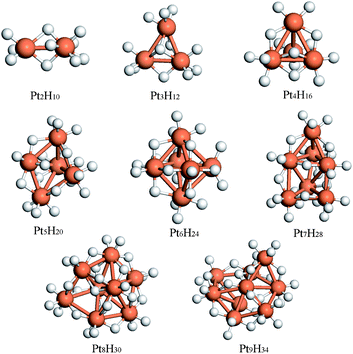 | ||
| Fig. 1 The fully optimized Pt clusters saturated with H atoms. | ||
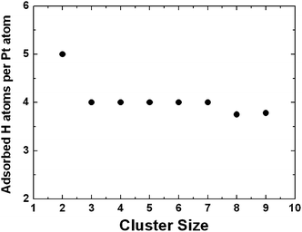 | ||
| Fig. 2 The average number of chemisorbed H atoms per Pt atom in small Pt clusters. | ||
Under the conditions of full H atom saturation, two critical properties of the small Pt clusters that determine the catalyst activities can be evaluated. The first property is the threshold H2 dissociative chemisorption energy, which describes the energy required to liberate a molecule of hydrogen from the cluster. The second property is the threshold H atom desorption energy, which determines how much energy is required to remove one H atom from the fully saturated cluster. Again, under a constant H2 pressure, once a H atom desorbs from the cluster, a H2 molecule will immediately undergo dissociative chemisorption to occupy the vacant site to maintain an overall cluster saturation equilibrium. Fig. 3 displays the calculated H2 dissociative chemisorption energies and H desorption energies at full H saturation for the small Pt clusters. We note that these energies do not change significantly as a function of cluster size. In particular, they essentially remain independent of where the H atoms are located on the cluster since the H2 dissociative chemisorption energy at full saturation is an average quantity and the H desorption energy is derived upon full structural relaxation. This is important and certainly deserves further investigation, since it seems to imply that these two threshold properties may remain more or less the same for large Pt particles, despite possessing much lower H : Pt aspect ratios, as for small clusters. We also note here that the threshold H desorption energy is the energy required to transfer a H atom from a fully H-saturated Pt cluster to the gas-phase as an atom, which is very large as anticipated. In the presence of an acceptor in close contact with the saturated Pt cluster where a concerted atom-transfer can occur, the H desorption energy would be expected to be significantly lower. In this case, H atom transfer energies will depend partially on the chemical properties of the specific substrate. Nevertheless, the calculated threshold H desorption energy is an important quantity that may serve as a reference for measuring catalytic activity.
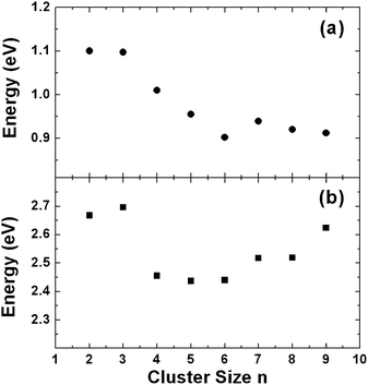 | ||
| Fig. 3 (a) H2 dissociative chemisorption energies at full H coverage; (b) H threshold desorption energies at full H coverage. | ||
Because of the remarkably small variation of the threshold H desorption energies with respect to the Pt cluster size, we decided to choose an octahedral Pt6 cluster to model the Pt particles for hydrogen spillover. The simple catalyst model, upon full H saturation, can greatly facilitate computational studies on hydrogen spillover at the catalyst–substrate interface and yield useful physical insight into the spillover mechanisms. Fig. 4 displays the calculated density of states for sequentially chemisorbed H atoms up to full cluster saturation. The Fermi level is shifted to zero and the main components of atomic orbitals that contribute to the low lying states are projected. For the bare Pt6 cluster, the 6s orbitals contribute only slightly to the valence band, which is largely dominated by the d-band. Upon H2 dissociative chemisorption, contribution of the Pt d-band to the valence band decreases with the H coverage, while contribution of the H 1s orbital to the valence band increases. In parallel, the d-band component in the conduction band increases considerably. The change of the electronic structure suggests that the d-electrons from the Pt6 cluster are partially but sequentially ionized and the H atoms act as the charge acceptor. It is also noteworthy that the valence band and the conduction band become increasingly separated with the H coverage as the bonding nature in the cluster changes from the metal–metal bonding to more covalent metal hydride bonding.
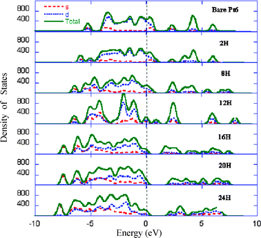 | ||
| Fig. 4 The calculated density of states for sequentially chemisorbed H atoms up to full cluster saturation. | ||
IV. Hydrogen spillover in MoO3
The structure of a MoO3 single crystal is comprised of layers of slabs in the (010) orientation (Fig. 5(a)). Each slab contains 4 layers of O atoms and 2 layers of Mo atoms. We selected a supercell containing one (2 × 2) MoO3 (010) layer and an 18 Å wide vacuum space to study spillover at the Pt cluster–MoO3 (010) interface (Fig. 5(b)), and subsequently investigated H diffusion between the slabs to understand bulk diffusion phenomenon. The validity of a one layer slab model for surface study is sustained by the fact that the MoO3 interlayer interactions are dominated by the van der Waals forces. Furthermore, our optimized Mo–O bond lengths in the relaxed single slab are virtually identical to those in bulk MoO3.109,110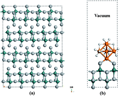 | ||
| Fig. 5 (a) The structure of a MoO3 single crystal is comprised of layers of slabs in the (010) orientation. Each slab contains 4 layers of O atoms and 2 layers of Mo atoms. (b) The selected supercell containing one (2 × 2) MoO3 (010) layer and 18 Å vacuum space for the study of hydrogen spillover at the Pt cluster–MoO3 (010) interface. | ||
We first carefully placed a fully H-saturated Pt6 cluster (shown in Fig. 1), with the bottom 4 H atoms removed, on the MoO3 (010) slab followed by structural optimization. Subsequently, we performed minimum energy path calculations to allow an H atom near the bottom of the cluster to migrate onto the substrate to form an O–H bond with a terminal O atom. The calculated energy profile is displayed in Fig. 6, and shows that a H atom can readily move, with a low activation energy barrier of 0.37 eV, from the H20Pt6cluster to a terminal oxygen atom to form an O–H bond. This indicates that the H atom desorption energy from the H-saturated Pt6 cluster can be significantly reduced by close contact with a substrate and a concerted atom transfer process. This hydrogen migration (H-migration) process is exothermic with a thermochemical energy of 0.21 eV. It is understood that there are numerous possible H adsorption configurations on the Pt6 cluster; however, our extensive computational tests suggest that the calculated H-migration barriers fluctuate only in a small range around 0.35 eV. The Bader charge analysis111 revealed that this barrier is a result of charge flows and protonation. In the initial state, each hydrogen atom adsorbed on Pt6 gains 0.05−0.15 electrons from Pt-5d bands, depending on its location on Pt6. The terminal oxygen atoms in MoO3 are negatively charged by 0.8−1.2 electrons. Thus, initially, the interaction between the H atoms on the saturated Pt cluster and the terminal O atoms is electrostatically repulsive. Upon the H migration onto the terminal oxygen, the electrons begin to transfer from the H-1s orbital to the O-2p orbital. The migrated H atom loses its electron and thus is positively charged (+0.96 electrons), essentially becoming a proton, in the final optimized conformation. Accordingly, the O atom gains an extra electron and this reduces the Mo–O bond strength, resulting in partial reduction of the Mo ion. The system undergoes a transition from repulsive O–H interactions to attractive proton–oxygen interactions along the migration pathway, resulting in a relatively small H-migration barrier. The calculated low activation energy clearly demonstrates the effectiveness of spillover in the H-migration process from the catalyst to the substrate.
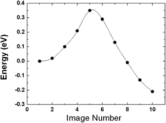 | ||
| Fig. 6 The calculated energy profile for H atom migration from the fully H-saturated Pt cluster to the terminal oxygen to form an O–H bond at the catalyst–MoO3 (010) interface. | ||
The energy profile shown in Fig. 6 describes only one of the H-migration pathways from the fully H-saturated Pt6 cluster to the MoO3(010) surface. Several other adsorption sites on the slab are also capable of binding with the H atom with similar migration profiles. The selected MoO3 slab comprises two symmetric Mo–O sheets (upper and lower) linked by strong Mo–O bonds. There are three structurally distinct lattice oxygen atoms on each sheet, i.e., terminal oxygen, symmetric bridging oxygen and asymmetric bridging oxygen as shown in Fig. 7. The sites labeled as Aupp,i and Alow, which are symmetrically equivalent, were found to be most favorable for H adsorption with an adsorption energy of 2.91 eV. The hydrogen atom bonds with the upper asymmetric oxygenvia a strong covalent bond (0.97 Å bond length) and also interacts with the lower asymmetric oxygenvia weaker H-bonding (at a distance of 1.7 Å). These results are consistent with the previous NMR and neutron diffraction studies by Ritter et al.89,90 and Dickens et al.91 which identified protons residing between the lower and upper asymmetric oxygens. Our results verify that it is thermodynamically and kinetically facile to form HxMoO3 bronze at the vicinity of Pt catalyst particles.
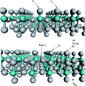 | ||
| Fig. 7 Three structurally distinct lattice O atoms on each slab, i.e., terminal oxygen, symmetric bridging oxygen and asymmetric bridging oxygen. | ||
Perhaps the most important step for realizing substantial hydrogen spillover on materials is the step in which the H atoms proximal to the catalyst particles migrate to sites away from where the metal particles are located. To study this step, we first explored the surface diffusion paths of a H atom within the selected slab. Fig. 8 displays the calculated minimum energy profile following one potential diffusion pathway of a H atom on MoO3. The first barrier corresponds to the diffusion across two adjacent terminal oxygen atoms. This calculated activation energy is 0.51 eV. This is a relatively low activation barrier and suggests that H atom migration on the MoO3 surface is facile at moderate temperatures. For example, the hopping rate of hydrogen between two adjacent terminal oxygen atoms is about 2.0 s−1 at room temperature, assuming a typical prefactor of 1013 s−1.112 The second barrier corresponds to the movement of the H atom from a terminal oxygen onto an upper asymmetric oxygen. This calculated activation energy is 0.6 eV. This slightly higher energy indicates that the diffusion from the terminal surface oxygen atom into the second layer is the rate-limiting step for the hydrogen bronze formation. The two binding modes are identified on the asymmetric oxygen atoms: Aupp,p and Aupp,i. Our calculation of the H-migration in the lattice reveals that the H atom is able to rotate around the <001> direction by 120° from Aupp,p to Aupp,i with nearly zero activation energy. The last activation barrier, corresponding to the migration from Aupp,i to Alow, is 0.35 eV. NMR experiments have suggested that at a low hydrogen content, protons in MoO3 reside between the lower and upper asymmetric oxygen sites and the diffusion activation energy was reported to be in the range 0.1−0.3 eV.89,113 Our calculated H diffusion barriers and the predicted relative thermodynamic stability of H adsorption sites in the lattice are in good agreement with these experimental observations. In the entire proton migration pathway, the highest activation barrier is no more than 0.6 eV, which clearly explains the high mobility of H in hydrogen bronze.
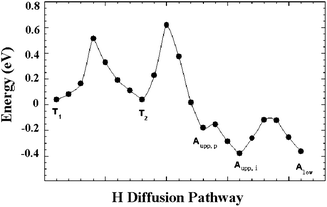 | ||
| Fig. 8 The calculated minimum energy profile following the selected diffusion pathways. | ||
To understand the low barriers for this H atom diffusion mechanism, we monitored the O–H distances during the H-diffusion process following the proton migration pathway. The calculated O–H distance distribution is displayed in Fig. 9, which reveals a massive H-bonding environment along the proton migration pathway in the lattice. The first peak at around 1.0 Å is attributed to the strong covalent O–H bonds at the stable binding modes. The second peak at 1.5 Å, which indicates weaker O–H interactions, can be attributed to non-covalent hydrogen bonding at or near the transition states. This suggests that the H-bonding interactions play a critical role in facilitating the proton migration in the lattice by reducing the activation barriers and increasing the H atom mobility. The shoulder in the plotted O–H distance distribution at 1.8−2.0 Å and the broad bands at distances greater than 2.0 Å are attributed to long-range oxygen–proton interactions with lower strengths. The extensive H-bonding network in the lattice provides a low energy barrier diffusion channel and thus enables the hydrogen atom to move between oxygen atoms at near-ambient temperatures. These results clearly indicate that H diffusion within the selected MoO3 slab is facile. To further understand the diffusivity of the H atom in the MoO3 bulk lattice, we continued our investigation of H migration through identification of pathways between two adjacent slabs. Fig. 10 displays the calculated minimum energy pathway to transfer one proton from the terminal oxygen located at the bottom T1 site of the upper slab to the top terminal site of the lower slab. These results indicate that diffusion of protons between slabs is energetically feasible and, therefore, H atoms can diffuse from the surface layers into the subsurface layers of bulk MoO3.
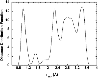 | ||
| Fig. 9 The calculated O–H distance distribution. | ||
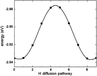 | ||
| Fig. 10 The calculated minimum energy pathway to transfer a H atom from the terminal oxygen located at the bottom T1 site of the upper slab to the top terminal oxygen site of the lower slab. | ||
The electronic structure of MoO3 exhibits a well-separated semiconductor-like band gap of 3.3 eV.114 It has been observed in many experiments that this semiconducting material is turned into a metal upon the formation of hydrogen bronze. To understand this transition, we calculated the energy band structure of MoO3 and H0.25MoO3. The calculated band structure for MoO3 (Fig. 11) exhibits a band gap of approximately 1.8 eV, in agreement with the experimental114 and previous ab initio computational results.115,116 Upon the hydrogen bronze formation, substantial change in the electronic structure is observed. The valence band is significantly widened, across the Fermi level into the conduction band. The electronic structure thus exhibits the typical band structure of a metal, in excellent agreement with the experimental observations. The origin of the change of electronic structure lies again in the extensive H-bonding environment, in which the protons bridge over the surrounding oxygen atoms for electron hopping.
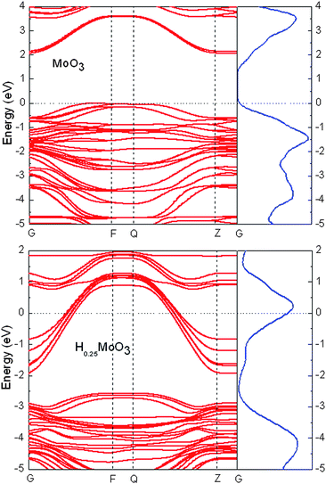 | ||
| Fig. 11 The calculated energy band structure of bulk MoO3 and H0.25MoO3. | ||
V. Hydrogen spillover in carbon-based materials
To examine hydrogen spillover in carbon-based materials, we selected several nanostructured carbon materials as the spillover substrates including a single graphene sheet, single walled carbon nanotubes (SWNTs), fullerenes, and hexabenzocoronene.110,117,118 The key issues we attempt to address in our computational studies are:(1) the minimum energy pathways for a H atom to migrate from the H-saturated Pt6 cluster to the substrates;
(2) the minimum energy pathways for a H atom to diffuse from a chemisorption site to another chemisorption site;
(3) the nature of H adsorption in graphitic carbon materials and dynamics;
(4) the influence of carbon material surface curvature on hydrogen storage capacity via spillover.
For simplicity, we will focus the majority of our discussions on hydrogen spillover on a graphene sheet. In the experiments conducted by Yang and co-workers, the Pt catalyst nanoparticles are attached to the substrate using a bridge material made of carbonized sugar, which is not incorporated in our theoretical model since its exact composition and structure are unknown.
Similar to the study on hydrogen spillover in MoO3, we first performed minimum energy pathway calculations by allowing two H atoms near the bottom of the fully saturated Pt6 cluster to migrate to the graphene sheet to form two C–H bonds. The calculated potential energy curve is shown in Fig. 12. The migration process is slightly endothermic with an average reaction energy of 0.23 eV per H atom. The calculated average activation barrier for the migration is 0.48 eV per H atom, which is moderate, indicating that the process is kinetically facile as well. These results suggest that H migration from a Pt catalyst to a graphene sheet in the vicinity of the catalyst could occur at moderate conditions and the close contact between the fully saturated Pt cluster and the graphene sheet can result in C–H bond formation.
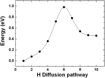 | ||
| Fig. 12 The calculated minimum energy pathway for two H atoms near the bottom of the fully saturated Pt6 cluster migrating to the graphene sheet to form two C–H bonds. | ||
The key question here is whether the H atoms, upon C–H bond formation, are capable of breaking the C–H bonds to diffuse to other sites of the graphene sheet. In Fig. 13, we label the C atoms to which a H atom chemisorbed on site 1 would migrate. For simplicity, only the case in which there is one C–H bond in the selected supercell was studied. It is anticipated that both the calculated reaction energies and activation barriers will be higher if more C–H bonds are present in the supercell since a higher number of C–H bonds can result in more energetically favorable conformations for the hydrogenated graphene. Fig. 14 displays the calculated potential energy curves for a H atom to move from a C atom (site 1) to an adjacent C atom (site 2) and from site 1 to site 4 as shown in Fig. 13. The calculation yields an activation energy of 0.78 eV for diffusion from site 1 to site 2, which is close to the adsorption energy but only slightly lower than the activation energy required to desorb a H atom from the carbon surface. It might have been anticipated that a concerted atom-transfer reaction to move a hydrogen between adjacent carbon atoms on the sheet could lower the energy barrier relative to the H atom dissociation energy. However, this result indicates that the C–H bond needs to be broken in a largely non-concerted process in order for the H atom to move. This stringent requirement of course hinders the H diffusion. After the completion of H atom diffusion, the ‘puckered’ (out of the graphene plane) carbon atom from the original C–H bond moves back toward its original lattice site. Simultaneously, the adjacent carbon atom is pulled out of the graphene plane to form a new C–H bond. For H diffusion from site 1 to site 3, the calculated minimum energy pathway indicates that the H atom must pass through site 2. Therefore, the calculated potential energy curve for the diffusion pathway is simply a duplicate of the energy curve for diffusion from site 1 to site 2. For H diffusion from site 1 to site 4, the calculated potential energy exhibits a double-hump shape representing essentially three consecutive steps. First, the H atom is desorbed from the surface. Second, the H atom is adsorbed at a metastable site above the center of the hexagonal ring. Finally, the H atom reaches its destination by forming a strong C–H bond at site 4. The rate-limiting step is the transition from the chemisorption state to the meta-stable site with a barrier of 0.95 eV, which is slightly higher than the activation energy of diffusion between two adjacent sites. Considering the small energy difference of 0.17 eV between the diffusion pathways for site 1 to site 2 and site 1 to site 4, it is likely that the two diffusion pathways could coexist at high temperatures. We have also investigated several possible diffusion routes for two H atoms chemisorbed on opposite sides of two neighboring C atoms in graphene starting from the optimized co-adsorption structure. It was found that even the lowest activation energy is larger than 1.5 eV. We thus conclude that the concerted motion of two H atoms is not energetically feasible. Our results are consistent with the recent report using scanning tunneling microscopy and DFT calculations to study diffusion of two separated H atoms on a graphite (0001) surface which concluded that simultaneous diffusion of two H atoms is energetically unfavorable.119
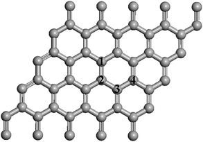 | ||
| Fig. 13 The graphene sheet showing H adsorption and diffusion sites. | ||
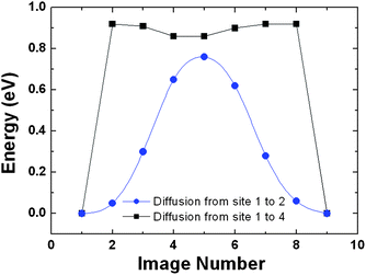 | ||
| Fig. 14 The calculated potential energy curves for a H atom to move from a C atom (site 1) to an adjacent C atom (site 2) and from site 1 to site 4. | ||
We performed the same diffusion pathway calculations for H atom diffusion along the longitudinal (from site 1 to 3) and horizontal (from site 1 to 2) directions on (5,5) and (9,9) armchair SWNT surfaces. The calculated minimum energy profiles for H atom diffusion on SWNT are similar to those for graphene. However, the calculated diffusion barriers on SWNTs are considerably higher than that in graphene. The calculated results are shown in Table 2, where the H atom adsorption energies along with the C–H bond lengths are also listed. The calculated diffusion barriers are very close to the corresponding adsorption energies, which again indicates the need for complete C–H bond dissociation for diffusion. The calculated energy profiles reflect a strong influence of the SWNT curvatures on the barriers to H atom surface diffusion. A high nanotube curvature positively enhances the adsorption strength (C–H bond energy) and thus also significantly reduces the possibility of mobility of H atoms on the surface. When compared with the results for the graphene sheet, it appears that it is more difficult for the H atom to diffuse on the carbon atoms in SWNT with sp3-like C–C–C bond angles.
| Graphite | (5,5) SWNT | (9,9) SWNT | |
|---|---|---|---|
| H diffusion barrier/eV | 0.78 | 1.09 | 1.42 |
| H adsorption energy/eV | 0.82 | 1.07 | 1.43 |
| C–H bond length/Å | 1.12 | 1.11 | 1.12 |
Finally, we considered H diffusion from an inner site to the edge of hexabenzocoronene. The calculated energy landscape diagram of adsorption and transition states is shown in Fig. 15. The calculated diffusion activation energies from site 1 to site 2 and from site 2 to site 3 are 1.52 and 1.42 eV, respectively. These activation energies are much higher than those calculated for the graphene sheet but similar to the activation energies for H atom diffusion on the exterior wall of (5,5) SWNT. The diffusion is accompanied by considerable structural changes in the molecule in order to accommodate the change of electronic configuration of the carbon atom in the C–H bond from sp2 to sp3 hybridization. The bond angle changes within the molecule as well as the diffusion on the sp3 carbons significantly increases the activation energy. In contrast, H atom diffusion on the flat graphene sheet and exterior walls of SWNTs causes more localized bond angle deformations and a smaller extent of structural relaxation in these more rigid structures, in which only the carbon atom in the C–H bond and a few adjacent carbon atoms are involved.
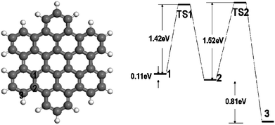 | ||
| Fig. 15 H diffusion from an inner site (site 1) to the edge of hexabenzocoronene and the calculated energy landscape diagram of adsorption and transition states. | ||
These results for surface diffusion of a chemisorbed H atom on graphene, SWNTs and a small polyaromatic molecule clearly demonstrate that hydrogen spillover based on a chemisorption mechanism would be energetically difficult. Therefore, we explored another possibility for H atom diffusion via physisorption. It was recently reported by Ye and Chiu that atomic hydrogen is mobile on graphite at room temperature, based on their observation in the experiment of graphite mediated reduction of azoaromatic compounds with elementary iron in lialysis cells.120 DFT calculations by Sha and Jackson121 suggests that there is an energy barrier to forming a C–H bond of approximately 0.2 eV when a H atom approaches a graphite surface. The barrier arises from the structural stresses induced by pulling the C atom out of the graphene plane. If the H atom remains “hot” (i.e. has enough kinetic energy) after dissociation, transfer from the catalyst, and diffusion across the surfaces of the support and bridges, this activation barrier can be readily overcome and a C–H bond would then be formed. However, if the atom becomes kinetically “cold”, it will be blocked by the activation barrier, located approximately 2.5 Å above the graphene plane, and the H atom can only be physisorbed.122,123 We suspect that the high mobility of the H atoms observed in Ye and Chiu's experiment is due to the diffusion of physisorbed H atoms. Indeed, our calculated physisorption energy for a H atom on the graphene sheet and the selected SWNTs is less than 0.1 eV. Fig. 16 displays the calculated potential energies in the physisorption region. The potential energy is rather flat, indicating a site-independent behavior. In other words, if the H atom is physisorbed on graphene, it can move across the plane with minimal energy changes. It is important to point out that H atom physisorption arising from the van der Waals force cannot be accurately described by DFT. Nevertheless, regardless of the computational methods used in the calculations, the adsorption energy is obviously very small, as qualitatively indicated in our results. Therefore, we believe that the only viable mechanism for hydrogen spillover in graphitic carbon materials is viaH physisorption.
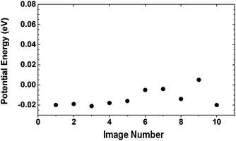 | ||
| Fig. 16 The calculated potential energies for the movement of a physisorbed H atom across the graphene surface. | ||
How stable are the weakly bound physisorbed H atoms on the graphitic carbon materials? To understand their thermal and chemical stability, we attempted to qualitatively address the dynamics of these atoms by performing ab initio molecular dynamics simulations at room temperature. A key issue is how fast and to what extent these atoms will remain highly mobile free radicals, recombine to form molecular hydrogen, or form C–H bonds with the substrates. An additional interesting issue is whether the substrate structures influence the spillover efficiencies. To simplify the simulations, we selected a single graphene sheet and C60 to examine the dynamic behavior of an assembly of physisorbed H atoms.
We performed a MD simulation of H atoms in a sufficiently large rectangular box containing a single graphene sheet. The unit cell, shown in Fig. 17, contains 50 C atoms in the graphene sheet sandwiched by 4 H atom layers, two above and two below. Each H atom layer includes 9 physisorbed H atoms separated by at least 4.0 Å from each other to prevent the atoms from rapid recombination to form H2 molecules. The vacuum spacing separating the sheets was set at a distance of 25 Å to minimize inter-sheet interactions. With the activation barrier for H atom chemisorption on the substrate in mind,121,122 we set the initial position of the inner H atom layers at distances of 2.5, 2.75 and 3 Å from the substrate, respectively, and the outer H layers at a spacing of 4 Å from the inner H layers. Admittedly, these initial structural arrangements are rather arbitrary; however, other physisorption configurations should not change the total potential energies significantly as long as the H atoms remain in the physisorption region. Nevertheless, kinetically, reactive events may vary depending on the relative positions of atoms in the unit cell. In addition, MD simulations on such a small unit cell are not statistically significant. Our main interest here is to find out qualitatively whether an assembly of physisorbed H atoms is capable of interacting with these substrates, including forming C–H bonds, at a near-ambient temperature. Our MD simulation results indicate that for the inner H-layers located 2.5 Å from the substrate, the strong attraction between H atoms and the substrate steers the H atoms in the inner layers towards the graphene immediately and most of the H atoms in these two layers become chemisorbed after 0.25 ps (Fig. 18(a)). The substrate structure undergoes substantial relaxation and the interacting C atoms pucker out of the plane to form C–H bonds with a bond length of approximately 1.15 Å, consistent with the previous DFT study.121,124 In parallel, most of the H atoms in the outer layers rapidly form H2 molecules, which subsequently become weakly physisorbed on the graphene sheet. For the chemisorbed H atoms, no further diffusion to other chemisorption sites was observed during the 4 ps simulation time. However, Eley–Rideal recombination,125,126 in which a gas-phase H atom strikes a C–H bond to form an H2 molecule, was observed, indicating that the surface C–H bonds are rather weak compared with the C–H bonds in organic molecules. We found that Eley–Rideal recombination on the graphene sheet is a significant process that results in depletion of the chemisorbed H atoms from the substrate. Indeed, at 4 ps, the number of the surface H atoms is actually reduced compared with the number at 0.25 ps (Fig. 18(b)). The remaining C–H bonds are not well ordered with respect to each other on the graphene sheet, despite the fact that the structural configuration with alternative C–H bonds on graphene, i.e. one C–H bond above the plane adjacent to another C–H bond below the plane, is thermodynamically more favorable than the structure with randomly distributed isolated C–H bonds.127 This suggests that the chemisorption process is kinetically controlled.
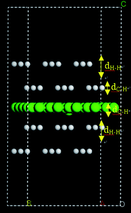 | ||
| Fig. 17 The unit cell selected for MD simulations of physisorbed H atoms interacting with a graphene sheet. | ||
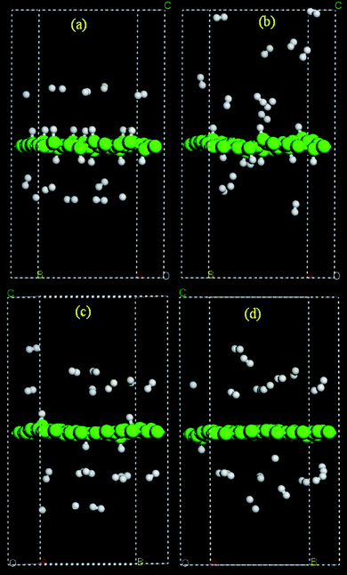 | ||
| Fig. 18 MD simulation snapshots for H atoms on a graphene sheet at (a) 0.25 and (b) 4 ps for the initial configuration with nearest C–H layer distance at 2.5 Å, and at 0.25 ps for an initial distance at 2.75 (c) and 3.0 (d) Å. | ||
Moving the layers of H atoms from their original positions by 0.25 Å and 0.5 Å, respectively, along the direction away from the graphene sheet yielded a drastically smaller number of chemisorbed H atoms on the graphene sheet in our MD simulations (Fig. 18(c) and (d)). This is largely due to the fact that the hydrogen atoms are now located at a distance from the graphene which is outside the distance associated with the C–H bond formation energy barrier (ca. 2.5 Å) and, more importantly, the recombination of H atoms to form H2 molecules is barrierless and thus a thermochemically and kinetically more favorable competitive process. Therefore, the kinetics of C–H bond formation are sensitive to the relative initial distance between H atoms and C atoms in the MD simulations. A short distance increases the probability for an H atom to form a C–H bond and a long distance gives rise to a higher probability for H2 recombination reaction. Morisset et al. examined the formation of the H2 molecule through two initially physisorbed atoms on a graphite surface via quantum wave packet method, and reported that the reaction occurs with a significant probability,128,129 which is consistent with what is observed in our MD simulations. The calculated numbers of events are summarized in Table 3. Despite the lack of statistical significance of the current method due to a small number of atoms used in the theoretical model and the relatively short simulation time, it can be qualitatively concluded that the transition from physisorbed H atoms to a chemisorption of hydrogen atoms on a graphene sheet can occur at room temperature. In a closed system with a metal catalyst (as in the published hydrogen spillover experiments), H2 molecules formed viaH atom recombination could again interact with the metal catalyst to regenerate H atoms.
| Substrate | N H | D C–H/Å | Time/ps | Chemisorbed state | Physisorbed state | Molecular state |
|---|---|---|---|---|---|---|
| Graphite | 36 | 2.5 | 0.25 | 15 | 7 | 14 |
| 1 | 10 | 8 | 18 | |||
| 4 | 10 | 2 | 24 | |||
| 2.75 | 0.25 | 4 | 6 | 26 | ||
| 3.0 | 0.25 | 1 | 7 | 28 | ||
| 1 | 1 | 3 | 32 | |||
| C60 | 50 | 3.2 | 0.1 | 1 | 23 | 26 |
| 1 | 4 | 24 | 22 | |||
| 1.5 | 6 | 8 | 36 |
To understand the structural effects of the carbon substrates on H spillover, we performed a MD simulation for an assembly of H atoms on C60 confined in a sufficiently large box at 300 K. The unit cell parameters were set at 27.34 Å and the number of H atoms in the box was set at 50. The initial positions of the H atoms were 4.0 Å apart from each other and the distance between H atoms and C60 was set to be at least 3.2 Å. Similar to the case of the simulation involving graphene, all H atoms exhibit high mobility upon the start of the MD simulations, suggesting that H diffusion in the physisorption state is facile. However, shortly after MD initiation, both H chemisorption that leads to formation of C–H bonds and H recombination to form H2 take place almost simultaneously. Of the 50 H atoms in the box, 6 of them become chemisorbed and the rest form H2 molecules (Table 3). Fig. 19 displays several snapshots of the MD trajectory. The chemisorption of hydrogen atoms on C60 appears to be much easier compared to chemisorption on graphene, as evidenced by the fact that more H atoms form C–H bonds on C60. This is likely due to a lower barrier to C–H bond formation for adsorbed H atoms and more favorable thermochemical C–H bond energy resulting from carbon curvature.130,131
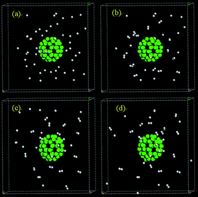 | ||
| Fig. 19 MD simulation snapshots for H atoms on C60 at (a) 0, (b) 0.1, (c) 1, and (d) 1.5 ps. | ||
The MD studies of H spillover dynamics on graphene and C60 qualitatively indicate that physisorption of H atoms facilitates H diffusion and ultimately leads to either H chemisorption or H2 formation as time evolves. The spillover efficiency (i.e. the percentage of adsorbed H atoms that form C–H bonds) depends on the curvature of the substrates. Our MD simulations indicate that the efficiency of hydrogenation of graphitic materials could be enhanced with carbon materials with curved surfaces (e.g. fullerenes). To gain additional understanding of this ‘curvature effect’ we examined the hydrogenation energies of fullerenes with various sizes where the hydrogenation takes place at the exohedral sites.
To understand the energetics required to partially or fully hydrogenate fullerenes, we calculated the average C–H bond energies at various levels of hydrogenation. The results are shown in Fig. 20 and the optimized fully hydrogenated fullerene structures are displayed in Fig. 21. Upon hydrogenation, the C–C bond distances of fullerenes increase slightly as the hybridization of the C atoms changes from sp2 to sp3 and the C–H bond lengths (1.095 Å) are similar for all the nine fully hydrogenated fullerenes. To form only one C–H bond per fullerene, the C–H bond energy essentially decreases with fullerene size, reflecting the strong influence of carbon material curvature on the C–H bond strength. The only exception is C32, on which the C–H bond is in fact weaker than on C44. A detailed analysis indicates that the surprisingly weaker C–H bond in C32 arises from the exceptionally stable electronic structure of C32. C32 has been known to be much more stable than other small fullerene molecules except C60.132,133Ultraviolet photoelectron spectroscopy of C32 and C60 exhibits unusually large HOMO–LUMO gaps of 1.3 eV and 1.6 eV, respectively.134 In contrast, the HOMO–LUMO gaps of other fullerene molecules are much smaller, ranging from 0.70−0.80 eV. The calculated HOMO–LUMO gaps of the selected fullerenes, shown in Table 4, compare well with the experimentally measured values. We also note that the C–H bond energy in C20 is substantially larger than those in other fullerenes, resulting from the highly acute C–C–C bond angles of the carbon atoms, causing these atoms to behave like radicals. For higher percentages of hydrogenation of the fullerenes, the calculated C–H bond energies decrease monotonically with the fullerene size. For larger fullerenes, the average C–H bond energy varies in a relatively small range, roughly within 0.4 eV, with respect to hydrogenation percentage; a considerably larger variation of C–H bond energies vs. hydrogenation percentage for smaller fullerenes, particularly C20, was found since these fullerenes exhibit higher reactivity. Compared with the typical C–H bond energy in organic molecules (∼4.3 eV), the average C–H bond energies in fullerenes, except C20, are much smaller. Nevertheless, our results suggest that hydrogenation of fullerenes by physisorbed H atoms is a highly exothermic process. As the fullerene size decreases, the well-depth of C–H bond formation increases. It is therefore anticipated that hydrogenation of the fullerenes will become increasingly facile as the fullerene size decreases but dehydrogenation will be increasingly more difficult. Table 5 displays the calculated average energy of forming H2 molecules from the selected hydrogenated fullerenes (CnHm) at a given capacity, defined by
| Molecules | HOMO–LUMO gap/eV | |
|---|---|---|
| Calculation | Experiment | |
| C20 | 0.37 | — |
| C28 | 0.78 | — |
| C32 | 1.43 | 1.3 |
| C36 | 0.45 | 0.8 |
| C40 | 0.88 | 0.7 |
| C44 | 0.85 | 0.8 |
| C48 | 0.73 | — |
| C60 | 1.67 | 1.6 |
| C70 | 1.72 | 1.3 |
| Molecules | Hydrogenation percentage (%) | ||||
|---|---|---|---|---|---|
| 20 | 40 | 60 | 80 | 100 | |
| C20 | 2.34 | 2.96 | 1.98 | 2.3 | 2.68 |
| C32 | 1.58 | 1.3 | 1.1 | 1.3 | 1.6 |
| C44 | 0.86 | 0.56 | 0.44 | 0.8 | 1.06 |
| C60 | 0.12 | 0.32 | 0.06 | 0.3 | 0.46 |
| C70 | 0.02 | 0.2 | −0.04 | 0.18 | 0.26 |
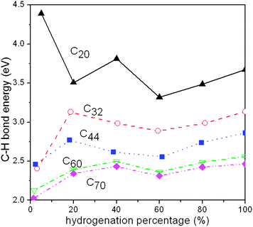 | ||
| Fig. 20 The calculated average C–H bond energy as a function of hydrogenation percentage in several selected fullerene molecules. | ||
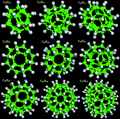 | ||
| Fig. 21 Optimized configurations for nine fully hydrogenated fullerenes, C20H20, C28H28, C32H32, C36H36, C40H40, C44H44, C48H48, C60H60, and C70H70. | ||
In all cases, desorption is an endothermic process and, as expected, the desorption energy decreases with increasing fullerene size. In particular, at 80% to full hydrogen saturation, the required desorption energy for C60 and C70 appear to be quite small. Of course, the key challenge to make these materials useful for hydrogen storage is to find a catalytic process that allows the C–H bonds to be broken easily.
VI. Hydrogenation of coronene
Upon casual reflection, the polyaromatic hydrocarbon, coronene, represents a small section of a graphene sheet (inset, Fig. 22). This highly symmetrical molecule has the maximum possible number of aromatic sextets for a 7-ring PAH due to the circular shape, which leads to greater aromatic stabilization for coronene than other PAH with the same number of rings.96 Significant differences will exist between coronene and “true” graphene including electronic differences (e.g. ionization energy), enthalpy of hydrogenation, and ordering in the solid state (i.e. crystal structure of coronenevs. graphite). Regardless, we have chosen coronene for our studies of hydrogenationviahydrogen spillover as it represents one of the largest PAHs that is readily available and is amenable to analytical characterization by NMR and gas chromatography-mass spectroscopy (GC-MS). In our experimental studies, we have observed the hydrogenation of coronene in the solid state at temperatures substantially below the melting point. Intimate mixtures of coronene (melting point 428 °C) and heterogeneous hydrogenation catalysts were exposed to moderate pressures of hydrogen at 150 °C, resulting in the formation of partially hydrogenated derivatives of coronene.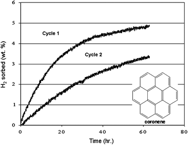 | ||
| Fig. 22 The reversible catalytic solid-state hydrogenation of coronene with palladium nanoparticles over two cycles. The inset shows the molecular structure of coronene. | ||
A sample of coronene was impregnated with palladium metal particles by RF sputtering. Subsequent thermal gravimetric combustion analysis demonstrated a 3% loading of palladium metal in the coronene solid. The sample was then placed in a differential pressure adsorption unit, consisting of two identical pressure cells which are spanned by a differential pressure gauge.135 Under 995 psia of hydrogen gas pressure at 150 °C, a 4.9 wt% increase of the gravimetric hydrogen capacity on a total sample weight basis (coronene + catalyst) was observed over a period of 63 h (Fig. 22, cycle 1). The mixture of hydrogenated coronene compounds were dehydrogenated, under 20 psia hydrogen gas pressure, at temperatures of 150 °C and 200 °C in the absence of any mechanical agitation or grinding (Fig. 23(a)). After 24 h at 150 °C and 14 h at 200 °C, the sample desorbed 4.5 wt% hydrogen (92% of the sorbed hydrogen). The sample was hydrogenated a second time; under 1005 psia of hydrogen gas pressure at 150 °C, a 3.9 wt% increase of the gravimetric hydrogen capacity on a total sample weight basis (coronene + catalyst) was observed over a period of 91 h (Fig. 20, cycle 2, data shown only up to 60 h). The mixture of hydrogenated coronene compounds were again dehydrogenated, under 20 psia hydrogen gas pressure, at 200 °C (Fig. 23(b)). After 9 h at 200 °C, the sample desorbed 3.5 wt% hydrogen (90% of the sorbed hydrogen). These results appear to demonstrate an advantage of gas/solid hydrogenation and dehydrogenation of a two component solid system (hydrogenated and dehydrogenated forms of the solid substrate) in that the hydrogenation and dehydrogenation of the solid can easily and effectively go to completion under equilibrium conditions.
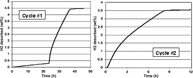 | ||
| Fig. 23 Desorption of hydrogen from hydrogenated coronene over two cycles via solid-state catalytic dehydrogenation with palladium nanoparticles. | ||
Other metal catalysts were also found to be effective for the hydrogenation and dehydrogenation of coronene in the solid state. In one representative experiment, a 2 : 1 mixture of coronene and rhodium on carbon catalyst (5% Rh) were ground with an agate mortar and pestle for 15 min until a uniform mixture was formed. The sample was degassed at ambient temperature for 30 min under vacuum. Both the sample cell and reference cells were placed under 970 psia hydrogen and heated to 150 °C. The hydrogen pressure in the sample cell dropped, relative to the reference cell, for a period of 17 h, indicating adsorption of 3.2 wt% hydrogen by the sample. After 17 h, the cells were cooled to ambient temperature and the pressure in both cells reduced to 20 psia. Upon heating both cells to 150 °C, there was a increase in the pressure of the sample cell relative to the reference cell, indicating desorption of hydrogen from the sample. After 70 h, the sample had desorbed 1.0 wt% hydrogen (31% of the sorbed hydrogen). Analysis of the sample after hydrogenation/dehydrogenation by GC-MS confirmed that partially hydrogenated intermediates of coronene were present in the sample.
The coronene/catalyst mixtures described in these examples have a number of things in common with carbon-based samples where hydrogen spillover has been reported in the literature. Dispersed metal nanoparticles (palladium or rhodium), ‘bridge’ materials (activated carbon in the example of the rhodium on carbon catalyst), and a hydrogen acceptor (i.e. an unsaturated aromatic material that can form stable C–H bonds) are present in the sample. In our experiments, there were no solvents employed and no physical means of moving catalyst particles throughout the solid organic compound (e.g. no grinding of the mixture under hydrogen). In the absence of means to transport the coronene to the heterogeneous hydrogenation catalyst (e.g. dissolving the organic compound in a solvent or sublimation of the coronene) or a means of transporting the hydrogenation catalyst to the solid coronene, it has to be considered that the mobile species is the atomic hydrogen generated by hydrogen dissociation. The conclusion, therefore, is that coronene hydrogenation is the result of C–H bond formation by H atoms in a hydrogen spillover-related phenomenon. The observed dehydrogenation of the hydrogenated coronene is more poorly understood in the context of breaking relatively strong C–H bonds in the absence of directly metal-mediated catalytic reactions.
VII. Summary
It has been widely recognized that hydrogen storage is one of the key technologies for realizing onboard applications of PEM fuel cells. Hydrogen spillover in lightweight element materials has emerged as an important technique for storing hydrogen with a significant capacity at near-ambient conditions. Understanding the underlying spillover mechanisms is of essential importance for the design and development of novel hydrogen storage materials that will assist in meeting the DOE hydrogen storage system targets. In this review, we present our mechanistic studies on hydrogen spillover in selected transition metal oxides and a few nanostructured graphitic carbon-based materials. Mechanistically, the hydrogen spillover process includes three consecutive steps. In the first step, H2 molecules undergo dissociative chemisorption upon interacting with metal catalysts. Subsequently, H atoms on the catalyst surfaces migrate to the substrate in the vicinity of the catalyst particles. Finally, H atoms near the catalysts diffuse freely to the surface or bulk sites far from where the catalyst particles reside. We attempted to address every step of the spillover process and our combined quantum-mechanical first-principles calculations and catalytic hydrogenation and dehydrogenation experiments for solid state polycyclic aromatic hydrocarbon compounds represent a comprehensive description of hydrogen spillover process in the chosen solid state materials.Theoretically, we first employed a simple Pt cluster model to represent the Pt catalyst nanoparticles and examined H2 dissociative chemisorption on the cluster until it was fully saturated by H atoms. The small cluster model is, of course, a gross simplification of realistic size of catalyst particles and does not resemble the catalyst particles used in practice. However, it has the following advantages over the conventional crystalline surface model, which has been widely used in computational modeling of heterogeneous gas–solid catalytic reactions in the literature.
(1) The cluster model possesses sharp corners, edges and kinks, which are often found to be the most active catalytic sites in experimental and computational studies.
(2) The cluster model allows us to computationally investigate the effects of full coverage of chemisorbed gas species on catalytic activities. At a given gas pressure, the active catalyst surfaces are expected to be fully covered with hydrogen.
(3) The cluster model provides an opportunity to examine chemistry at the catalyst–substrate interface, which would be otherwise very difficult to model computationally.
Our computational results from H2 dissociative chemisorption on the selected small Pt clusters suggest that at full H-saturation the H2 dissociative chemisorption energy and the H-desorption energy do not change significantly with the cluster size. This is very important because it allows us, with more confidence, to use a small cluster to explore how H atoms are transferred from the catalyst to the solid substrate, thus gaining insight into the interface chemistry. Due to computational limitations, the present study deals with only small Pt clusters at the subnano scale. Further in-depth investigations on the catalytic properties of larger Pt clusters at full saturation of H atoms are necessary in future studies to gain full understanding of the catalyst size effects.
We utilized a fully H-saturated Pt cluster to explore the energetic profiles of H migration from the cluster to its vicinity on the substrate surfaces. On the MoO3(010) surface, the H-migration was found to be facile with a moderate activation barrier and an exothermic reaction energy. As the H atom migrates from the Pt cluster to the substrate, it gradually loses its electron to the accepting O atom and becomes a proton upon forming HxMoO3. Consequently, the Mo atom bonded to the accepting O atom is reduced. We showed that H atoms can readily diffuse on the surfaces of a MoO3 slab and between the adjacent slabs into the bulk lattice. Assisting the facile hydrogen spillover is an extensive H-bonding network inherent to the MoO3 lattice capable of accommodating protons after H atom transfer from the Pt catalyst surfaces. Our calculated H-diffusion barrier in bulk MoO3 is in excellent agreement with the available NMR experimental data. Upon formation of the hydrogen bronze, the semiconductor-like electronic structure of MoO3 was found to exhibit a zero band gap, consistent with experimental observations. For the first time, the complete mechanism that dictates hydrogen spillover processes in the transition metal oxides is conclusively understood.
The hydrogen spillover in nanostructured graphitic carbon materials was found to be distinctively different than in transition metal oxides. Three graphitic carbon materials (a graphene sheet, SWNT, and hexabenzocoronene), representing both finite and extended systems, were selected for our computational studies. H atom migration from the fully H-saturated Pt cluster to a graphene sheet to form a C–H bond was found to be facile with a moderate activation barrier and a moderate endothermic energy. However, H atom diffusion initiated from a chemisorbed hydrogen on the graphene sheet was found to be energetically difficult since it requires breaking the strong C–H bond prior to forming another C–H bond. H atom diffusion based on chemisorption is even more difficult on a carbon material with curved surfaces, e.g.SWNT, and in finite polyaromatic complexes such as hexabenzocoronene since it requires more energy to break the even stronger C–H bonds to make the H atom move to an adjacent site. We thus conclude that hydrogen spillover would not occur via the a chemisorption-only process involving consecutive C–H bond breaking and formation. We showed that a kinetically “cold” H atom generated by the fully H-saturated Pt cluster can be blocked by an activation barrier for forming a C–H bond and thus the atom can be physisorbed on the graphene sheet. Physisorbed H atoms can freely diffuse across the graphene sheet without experiencing significant energy variations. We thus conclude that hydrogen spillover in graphitic carbon materials can only occur if the H atoms generated from Pt catalyst particles upon H2 dissociative chemisorption migrate to sites distant from the catalyst particle via physisorption. Our results indicate that H atom physisorption is metastable and the H atoms will quickly undergo either recombination to form H2 molecules or hydrogenation to form C–H bonds with the substrates. We find that the carbon material surface curvature and the electronic structure of the substrates strongly influence the hydrogen storage capacity and hydrogen desorption properties.
Intimate mixtures of coronene and heterogeneous transition metal catalysts were used to demonstrate reversible hydrogenation of coronene at reaction temperatures several hundred degrees Celsius below the melting point of the solid, favoring our interpretation of solid-state hydrogenation. These experimental studies of the solid-state hydrogenation of a graphene-like large polyaromatic hydrocarbon add experimental evidence for the migration of hydrogen atoms in a solid-state material and the ability of hydrogen atoms to hydrogenate an aromatic carbon-based material in the absence of direct metal-mediated catalytic hydrogenation.
Acknowledgements
The authors gratefully acknowledge partial funding for this work provided by the US Department of Energy's Office of Energy Efficiency and Renewable Energy via the Hydrogen Sorption Center of Excellence (contract DE-FC-05GO15074) and an independent hydrogen storage project (contract DE-FC36-04GO14006). The Government reserves for itself and others acting on its behalf a royalty-free, nonexclusive, irrevocable, worldwide license for Governmental purposes to publish, distribute, translate, duplicate, exhibit and perform this copyrighted paper.References
- P. Costamagna and S. Srinivasan, J. Power Sources, 2001, 102, 242 CrossRef CAS.
- P. Costamagna and S. Srinivasan, J. Power Sources, 2001, 102, 253 CrossRef CAS.
- V. Mehta and J. S. Cooper, J. Power Sources, 2003, 114, 32 CrossRef CAS.
- T. V. Nguyen and R. E. White, J. Electrochem. Soc., 1993, 140, 2178 CrossRef CAS.
- H. M. Cheng, Q. H. Yang and C. Liu, Carbon, 2001, 39, 1447 CrossRef CAS.
- F. L. Darkrim, P. Malbrunot and G. P. Tartaglia, Int. J. Hydrogen Energy, 2002, 27, 193 CrossRef CAS.
- A. C. Dillon and M. J. Heben, Appl. Phys. A: Mater. Sci. Process., 2001, 72, 133 CrossRef CAS.
- M. S. Dresselhaus, K. A. Williams and P. C. Eklund, MRS Bull., 1999, 24, 45 CAS.
- W. Grochala and P. P. Edwards, Chem. Rev., 2004, 104, 1283 CrossRef CAS.
- S. M. Lee and Y. H. Lee, Appl. Phys. Lett., 2000, 76, 2877 CrossRef CAS.
- U. Mueller, M. Schubert, F. Teich, H. Puetter, K. Schierle-Arndt and J. Pastre, J. Mater. Chem., 2006, 16, 626 RSC.
- M. G. Nijkamp, J. Raaymakers, A. J. van Dillen and K. P. de Jong, Appl. Phys. A: Mater. Sci. Process., 2001, 72, 619 CrossRef CAS.
- J. L. C. Rowsell and O. M. Yaghi, Angew. Chem., Int. Ed. Engl., 2005, 44, 4670 CrossRef CAS.
- L. Schlapbach and A. Zuttel, Nature, 2001, 414, 353 CrossRef.
- A. M. Seayad and D. M. Antonelli, Adv. Mater., 2004, 16, 765 CrossRef CAS.
- M. Terrones, Annu. Rev. Mater. Res., 2003, 33, 419 CrossRef CAS.
- J. Weitkamp, M. Fritz and S. Ernst, Int. J. Hydrogen Energy, 1995, 20, 967 CrossRef CAS.
- A. Zuttel, P. Sudan, P. Mauron, T. Kiyobayashi, C. Emmenegger and L. Schlapbach, Int. J. Hydrogen Energy, 2002, 27, 203 CrossRef CAS.
- C. C. Ahn, Y. Ye, B. V. Ratnakumar, C. Witham, R. C. Bowman and B. Fultz, Appl. Phys. Lett., 1998, 73, 3378 CrossRef CAS.
- A. S. Arico, P. Bruce, B. Scrosati, J. M. Tarascon and W. Van Schalkwijk, Nat. Mater., 2005, 4, 366 CrossRef CAS.
- R. H. Baughman, A. A. Zakhidov and W. A. de Heer, Science, 2002, 297, 787 CrossRef CAS.
- A. Chambers, C. Park, R. T. K. Baker and N. M. Rodriguez, J. Phys. Chem. B, 1998, 102, 4253 CrossRef CAS.
- B. L. Chen, N. W. Ockwig, A. R. Millward, D. S. Contreras and O. M. Yaghi, Angew. Chem., Int. Ed. Engl., 2005, 44, 4745 CrossRef CAS.
- J. Chen, N. Kuriyama, H. Yuan, H. T. Takeshita and T. Sakai, J. Am. Chem. Soc., 2001, 123, 11813 CrossRef CAS.
- P. Chen, X. Wu, J. Lin and K. L. Tan, Science, 1999, 285, 91 CrossRef CAS.
- P. Chen, Z. T. Xiong, J. Z. Luo, J. Y. Lin and K. L. Tan, Nature, 2002, 420, 302 CrossRef CAS.
- A. C. Dillon, K. M. Jones, T. A. Bekkedahl, C. H. Kiang, D. S. Bethune and M. J. Heben, Nature, 1997, 386, 377 CrossRef CAS.
- K. J. Gross, P. Spatz, A. Zuttel and L. Schlapbach, J. Alloys Compd., 1996, 240, 206 CrossRef CAS.
- B. Kesanli, Y. Cui, M. R. Smith, E. W. Bittner, B. C. Bockrath and W. B. Lin, Angew. Chem., Int. Ed. Engl., 2005, 44, 72 CrossRef CAS.
- R. Z. Ma, Y. Bando, H. W. Zhu, T. Sato, C. L. Xu and D. H. Wu, J. Am. Chem. Soc., 2002, 124, 7672 CrossRef CAS.
- W. Oelerich, T. Klassen and R. Bormann, J. Alloys Compd., 2001, 315, 237 CrossRef CAS.
- L. Pan, M. B. Sander, X. Y. Huang, J. Li, M. Smith, E. Bittner, B. Bockrath and J. K. Johnson, J. Am. Chem. Soc., 2004, 126, 1308 CrossRef CAS.
- N. L. Rosi, J. Eckert, M. Eddaoudi, D. T. Vodak, J. Kim, M. O'Keeffe and O. M. Yaghi, Science, 2003, 300, 1127 CrossRef CAS.
- J. L. C. Rowsell, A. R. Millward, K. S. Park and O. M. Yaghi, J. Am. Chem. Soc., 2004, 126, 5666 CrossRef CAS.
- T. Sakai, H. Yoshinaga, H. Miyamura, N. Kuriyama and H. Ishikawa, J. Alloys Compd., 1992, 180, 37 CrossRef CAS.
- G. G. Tibbetts, G. P. Meisner and C. H. Olk, Carbon, 2001, 39, 2291 CrossRef CAS.
- A. Zaluska, L. Zaluski and J. O. Strom-Olsen, J. Alloys Compd., 1999, 288, 217 CrossRef CAS.
- A. Zuttel, P. Wenger, S. Rentsch, P. Sudan, P. Mauron and C. Emmenegger, J. Power Sources, 2003, 118, 1 CrossRef CAS.
- A. Anani, A. Visintin, K. Petrov, S. Srinivasan, J. J. Reilly, J. R. Johnson, R. B. Schwarz and P. B. Desch, J. Power Sources, 1994, 47, 261 CrossRef CAS.
- B. Bogdanovic, R. A. Brand, A. Marjanovic, M. Schwickardi and J. Tolle, J. Alloys Compd., 2000, 302, 36 CrossRef CAS.
- B. Bogdanovic and M. Schwickardi, J. Alloys Compd., 1997, 253, 1 CrossRef.
- T. Ichikawa, S. Isobe, N. Hanada and H. Fujii, J. Alloys Compd., 2004, 365, 271 CrossRef CAS.
- C. M. Jensen, R. Zidan, N. Mariels, A. Hee and C. Hagen, Int. J. Hydrogen Energy, 1999, 24, 461 CrossRef CAS.
- K. Kadir, N. Kuriyama, T. Sakai, I. Uehara and L. Eriksson, J. Alloys Compd., 1999, 284, 145 CrossRef CAS.
- K. Kadir, T. Sakai and I. Uehara, J. Alloys Compd., 2000, 302, 112 CrossRef CAS.
- T. Kohno, H. Yoshida, F. Kawashima, T. Inaba, I. Sakai, M. Yamamoto and M. Kanda, J. Alloys Compd., 2000, 311 Search PubMed , L5.
- W. F. Luo, J. Alloys Compd., 2004, 381, 284 CrossRef CAS.
- S. Orimo and H. Fujii,, Appl. Phys. A: Mater. Sci. Process., 2001, 72, 167 CAS.
- L. Zaluski, A. Zaluska and J. O. Strom-Olsen, J. Alloys Compd., 1997, 253, 70 CrossRef.
- A. Zuttel, S. Rentsch, P. Fischer, P. Wenger, P. Sudan, P. Mauron and C. Emmenegger, J. Alloys Compd., 2003, 356, 515 CrossRef.
- R. Aiello, J. H. Sharp and M. A. Matthews, Int. J. Hydrogen Energy, 1999, 24, 1123 CrossRef CAS.
- E. Fakioglu, Y. Yurum and T. N. Veziroglu, Int. J. Hydrogen Energy, 2004, 29, 1371 CrossRef CAS.
- A. Lueking and R. T. Yang, J. Catal., 2002, 206, 165 CrossRef CAS.
- A. D. Lueking and R. T. Yang, Appl. Catal., A, 2004, 265, 259 CrossRef CAS.
- A. J. Lachawiec, G. S. Qi and R. T. Yang, Langmuir, 2005, 21, 11418 CrossRef CAS.
- Y. W. Li and R. T. Yang, J. Phys. Chem. B, 2006, 110, 17175 CrossRef CAS.
- Y. W. Li and R. T. Yang, J. Am. Chem. Soc., 2006, 128, 8136 CrossRef CAS.
- Y. W. Li and R. T. Yang, J. Am. Chem. Soc., 2006, 128, 726 CrossRef CAS.
- F. H. Yang, A. J. Lachawiec and R. T. Yang, J. Phys. Chem. B, 2006, 110, 6236 CrossRef CAS.
- Y. Li and R. T. Yang, Langmuir, 2007, 23, 12937 CrossRef CAS.
- Y. Li, R. T. Yang, C. J. Liu and Z. Wang, Ind. Eng. Chem. Res., 2007, 46, 8277 CrossRef CAS.
- Y. W. Li and R. T. Yang, J. Phys. Chem. C, 2007, 111, 11086 CrossRef CAS.
- Y. W. Li and R. T. Yang, AIChE J., 2008, 54, 269 CrossRef CAS.
- G. Dutta, U. V. Waghmare, T. Baidya and M. S. Hegde, Chem. Mater., 2007, 19, 6430 CrossRef CAS.
- R. Zacharia, S. U. Rather, S. W. Hwang and K. S. Nahm, Chem. Phys. Lett., 2007, 434, 286 CrossRef CAS.
- M. Marella and M. Tomaselli, Carbon, 2006, 44, 1404 CrossRef CAS.
- Y. Y. Liu, Z. Ju-Lan, Z. Jian, F. Xu and L. X. Sun, Int. J. Hydrogen Energy, 2007, 32, 4005 CrossRef CAS.
- M. Zielinski, R. Wojcieszak, S. Monteverdi, M. Mercy and M. M. Bettahar, Int. J. Hydrogen Energy, 2007, 32, 1024 CrossRef CAS.
- C. H. Chen and C. C. Huang, Int. J. Hydrogen Energy, 2007, 32, 237 CrossRef CAS.
- M. Zielinski, R. Wojcieszak, S. Monteverdi, M. Mercy and M. M. Bettahar, Catal. Commun., 2005, 6, 777 CrossRef CAS.
- D. J. Collins and H. C. Zhou, J. Mater. Chem., 2007, 17, 3154 RSC.
- C. H. Chen and C. C. Huang, Microporous Mesoporous Mater., 2008, 109, 549 CrossRef CAS.
- P. C. H. Mitchell, A. J. Ramirez-Cuesta, S. F. Parker and J. Tomkinson, J. Mol. Struct., 2003, 651–653, 781 CrossRef CAS.
- P. C. H. Mitchell, A. J. Ramirez-Cuesta, S. F. Parker, J. Tomkinson and D. Thompsett, J. Phys. Chem. B, 2003, 107, 6838 CrossRef CAS.
- A. Lueking and R. T. Yang, AIChE J., 2003, 49, 1556 CrossRef CAS.
- Y. W. Li, F. H. Yang and R. T. Yang, J. Phys. Chem. C, 2007, 111, 3405 CrossRef CAS.
- Y. W. Li, F. H. Yang and R. T. Yang, J. Phys. Chem. C, 2008, 112, 3155 CrossRef CAS.
- A. Mavrandonakis and W. Klopper, J. Phys. Chem. C, 2008, 112, 3152 CrossRef CAS.
- W. C. Conner and J. L. Falconer, Chem. Rev., 1995, 95, 759 CrossRef CAS.
- U. Roland, T. Braunschweig and F. Roessner, J. Mol. Catal. A: Chem., 1997, 127, 61 CrossRef CAS.
- P. A. Sermon and G. C. Bond, Catal. Rev., 1974, 8, 211 CrossRef.
- A. C. Cooper and G. P. Pez,. US Pat. No. 6596055, 2003.
- R. Lamartine and R. Perrin, in Spillover of Adsorbed Species, ed. G. M. Pajonk, S. J. Teichner, and J. E. Germain, Elsevier, Amsterdam, 1983, pp. 251–259 Search PubMed.
- C. Hoang-Van and O. Zegaoui, Appl. Catal., A, 1995, 130, 89 CrossRef CAS.
- C. Hoang-Van and O. Zegaoui, Appl. Catal., A, 1997, 164, 91 CrossRef CAS.
- H. Noh, D. Wang, S. Luo, T. B. Flanagan, R. Balasubramaniam and Y. Sakamoto, J. Phys. Chem. B, 2004, 108, 310 CrossRef CAS.
- N. M. Rodriguez and R. T. K. Baker, J. Catal., 1993, 140, 287 CrossRef CAS.
- M. Breysse, E. Furimsky, S. Kasztelan, M. Lacroix and G. Perot, Catal. Rev. Sci. Eng., 2002, 44, 651 CrossRef CAS.
- C. Ritter, W. Muller-Warmuth and R. Schollhorn, J. Chem. Phys., 1985, 83, 6130 CrossRef CAS.
- C. Ritter, W. Muller-Warmuth, H. W. Spiess and R. Schollhorn, Ber. Bunsen-Ges. Phys. Chem., 1982, 86, 1101 CAS.
- P. G. Dickens, J. J. Birtill and C. J. Wright, J. Solid State Chem., 1979, 28, 185 CrossRef CAS.
- R. L. Smith and G. S. Rohrer, J. Catal., 1996, 163, 12 CrossRef CAS.
- R. L. Smith and G. S. Rohrer, J. Catal., 1998, 173, 219 CrossRef CAS.
- A. J. Du, S. C. Smith, X. D. Yao and G. Q. Lu, J. Am. Chem. Soc., 2007, 129, 10201 CrossRef CAS.
- C. G. Zhou, J. P. Wu, A. H. Nie, R. C. Forrey, A. Tachibana and H. S. Cheng, J. Phys. Chem. C, 2007, 111, 12773 CrossRef CAS.
- G. P. Pez, A. R. Scott, A. C. Cooper and H. S. Cheng, US Pat. No. 7101530, 2006.
- J. P. Perdew and Y. Wang, Phys. Rev. B: Condens. Matter, 1992, 45, 13244 CrossRef.
- DMol3, Accelrys Software, Inc., San Digeo, 2005.
- A. H. Nie, J. P. Wu, C. G. Zhou, S. J. Yao, R. C. Forrey and H. S. Cheng, Int. J. Quantum Chem., 2007, 107, 219 CrossRef CAS.
- P. E. Blochl, Phys. Rev. B: Condens. Matter, 1994, 50, 17953 CrossRef.
- G. Kresse and D. Joubert, Phys. Rev. B: Condens. Matter, 1999, 59, 1758 CrossRef CAS.
- H. J. Monkhorst and J. D. Pack, Phys. Rev. B, 1976, 13, 5188 CrossRef.
- M. Methfessel and A. T. Paxton, Phys. Rev. B: Condens. Matter, 1989, 40, 3616 CrossRef CAS.
- G. Kresse and J. Furthmuller, Comput. Mater. Sci., 1996, 6, 15 CrossRef CAS.
- G. Kresse and J. Furthmuller, Phys. Rev. B: Condens. Matter, 1996, 54, 11169 CrossRef CAS.
- G. Mills, H. Jonsson and G. K. Schenter, Surf. Sci., 1995, 324, 305 CrossRef CAS.
- S. Nose, Mol. Phys., 1984, 52, 255 CAS.
- L. Chen, A. C. Cooper, G. P. Pez and H. Cheng, J. Phys. Chem. C, 2007, 111, 5514 CrossRef CAS.
- L. Chen, A. C. Cooper, G. P. Pez and H. Cheng, J. Phys. Chem. C, 2008, 112, 1755 CrossRef CAS.
- L. Chen, G. Pez, A. C. Cooper and H. Cheng, J. Phys.: Condens. Matter, 2008, 20 Search PubMed , 064223.
- R. F. W. Bader, Atoms in Molecules: A Quantum Theory, Oxford University Press, New York, 1990 Search PubMed.
- L. Chen, D. S. Sholl and J. K. Johnson, J. Phys. Chem. B, 2006, 110, 1344 CrossRef CAS.
- K. Eda, N. Sotani, M. Kunitomo and M. Kaburagi, J. Solid State Chem., 1998, 141, 255 CrossRef CAS.
- A. Bouzidi, N. Benramdane, H. Tabet-Derranz, C. Mathieu, B. Khelifa and R. Desfeux, Mater. Sci. Eng., B, 2003, 97, 5 CrossRef.
- X. L. Yin, H. M. Han and A. Miyamoto, J. Mol. Model., 2001, 7, 207 CAS.
- A. D. Sayede, T. Amriou, M. Pernisek, B. Khelifa and C. Mathieu, Chem. Phys., 2005, 316, 72 CrossRef CAS.
- L. Chen, A. C. Cooper, G. P. Pez and H. Cheng, J. Phys. Chem. C, 2007, 111, 18995 CrossRef CAS.
- X. W. Sha, M. T. Knippenberg, A. C. Cooper, G. P. Pez and H. Cheng, J. Phys. Chem. C, 2008 Search PubMed , submitted.
- L. Hornekaer, Z. Sljivancanin, W. Xu, R. Otero, E. Rauls, I. Stensgaard, E. Laegsgaard, B. Hammer and F. Besenbacher, Phys. Rev. Lett., 2006, 96, 156104 CrossRef CAS.
- J. C. Ye and P. C. Chiu, Environ. Sci. Technol., 2006, 40, 3959 CrossRef CAS.
- X. W. Sha and B. Jackson, Surf. Sci., 2002, 496, 318 CrossRef CAS.
- X. W. Sha, B. Jackson, D. Lemoine and B. Lepetit, J. Chem. Phys., 2005, 122 Search PubMed , 014709.
- J. Kerwin, X. W. Sha and B. Jackson, J. Phys. Chem. B, 2006, 110, 18811 CrossRef CAS.
- L. Jeloaica and V. Sidis, Chem. Phys. Lett., 1999, 300, 157 CrossRef CAS.
- X. W. Sha, B. Jackson and D. Lemoine, J. Chem. Phys., 2002, 116, 7158 CrossRef CAS.
- T. Zecho, A. Guttler, X. W. Sha, D. Lemoine, B. Jackson and J. Kuppers, Chem. Phys. Lett., 2002, 366, 188 CrossRef CAS.
- L. Hornekaer, E. Rauls, W. Xu, Z. Sljivancanin, R. Otero, I. Stensgaard, E. Laegsgaard, B. Hammer and F. Besenbacher, Phys. Rev. Lett., 2006, 97, 186102 CrossRef CAS.
- S. Morisset, F. Aguillon, M. Sizun and V. Sidis, J. Chem. Phys., 2005, 122, 194702 CrossRef CAS.
- S. Morisset, F. Aguillon, M. Sizun and V. Sidis, J. Chem. Phys., 2004, 121, 6493 CrossRef CAS.
- P. Ruffieux, O. Groning, M. Bielmann, P. Mauron, L. Schlapbach and P. Groning, Phys. Rev. B: Condens. Matter, 2002, 66, 245416 CrossRef.
- P. Ruffieux, O. Groning, M. Bielmann and P. Groning, Appl. Phys. A: Mater. Sci. Process., 2004, 78, 975 CrossRef CAS.
- H. Kietzmann, R. Rochow, G. Gantefor, W. Eberhardt, K. Vietze, G. Seifert and P. W. Fowler, Phys. Rev. Lett., 1998, 81, 5378 CrossRef CAS.
- Y. F. Chang, A. F. Jalbout, J. P. Zhang, Z. M. Su and R. S. Wang, Chem. Phys. Lett., 2006, 428, 148 CrossRef CAS.
- M. S. Golden, M. Knupfer, J. Fink, J. F. Armbruster, T. R. Cummins, H. A. Romberg, M. Roth, M. Sing, M. Schmidt and E. Sohmen, J. Phys.: Condens. Matter, 1995, 7, 8219 CrossRef CAS.
- J. M. Zielinski, C. G. Coe, R. J. Nickel, A. M. Romeo, A. C. Cooper and G. P. Pez, Adsorption, 2007, 13, 1 CrossRef CAS.
| This journal is © The Royal Society of Chemistry 2008 |

