An organic p-type dopant with high thermal stability for an organic semiconductor†
Zhi Qiang
Gao
a,
Bao Xiu
Mi
*ae,
Gui Zhen
Xu
c,
Yi Qian
Wan
c,
Meng Lian
Gong
c,
Kok Wai
Cheah
ab and
Chin H.
Chen
d
aCentre for Advanced Luminescence Materials (CALM), Hong Kong Baptist University, Kowloon, Hong Kong, P. R. China
bDepartment of Physics, Hong Kong Baptist University, Kowloon, Hong Kong, P. R. China
cState Key Laboratory of Optoelectronic Materials and Technologies, School of Chemistry and Chemical Engineering, Sun Yat-Sen University, Guangzhou 510275, P. R. China
dDisplay Institute, Microelectronics and Information Systems Research Center, National Chiao Tung University, Hsinchu, Taiwan 300, ROC
eInstitute of Advanced Materials (IAM), Nanjing University of Posts and Telecommunications, Nanjing, Jiangsu 210003, P. R. China. E-mail: iambxmi@njupt.edu.cn; Fax: 86-25-83492039; Tel: 86-25-52997096
First published on 17th October 2007
Abstract
To overcome the thermal instability of a p-doped organic hole transporting layer using the state-of-the-art p-type dopant, 2,3,5,6-tetrafluoro-7,7,8,8-tetracyanoquinodimethane, a potent electron accepter, 3,6-difluoro-2,5,7,7,8,8-hexacyanoquinodimethane, has been found to possess superior thermal stability and proved to be an excellent p-type dopant.
Highly reductive electron acceptors are a group of molecules that play an important role in organic electro-active materials. They help to improve the conductivity of organic semiconducting molecules by forming a π-complex and/or an anion radical complex.1–5 For example, they have been doped into wide gap hole transporting materials (HTM) or hole injecting materials (HIM) to provide good ohmic contact with an indium tin oxide (ITO) anode and to provide high conductivity in organic light emitting diodes (OLEDs)6 from which OLEDs with low driving voltage and high power efficiency can be realized. For instance, Huang et al. reported that an OLED with both p-doped and n-doped carrier transporting layers (p-i-n OLED) has been able to achieve a luminance of 1000 cd m−2 at a voltage of 2.9 V.7
Among existing electron acceptors, 2,3,5,6-tetrafluoro-7,7,8,8-tetracyanoquinodimethane (F4-TCNQ) has been widely accepted as a state-of-the-art p-type dopant in organic optoelectronic devices.8–12 Nevertheless, highly volatile F4-TCNQ molecules and an unstable F4-TCNQ doped hole injecting layer (HIL)/hole transporting layer (HTL) at elevated temperatures raised serious concerns over issues of cross-contamination, reproducibility and thermal stability of the organic device.13–15 Wellmann et al. reported a long lifetime p-i-n OLED using a high temperature (low volatile) p-dopant of NDP2 coupled with Novaled's proprietary host HT1.14 Unfortunately, no useful structural information has been disclosed.
These and other problematic issues concerning the use of F4-TCNQ in low driving-voltage OLEDs spurred our interest in pursuing alternative applicable p-type dopants with high thermal stability. According to the literature,16 when the hydrogen atoms in TCNQ (7,7,8,8-tetracyanoquinodimethane, Ered is 0.17 V) were replaced by strong electron withdrawing groups such as two cyano groups [TCNQ(CN)2] or four fluorine atoms [F4-TCNQ], the reduction potentials of the resulting materials increased dramatically (Ered is 0.65 V and 0.53 V for TCNQ(CN)2 and F4-TCNQ, respectively). Cyano is a much stronger electron withdrawing group than fluorine which can be predicted from their Hammett constants (CN: σp = 0.66; F: σp = 0.06217). We envisage that if two fluorine atoms in F4-TCNQ are further replaced by cyano groups, the products will have even stronger reduction potential. Furthermore, it is anticipated that the resulting asymmetrical structure will be likely to improve thermal stability.18 Thus, 3,6-difluoro-2,5,7,7,8,8-hexacyanoquinodimethane (F2-HCNQ) was synthesized according to Scheme 1 and characterized by elemental analysis, high resolution mass spectra, UV–visible and IR spectra.‡ The NMR spectrum could not be obtained because of its low solubility and ready radical anion formation in most deuterated solvents. F2-HCNQ, as a powerful oxidant, tends to deteriorate in the solid state under air and changes color from brown yellow to black within one month. However, if it is sealed with paraffin film and put into a desiccator, there will be no problems with storage.
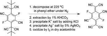 | ||
| Scheme 1 Synthesis of F2-HCNQ. | ||
Fig. 1 compares the absorption spectra of F2-HCNQ and F4-TCNQ along with their cyclic voltammograms (CVs) as depicted in the inset. The shape of the optical absorption of F2-HCNQ (peak at 403 nm) is very similar to that of F4-TCNQ (peak at 391 nm), and both show a pronounced shoulder on the short wavelength side (located at 379 nm and 371 nm, respectively). The subtle bathochromic shift observed from F4-TCNQ to F2-HCNQ is expected because of the slightly extended conjugation resulting from replacement of fluorine with cyano.
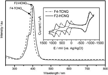 | ||
| Fig. 1 Absorption spectra of F2-HCNQ and F4-TCNQ. Inset: their CV data. | ||
As expected, F2-HCNQ is a much stronger electron acceptor than F4-TCNQ, exhibiting two reversible one-electron reduction waves corresponding to the anion-radicals and dianions. The first reduction potential, determined as the mean values between the cathodic current peak voltages and their corresponding anodic peaks, is 0.87 V for F2-HCNQ and 0.61 V for F4-TCNQ. Based on CV data and optical bandgap (Fig. 1), the lowest unoccupied molecular orbital (LUMO) and the highest occupied molecular orbital (HOMO) energy levels can be estimated according to the relationship: EHOMO/LUMO = Eref−Eox/red, where Eref is the potential of reference to the vacuum level, where for Ag/AgCl, Eref = −4.72 eV; Eox/red refers to oxidation/reduction potential of molecules relative to the reference elctrode used in measurement.19–22 Thus, HOMO/LUMO of F4-TCNQ and F2-HCNQ can be estimated as −8.25/−5.33 eV and −8.39/−5.59 eV, respectively. Our LUMO value for F4-TCNQ (−5.33 eV) by the CV method is quite consistent with that (−5.24 eV) by the ultraviolet photoemission spectroscopy (UPS) method,23 merely differing by 0.09 eV; this indicates the accuracy of our CV measurement. For a p-type dopant/matrix system, doping occurs via charge transfer from the HOMO of the host to the LUMO of the dopant. It will be energetically favorable when there is a close energy match between the host HOMO and the dopant LUMO. It is clear that the choice of host matrix for F2-HCNQ is greater than that for F4-TCNQ because its LUMO at −5.59 eV is significantly larger than that of F4-TCNQ (−5.33 eV). The wider choice of HIM/HTMs for F2-HCNQ can be advantageous in the design of a p-doped organic hole transporting layer in organic optoelectronic devices.
As thermal stability of materials is an essential pre-requisite for a long lifetime of an organic optoelectronic device, the thermal behavior of F2-HCNQ was compared to that of F4-TCNQ by thermal gravimetric analysis (TGA, see ESI†). It reveals that the temperature for 5% weight loss of F4-TCNQ is 256.8 °C, while that for our newly synthesized F2-HCNQ is 372.2 °C, which is over 115 °C higher. The main weakness of F4-TCNQ is its high volatility,13 which makes it difficult to handle as a dopant, and may result in undesirable heterogeneities in the dopant/host layer. Concomitantly, the risk of cross contamination during the fabrication process is also high. Accordingly, the deposition temperatures of F4-TCNQ and F2-HCNQ as a function of deposition rates were studied under the same conditions; the results are shown in Fig. 2. Consistent with the TGA results, the deposition temperatures of F2-HCNQ are higher, in the range of 187 to 212 °C when the deposition rate increases from 0.01 to 0.05 Å s−1. Those of F4-TCNQ are in the range of 131 to 154 °C. It is evident that F2-HCNQ is much more thermally tolerant than F4-TCNQ. Hence, the disadvantages of F4-TCNQ as a p-type dopant, such as difficult control of evaporation rate and manufacturing process, chamber pollution as well as an undesirable aging effect are expected to be avoided by using F2-HCNQ.
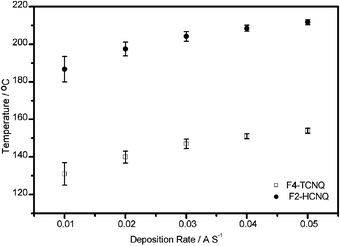 | ||
| Fig. 2 Deposition temperature of F2-HCNQ and F4-TCNQ vs. deposition rate. | ||
For the study of hole-injection and transporting ability of F2-HCNQ doped HIM/HTM films, as well as to demonstrate the advantages of these films, three types of hole only devices with the structure of ITO/2-TNATA/Au (Type I), ITO/2-TNATA: 2% F4-TCNQ/Au (Type II), and ITO/2-TNATA: 2% F2-HCNQ/Au (Type III) were fabricated (2-TNATA = 4,4′,4″-tris(N-(2-naphthyl)-N-phenyl-amino)-triphenylamine), as shown in Fig. 3. The thickness of the organic layer and the Au layer in all three types of device is 600 Å and 150 Å respectively. There are three pieces in the device for each type: one piece worked as a control device that was measured immediately after having been freshly prepared; the other two pieces were annealed for one hour under 1 × 10⁻⁶ Torr at two different temperatures of 65 °C and 85 °C, respectively. The I–V characteristics of these samples are shown in Fig. 4. The currents of the F4-TCNQ or F2-HCNQ doped devices are nearly two orders of magnitude larger than those of the corresponding undoped ones. The dramatic enlargement of hole current can be attributed to an increase in film conductivity or in carrier injection via tunneling, or both.24 When the F2-HCNQ doped 2-TNATA devices (Type III) were annealed under vacuum at 65 °C and 85 °C, respectively, the hole currents were found to hold essentially constant, exhibiting very good thermal stability, as shown in Fig. 4 while the Type II device did not. Actually, the hole current of the F4-TCNQ doped 2-TNATA device decreased dramatically after 65 °C annealing under vacuum, which was even worse than the undoped control (inset of Fig. 4). Furthermore, for the Type III device after being stored for 500 h in a desiccator under the conditions of 30% relative humidity and 25 °C, there is no morphology deterioration when observed through an optical microscope. The I–V characteristic remains unchanged (see ESI†), reflecting good quality of the film and excellent stability of the doping system.
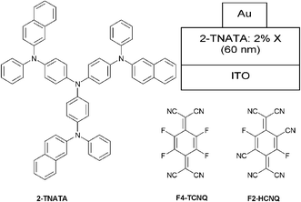 | ||
| Fig. 3 Materials used for p-doped hole only device, and the device structure. Type I: no dopant, Type II: X = F4-TCNQ, Type III: X = F2-HCNQ. | ||
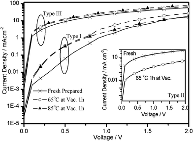 | ||
| Fig. 4 I–V characteristics of 2-TNATA devices doped or undoped with F2-HCNQ with annealing process under vacuum. Inset: I–V of F4-TCNQ doped 2-TNATA devices with or without annealing. | ||
In summary, newly synthesized p-dopant F2-HCNQ has been studied for application as an excellent p-type dopant in an organic optoelectronic device. Compared to the state-of-the-art F4-TCNQ, F2-HCNQ is a stronger electron acceptor which has higher thermal stability and lower volatility. The deposition temperature of F2-HCNQ is much higher than that of F4-TCNQ. A F2-HCNQ doped 2-TNATA layer shows high hole transporting ability up to 85 °C. All these results demonstrate that F2-HCNQ is a promising high temperature p-type dopant material for organic semiconductor application. Based on the preliminary study on F2-HCNQ, we expect that an OLED device with F2-HCNQ as a p-type dopant will have considerably improved performance, such as low driving voltage, long lifetime, high thermal stability.
We are grateful for the support of Hong Kong Innovation and Technology Commission Guangzhou-Hong Kong Industrial Support Grant, ITC/05-06/02 and e-Ray Optoelectronics, Ltd., HK, for providing some of the organic materials for this work.
Notes and references
- D. S. Acker, R. J. Harder, W. R. Hertler, W. Mahler, L. R. Melby, R. E. Benson and W. E. Mochel, J. Am. Chem. Soc., 1960, 82, 6408 CrossRef CAS.
- P. Bando, N. Martin, J. L. Segura, C. Seoane, E. Orti, P. M. Viruela, R. Viruela, A. Albert and F. H. Cano, J. Org. Chem., 1994, 59, 4618 CrossRef CAS.
- S. Hünig and E. Herberth, Chem. Rev., 2004, 104, 5535 CrossRef.
- N. Martin, J. L. Segura and C. Seoane, J. Mater. Chem., 1997, 7, 1661 RSC.
- L. R. Melby, R. J. Harder, W. R. Hertler, W. Mahler, R. E. Benson and W. E. Mochel, J. Am. Chem. Soc., 1962, 84, 3374 CrossRef CAS.
- J. Blochwitz, M. Pfeiffer, T. Fritz and K. Leo, Appl. Phys. Lett., 1998, 73, 729 CrossRef CAS.
- J. Huang, M. Pfeiffer, A. Werner, J. Blochwitz, K. Leo and S. Liu, Appl. Phys. Lett., 2002, 80, 139 CrossRef CAS.
- M. Pfeiffer, K. Leo, X. Zhou, J. S. Huang, M. Hofmann, A. Werner and J. Blochwitz-Nimoth, Org. Electron., 2003, 4, 89 Search PubMed.
- B. Maennig, J. Drechsel, D. Gebeyehu, P. Simon, F. Kozlowski, A. Werner, F. Li, S. Grundmann, S. Sonntag, M. Koch, K. Leo, M. Pfeiffer, H. Hoppe, D. Meissner, N. S. Sariciftci, I. Riedel, V. Dyakonov and J. Parisi, Appl. Phys. A: Mater. Sci. Process., 2004, 79, 1 CrossRef CAS.
- J. Huang, J. Blochwitz-Nimoth, M. Pfeiffer and K. Leo, J. Appl. Phys., 2003, 93, 838 CrossRef CAS.
- Z. Zhou, M. Pfeiffer, J. Blochwitz, A. Werner, A. Nollau, T. Fritz and K. Leo, Appl. Phys. Lett., 2001, 78, 410 CrossRef CAS.
- M. Pfeiffer, A. Beyer, T. Fritz and K. Leo, Appl. Phys. Lett., 1998, 73, 3202 CrossRef CAS.
- J. Drechsel, M. Pfeiffer, X. Zhou, A. Nollau and K. Leo, Synth. Met., 2002, 127, 201 CrossRef CAS.
- P. Wellmann, M. Hofmann, O. Zeika, A. Werner, J. Birnstock, R. Meerheim, G. He, K. Walzer, M. Pfeiffer and K. Leo, Inf. Disp., 2005, 13, 393 Search PubMed.
- C.-C. Chang, M. T. Hsieh, J.-F. Chen, S.-W. Hwang, J.-W. Ma and C. H. Chen, Dig. Tech. Pap. – Soc. Inf. Disp. Int. Symp., 2006, 1106 Search PubMed.
- R. C. Wheland and J. L. Gillson, J. Am. Chem. Soc., 1976, 98, 3916 CrossRef CAS.
- W. J. Lyman, W. F. Reehl and D. H. Rosenblatt, in Handbook of Chemical Property Estimation Methods, McGraw-Hill, New York, 1981, pp. 6-11 to 6-12 Search PubMed.
- B. E. Koene, D. E. Loy and M. E. Thompson, Chem. Mater., 1998, 10, 2235 CrossRef CAS.
- M. R. Andersson, M. Berggren, O. Inganäs, G. Gustafsson, J. C. Gustafsson-Carlberg, D. Selse, T. Hjertberg and O. Wennerström, Macromolecules, 1995, 28, 7525 CrossRef CAS.
- A. K. Agrawal and S. A. Jenekhe, Chem. Mater., 1996, 8, 579 CrossRef CAS.
- I. Seguy, P. Jolinat, P. Destruel, J. Farenc, R. Mamy, H. Bock, J. Ip and T. P. Nguyen, J. Appl. Phys., 2001, 89, 5442 CrossRef CAS.
- B. W. D'Andrade, S. Datta, S. R. Forrest, P. Djurovich, E. Polikarpov and M. E. Thompson, Org. Electron., 2005, 6, 11 Search PubMed.
- W. Gao and A. Kahn, Appl. Phys. Lett., 2001, 79, 4040 CrossRef CAS.
- W. Gao and A. Kahn, Org. Electron., 2002, 3, 53 Search PubMed.
Footnotes |
| † Electronic supplementary information (ESI) available: Synthesis procedures and characterization for F2-HCNQ; devices fabrication details. See DOI: 10.1039/b713566a |
| ‡ Characterization data for F2-HCNQ: mp: 309 °C decomp.; high resolution MS: m/z 290.0159 (M−, theoretical value: 290.0158, error: 0.3448 ppm); Calcd. (C14F2N6), C: 57.95, H: 0, N: 28.96; Found, C: 57.39, N: 28.55, H: 0.564%; FT IR (KBr, cm−1): 2202, 1630 (br), 1462, 1335, 919; UV–vis (CH2Cl2, λ/log ε): 402 nm/4.23. |
| This journal is © The Royal Society of Chemistry 2008 |
