An improved sensitivity non-enzymatic glucose sensor based on a CuO nanowire modified Cu electrode†
Zhenjing
Zhuang
a,
Xiaodong
Su
a,
Hongyan
Yuan
a,
Qun
Sun
b,
Dan
Xiao
*a and
Martin M. F.
Choi
*c
aCollege of Chemical Engineering, Sichuan University, Chengdu 610065, P. R. China. E-mail: xiaodan@scu.edu.cn; Fax: +86 28 8540 7859; Tel: +86 28 8540 7958
bCollege of Life Sciences, Sichuan University, Chengdu 610065, P. R. China
cDepartment of Chemistry, Hong Kong Baptist University, Kowloon Tong, Hong Kong SAR, P.R. China. E-mail: mfchoi@hkbu.edu.hk; Fax: +852 3411 7348; Tel: +852 3411 7839
First published on 5th November 2007
Abstract
CuO nanowires have been prepared and applied for the fabrication of glucose sensors with highly enhanced sensitivity. Cu(OH)2 nanowires were initially synthesised by a simple and fast procedure, CuO nanowires were then formed simply by removing the water through heat treatment. The structures and morphologies of Cu(OH)2 and CuO nanowires were characterised by X-ray diffraction, X-ray photoelectron spectroscopy, scanning electron microscopy, and transmission electron microscopy. The direct electrocatalytic oxidation of glucose in alkaline medium at CuO nanowire modified electrodes has been investigated in detail. Compared to a bare Cu electrode, a substantial decrease in the overvoltage of the glucose oxidation was observed at the CuO nanowire electrodes with oxidation starting at ca. 0.10 V vs.Ag/AgCl (saturated KCl). At an applied potential of 0.33 V, CuO nanowire electrodes produce high and reproducible sensitivity to glucose with 0.49 µA/µmol dm–3. Linear responses were obtained over a concentration range from 0.40 µmol dm–3 to 2.0 mmol dm–3 with a detection limit of 49 nmol dm–3 (S/N = 3). The CuO nanowire modified electrode allows highly sensitive, low working potential, stable, and fast amperometric sensing of glucose, thus is promising for the future development of non-enzymatic glucose sensors.
Introduction
Since reliable and fast monitoring of glucose is important in areas such as biotechnology, clinical diagnostics and the food industry, the development of electrochemical glucose sensors has received continuous interest. Most previous studies on this subject involved the use of the enzyme glucose oxidase,1 which catalyses the oxidation of β-D-glucose to δ-gluconolactone. However, the greatest drawback of enzymatic sensors is their lack of stability due to the intrinsic nature of enzymes. To address this problem, many attempts have been made to determine glucose concentration without using enzymes. The direct electro-oxidation of glucose on different substrates such as platinum,2gold,3 alloys,4copper,5 and electrodes modified with copper,6–8nickel,9bismuth,10silver,11 and mercury12 has been explored in the hope of developing effective enzyme-free sensors. However, most of these electrodes have drawbacks of low sensitivity and poor selectivity caused by surface poisoning from the adsorbed intermediates and chloride.2,3 Hence, it is pertinent to explore and develop a non-enzymatic sensor with high sensitivity, fast response time, and stability for the determination of glucose by electrochemical oxidation.In recent years, nanomaterials with special physical and chemical properties have been widely applied in chemosensors and biosensors. Chemosensors or biosensors modified with metallic nanoparticles show good performances through increasing the surface area and enhancing the mass transport and catalysis. Therefore, it is an important strategy in the construction of a glucose non-enzymatic sensor with nanomaterials. For instance, nanotubular array Pt electrodes possess high sensitivity and selectivity due to their high surface-roughness factor and particular structure.13Glucose detection using mesoporous Pt has been reported and the mesoporous surface retains sufficient sensitivity in the presence of chloride.14 Ni nanoparticles,15Au nanoparticles,16,17Pt nanoparticles,18,19Pt/Pb nanoparticles20 and carbon nanotube21,22 modified electrodes have also been developed to fabricate glucose sensors. Glucose sensors based on nanomaterial electrodes are growing continuously. Recently there have been a few attempts to amperometrically detect glucose using Cu nanoparticles or CuO/Cu(OH)2 nanoparticles. For example, functionalised Cu nanoparticles with organic shells demonstrated an improved stability in glucose determination.23,24Electrodes based on carbon nanotubes and Cu nanoparticles have also shown good electrocatalytic activity towards the oxidation of glucose in an alkaline medium.25,26
It is well-known that Cu nanomaterials are unstable for electroanalysis due to their ease of oxidisation in air and solution.23–26 In contrast, CuO nanomaterials are relatively stable and have been used for glucose detection. You et al. dispersed CuO/Cu(OH)2 nanoparticles into graphite-like carbon films by an RF sputtering method.27 The resulting glucose sensor had enhanced sensitivity and stability. In this work, we report a new method to directly grow CuO nanowires on a Cu substrate. This method also involves a mild, template-free, aqueous route to fabricate Cu(OH)2 nanowires on a Cu surface. Through further heat treatment at 120–180 °C, the facile transformation of Cu(OH)2 to CuO nanowires without obvious morphological changes has been achieved. This process of fabricating CuO nanowires is simple without using complicated and expensive equipment. Our CuO nanowires grown on the Cu substrate with a large coverage are very stable. It can be used directly as an electrochemical sensor. The present research demonstrates that a glucose sensor based on CuO nanowires provides better sensitivity, stability, a lower detection limit and faster current response than those of the other reported methods. In addition, our proposed sensor also offers good selectivity, long-term stability, and immunity to chloride poisoning.
Experimental
Materials
Acetone, CuSO4·5H2O, NaOH, and Na2O2, were obtained from Chengdu Chemical Reagent Factory (Chengdu, China). Ascorbic acid, fructose, D-galactose, glucose, lactose, maltose, D-mannose, sucrose, and uric acid were purchased from Guoyao Chemical Reagent Factory (Shanghai, China). High-purity copper foils (Cu, 99.999%) were from Shanghai Chemical Reagent Co. (Shanghai, China). Copper rods (Cu, 99.9%) were purchased from Shanghai Jiaxi Copper Factory (Shanghai, China). All reagents were all of analytical grade or above. All solutions were freshly prepared with doubly distilled water (DDW).Fabrication of Cu(OH)2 nanowires
Cu(OH)2 nanowires were fabricated by mixing 1.0 cm3 of 7.5 mmol dm–3 CuSO4 aqueous solution with 1.0 cm3 of 80 mmol dm–3 Na2O2 aqueous solution for 20 min at room temperature. The Cu(OH)2 nanowire precipitates were cleaned by copious amounts of DDWvia several centrifugation and redispersion cycles. The Cu(OH)2 nanowires were used for taking transmission electron micrographs.Synthesis of Cu(OH)2 nanowires on a Cu substrate
A typical synthesis of Cu(OH)2 nanowires on a copper substrate was carried out as follows. First, a Cu foil was cleaned by an abrasive paper, and then washed with DDW three times to remove surface impurities. The carefully cleaned Cu foil was immersed into 10 cm3 of a 7.5 mmol dm–3 CuSO4 aqueous solution, then 10 cm3 of 0.4 mol dm–3 Na2O2 was added. After 20 min, a blue layer was formed on the surface of the foil. Finally, the Cu foil coated with the product layer was taken out, washed with DDW three times, and dried in air for further characterisation.Transformation of Cu(OH)2 nanowires to CuO nanowires on the Cu substrate
Cu rods with diameters of 5.0 mm were used as the Cu substrate. The Cu rods were cleaned in acetone for 10 min and rinsed in DDW. Afterwards, one end of the Cu rod was polished with an abrasive paper, rinsed with DDW, and dried with a filter paper. Then the clean end of the rod was used for the growth of Cu(OH)2 nanowires as described above. The Cu rod with Cu(OH)2 nanowires was put into a ceramic crucible and placed into a muffle furnace. The sample was heated at 120 °C for 3 h to dehydrate the Cu(OH)2. After that, the temperature was raised to 180 °C and maintained for 3 h to promote crystallisation. Finally, the sample was cooled to room temperature and a dark brown layer of CuO nanowires was formed on the surface of the Cu rod.Construction of working electrode
The working electrode was made in-house by sealing the CuO nanowire modified Cu rod with a Teflon holder. The CuO nanowire modified Cu rod was sealed tightly and pressed to fit so that only a circular plane (geometric area 0.20 cm2) of the CuO nanowire layer was exposed. Prior to use, the CuO nanowire modified electrode was cleaned with copious amounts of DDW. For comparison, an unmodified Cu electrode was also prepared similarly.Instrumentation
Samples for transmission electron microscopy (TEM) were prepared by placing a drop of precipitate on a carbon-coated copper grid and allowing it to dry in air. TEM measurements were conducted on a Philips Tecnai 20 TEM (Amsterdam, The Netherlands) operating at 200 kV. CuO and Cu(OH)2 nanowires on the Cu substrates were used directly for X-ray diffraction (XRD) and scanning electron microscope (SEM) measurements. XRD analysis was performed on a DX-1000 powder X-ray diffractometer (Dandong Fangyuan Instrument Co., Dandong, China) with Cu Kα radiation. The morphologies of Cu(OH)2 nanowires were characterised using a JEOL 5900 SEM (Tokyo, Japan) operating at 15 kV. The SEM image of CuO nanowires was performed on a Hitachi 4800 SEM (Tokyo, Japan) operating at 5 kV. The X-ray photoelectron spectra (XPS) were acquired with a Thermo VG Scientific ESCALab 250 XPS spectrometer (Waltham, MA, USA) equipped with an Mg K X-ray (1253.6 eV) excitation source running at 15 kV, a hemispherical electron energy analyser, and a multichannel detector. The high sensitivity of this instrument at a routine instrumental energy resolution of 0.5 eV fwhm at a 30 eV pass energy allowed us to characterise spectral features of CuO nanowires on the Cu surface.Electrochemical measurements
Electrochemical measurements were performed on an Autolab PGSTAT 12 potentiostat (Amsterdam, The Netherlands). All electrochemical experiments were carried out using a conventional three-electrode system consisting of an Ag/AgCl (saturated KCl) reference electrode, a platinum foil counter electrode, and a CuO nanowire modified Cu working electrode. A magnetic stirrer and a stirring bar provided convective mass transport. A 0.15 mol dm–3NaOH solution was used as the supporting electrolyte.Results and discussion
1. Synthesis of Cu(OH)2 nanowires
It is well-known that orthorhombic Cu(OH)2 can be easily transformed to monoclinic CuO by heat treatment. The thermal dehydration of one-dimensional (1D) Cu(OH)2 nanostructures to 1D CuO nanostructures has been well-documented.28–32 Since Cu(OH)2 served as the precursor and can be easily transformed to CuO, the assembly of Cu(OH)2 nanowires and their growth on the Cu surface has been widely investigated. Recently, various approaches were developed for the fabrication of 1D Cu(OH)2 nanostructures;33–39 however, they either needed special instruments or the synthesis time was long. Here, we propose a simple and rapid approach for solution-phase synthesis of Cu(OH)2 nanowires using Na2O2 aqueous solution as the OH– source.Direct observation of the morphology of the as-prepared samples was achieved by SEM. Fig. 1A visualises the morphology of Cu(OH)2 on a Cu surface. Cu(OH)2 nanowires with diameters of about 30 nm form a wheat-like structure directly on the Cu surface. The wheat-like Cu(OH)2 morphology comprises entirely of nanowires which bundle up to several hundreds of nanometers in diameter as depicted in the inset of Fig. 1A. The XRD pattern of the as-prepared sample on the Cu surface (Fig. 1B) is attributed to the orthorhombic Cu(OH)2 phase. In Fig. 1B, all the diffraction peaks arising from the Cu substrate, except those marked with an asterisk, can be indexed to this phase. Compared with the standard diffraction patterns (JCPDS Card No. 13-0420), no characteristic peaks from impurities are detected; therefore, pure Cu(OH)2 nanowires have been successfully grown on the Cu surface.
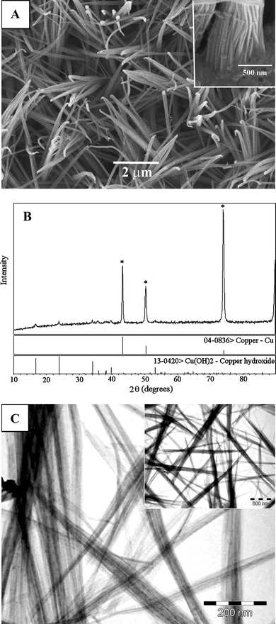 | ||
| Fig. 1 (A) SEM image of Cu(OH)2 nanowires grown on the Cu surface. Inset: the morphology of wheat-like Cu(OH)2 nanowires at the bottom. (B) XRD pattern of Cu(OH)2 samples. (C) TEM image of Cu(OH)2 nanowires. Scale bars: (A) 2 µm and inset 500 nm, and (C) 200 nm and inset 500 nm. | ||
The reaction that accounts for the growth of Cu(OH)2 nanowires is essentially an oxidation process,
| Cu + Na2O2 + 2H2O → Cu(OH)2 + 2NaOH |
| 2Na2O2 + 2CuSO4 + 2H2O → 2Cu(OH)2 + O2↑ + 2Na2SO4 |
2. Characterisation of CuO nanowires
CuO nanowires were obtained from Cu(OH)2 nanowires by heat treatment in air. A relatively low temperature (120 °C) is used to retain the wire morphology. As shown in Fig. 2, the wire-like morphology of CuO is well-preserved. The SEM image (Fig. 2A) indicates that bundles of CuO nanowires with diameters of about 50 nm stemmed from the Cu surface. The CuO nanowires appear to be more densely packed as compared to the original Cu(OH)2 nanowires, probably attributing to better crystallisation of CuO through thermal dehydration. XPS is a powerful technique for the study of transition metal compounds having localized valence d-orbitals. The XPS detected the Cu 2p3/2 and Cu 2p1/2 at 932.8 and 952.4 eV, respectively (shown in Fig. S3†). The peak-fit of Cu 2p3/2 revealed a main peak at 932.8 eV and was accompanied by a series of satellites on the high binding energy sides, 934.2, 940.9, and 943.5 eV. The main peak is known as the characteristic of Cu+ and the shake-up satellite peaks are evident and diagnostic of an open 3d9 shell, corresponding to the Cu2+ state. The relative intensities of the shake-up satellites from these levels indicate the presence of CuO at the surface.42 The XPS result, together with the XRD pattern in Fig. 2B, confirms that the Cu(OH)2 nanowires have been completely converted to CuO nanowires on the Cu substrate surface.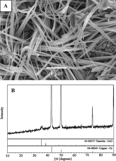 | ||
| Fig. 2 (A) SEM images of CuO nanowires. Scale bars: 1 µm. (B) XRD of CuO nanowires on the Cu surface. | ||
3. Electrocatalysis of glucose at the CuO nanowire modified electrode
The electrocatalytic activity of the CuO nanowire modified electrode towards the oxidation of glucose in an alkaline solution was demonstrated first of all. Fig. 3 displays the cyclic voltammograms (CVs) of 1.0 mmol dm–3glucose in 0.15 mol dm–3NaOH at the CuO nanowire modified and bare Cu electrodes respectively. In the alkaline solution, a single somewhat broad reduction with a peak potential of about 0.53 V vs.Ag/AgCl was observed at both electrodes. This wave might correspond to a Cu(II)/Cu(III) redox couple similar to the previous reports.6,7,23,43 Upon addition of 1.0 mmol dm–3glucose, a single forward oxidative wave, corresponding to the irreversible glucose oxidation, was observed for both electrodes. For the CuO nanowire modified electrode, however, a substantial negative shift of the anodic peak potential and dramatic increase of current signal were observed as depicted in Fig. 3A (dashed curve). The oxidation process starts at approximately 0.10 V vs.Ag/AgCl, and the current continues to increase to a potential of about 0.45 V vs.Ag/AgCl. This may be attributed to the proposed involvement of Cu(II) and Cu(III) surface species in the oxidation of glucose although the exact mechanism for the oxidation of glucose in alkaline medium at the Cu-based modified electrode is still not clearly known.7,25,43 The Cu electrode shows a peak oxidation wave at approximately 0.47 V vs.Ag/AgCl while the CuO nanowire modified Cu electrode displays an oxidation peak centred at approximately 0.33 V vs.Ag/AgCl. The obvious decrease in the anodic overpotential to 0.33 V shows a strong catalytic function of the CuO nanowires in the direct oxidation of glucose. The shifts in this overpotential may be due to a kinetic effect by an increase in the electroactive surface area and the rate of electron transfer from glucose to the CuO nanowire modified Cu electrode. Furthermore, the CVs of glucose solution at different scan rates were recorded as depicted in Fig. 4. The peak current for the anodic oxidation of glucose is proportional to the square root of the scan rate, indicating that the electrocatalytic reaction is diffusion controlled, which is ideal for quantitative analysis in practical applications.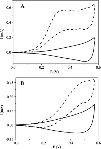 | ||
| Fig. 3 Cyclic voltammograms (CVs) of 1.0 mmol dm–3glucose in 0.15 mol dm–3NaOH at the (A) CuO nanowire modified and (B) bare Cu electrodes. Solid and dashed curves represent the CVs without and with glucose, respectively. The scan rate is 100 mV s–1. | ||
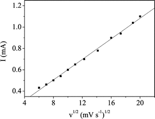 | ||
| Fig. 4 Peak current as a function of sweep rate at the CuO nanowire modified electrode subject to 1.0 mmol dm–3glucose in 0.15 mol dm–3NaOH. | ||
In order to improve its performance, various factors affecting the response of the sensor were investigated such as the concentration of NaOH and the applied potential used. The effect of NaOH concentration on the response of glucose was investigated by CV measurement. The concentrations of NaOH used are 0.012, 0.80, 0.15, and 0.50 mol dm–3. The peak current of 1.0 mmol dm–3glucose at 0.33 V vs.Ag/AgCl was increased with the concentration of NaOH until it reached 0.15 mol dm–3 (ionic strength is 0.15) and then decreased with the further increase in NaOH. The optimal value of the applied potential was obtained by amperometric measurement of glucose concentration in 0.15 mol dm–3NaOH at applied potentials of 0.28, 0.33, 0.38, and 0.42 V. The sensitivity of the sensor at different applied potentials is shown in the ESI† in Table S1. The results demonstrated that the maximum response sensitivity was obtained at 0.33 V vs.Ag/AgCl. As such, 0.15 mol dm–3NaOH and an applied potential of 0.33 V were chosen for subsequent experiments.
Fig. 5 displays a typical amperometric response curve of glucose in 0.15 mol dm–3NaOH at the CuO nanowire modified electrode. A well-defined, stable and fast amperometric response could be observed at 0.33 V with successive additions of glucose into 0.15 mol dm–3NaOH. The time required to reach the stable response was less than 1 s, which is much faster than the other glucose sensors.3,18,24,25 The calibration curve for the glucose sensor is shown in the bottom inset of Fig. 5. The sensor displays a linear range for 0.40 µmol dm–3 to 2.0 mmol dm–3glucose with a correlation coefficient of 0.999, a sensitivity of 0.49 µA/µmol dm–3, and a detection limit of 49 nmol dm–3 with a signal/noise ratio of 3. The sensitivity of our CuO nanowire modified electrode is compared with other non-enzymatic glucose sensors as summarised in Fig. 6. It is clear that the sensitivity of our present non-enzymatic glucose sensor is largely improved. All the data from this sensor reveal the properties of high sensitivity, low detection limit and fast response time, attributed to the fact that CuO nanowires can greatly increase the electrocatalytic active areas and promote electron transfer in the oxidation of glucose.
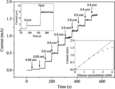 | ||
| Fig. 5 Steady-state current–time responses of glucose at the CuO nanowire modified electrode at 0.33 V subject to various concentrations of glucose in 0.15 mol dm–3NaOH. Top inset displays the response to 0.40 and 10 µmol dm–3glucose. Bottom inset shows the calibration curve of glucose. | ||
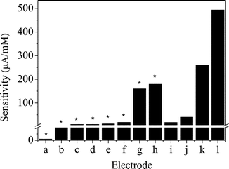 | ||
| Fig. 6 Comparison of the sensitivity of various non-enzymatic glucose sensors. The units of those marked with an asterisk are µA/cm–2 mM–1. (a) Pt-nanotube arrays electrode,13 (b) multi-walled carbon nanotube modified electrode,21 (c) mesoporous Pt electrode,14 (d) macroporous Pt electrode,19 (e) porous Au electrode,3 (f) Pt/Pb alloy nanoparticle/carbon nanotube nanocomposites,20 (g) Au nanoparticles,16 (h) Au nanoparticles,17 (i) Cu nanoparticle and carbon nanotube modified electrode,25 (j) Ni powder modified electrode,9 (k) Cu nanocluster/multi-wall carbon nanotube modified electrode,26 and (l) our proposed CuO nanowire modified electrode. | ||
The reproducibility and stability of the sensor was evaluated. Three CuO nanowire modified electrodes were made and their current responses to 1.0 mmol dm–3glucose at 0.33 V were investigated. The relative standard deviation (RSD) was 2.31%, confirming that the fabrication method was highly reproducible. Three successive measurements of 1.0 mmol dm–3glucose on one CuO nanowire modified electrode yielded an RSD of 3.46%, demonstrating that the sensor was stable. The electrodes were not poisoned by the oxidation product and can be used repeatedly for the detection of glucose. The long-term stability of the sensor was evaluated by measuring its sensitivity to glucose within a 50 day period. The sensor was stored in air at ambient conditions and its sensitivity was tested every 10 days. The result demonstrated that the sensitivity was 94% of its initial sensitivity after being stored for 50 days. The good reproducibility and long-term stability of the sensor are desirable for most routine analysis.
It has been reported that electrochemical glucose sensors based on Cu electrodes can easily lose their activity due to the chloride poisoning effect. Thus, the amperometric response was examined by adding the supporting electrolyte with chloride (i.e. replacing 0.15 mol dm–3NaOH with 0.050 mol dm–3KCl in 0.15 mol dm–3NaOH). The linear response for glucose at the CuO nanowire modified electrode remains almost constant (data not shown), implying that the electrode can be used as a glucose sensor in the presence of chloride.
Easily oxidisable species such as ascorbic acid (AA) and uric acid (UA) normally co-exist with glucose in real samples. The normal physiological level of glucose is 3–8 mmol dm–3 and the interfering species are about 0.1 mmol dm–3. Since the interfering species have higher electron transfer rates than glucose, their oxidation currents will be comparable to glucose. Moreover, the determination of glucose will also be affected by other carbohydrate compounds. Therefore, interference tests were carried out by adding 1.0 mmol dm–3glucose, followed with additions of 0.10 mmol dm–3UA, 0.050 mmol dm–3AA, 0.050 mmol dm–3fructose, 0.050 mmol dm–3sucrose, 0.050 mmol dm–3maltose, 0.050 mmol dm–3mannose, 0.050 mmol dm–3lactose, and finally 0.050 mmol dm–3galactose in 0.15 mol dm–3NaOH. The results shown in Table 1 demonstrate almost negligible interferences from UA, AA, fructose, sucrose, maltose, mannose, lactose, and galactose.
| Interferent | Response current/µA | % Response with respect to glucosea |
|---|---|---|
| a The response to 1.0 mmol dm–3glucose was 491.7 µA. | ||
| Ascorbic acid (0.050 mmol dm–3) | 6.82 | 1.39 |
| Uric acid (0.10 mmol dm–3) | 5.50 | 1.12 |
| Fructose (0.050 mmol dm–3) | 11.92 | 2.42 |
| Sucrose (0.050 mmol dm–3) | 15.83 | 3.22 |
| Maltose (0.050 mmol dm–3) | 8.84 | 1.80 |
| Mannose (0.050 mmol dm–3) | 7.18 | 1.46 |
| Lactose (0.050 mmol dm–3) | 13.52 | 2.75 |
| Galactose (0.050 mmol dm–3) | 9.81 | 2.00 |
Finally, to verify its workability, the sensor was applied to the determination of glucose in real blood serum samples. Here 0.40 cm3 of serum sample was added to 10 cm3 of 0.15 mol dm–3NaOH solution, and the current response was recorded at 0.33 V. Table 2 displays the results of these blood glucose determinations. The data from the proposed glucose sensor are in good agreement with the results from a spectrophotometric method performed in a local hospital.
Conclusion
We have successfully synthesised Cu(OH)2 nanowires on the Cu surface by a simple, rapid and mass-producible method. The conversion of Cu(OH)2 nanowires to CuO nanowires by a heating process has been demonstrated. The morphology of the CuO nanowires is well-preserved after the dehydration of Cu(OH)2 nanowires. The CuO nanowires are then used to construct a non-enzymatic glucose sensor. The newly developed non-enzymatic glucose sensor presents a number of attractive analytical features such as high sensitivity, good stability, reproducibility, and selectivity as well as fast response time. The CuO nanowire modified Cu electrode is easily fabricated and can be used as an amperometric sensor for routine analysis of glucose in real blood serum samples.Acknowledgements
This work is supported by the National Natural Science Foundation of China (Grant No. 20570542) and Education Ministry of China (No. 105141). The authors would like to express our their sincere thanks to Professor R. L. Zhuo of Chongqing University for taking the TEM images, and Sichuan University Affiliated Wangjiang Hospital for donating the blood serum samples and performing the blood glucose test.References
- N. Zhang, T. Wilkop, S. Lee and Q. Cheng, Analyst, 2007, 132, 164 RSC.
- Y. B. Vassilyev, O. A. Khazova and N. N. Nikolaeva, J. Electroanal. Chem., 1985, 196, 105 CrossRef.
- Y. Li, Y.-Y. Song, C. Yang and X.-H. Xia, Electrochem. Commun., 2007, 9, 981 CrossRef CAS.
- Y. Sun, H. Buck and T. E. Mallouk, Anal. Chem., 2001, 73, 1599 CrossRef CAS.
- P. Luo, F. Zhang and R. P. Baldwin, Anal. Chim. Acta, 1991, 244, 169 CrossRef CAS.
- I. G. Casella, M. Gatta, M. R. Guascito and T. R. I. Cataldi, Anal. Chim. Acta, 1997, 357, 63 CrossRef CAS.
- S. T. Farrell and C. B. Breslin, Electrochim. Acta, 2004, 49, 4497 CrossRef CAS.
- J. Zhao, F. Wang, J. Yu and S. Hu, Talanta, 2006, 70, 449 CrossRef CAS.
- A. Salimi and M. Roushani, Electrochem. Commun., 2005, 7, 879 CrossRef CAS.
- G. Wittstock, A. Strübing, R. Szargan and G. Werner, J. Electroanal. Chem., 1998, 444, 61 CrossRef CAS.
- S. B. Aoun, G. S. Bang, T. Koga, Y. Nonaka, T. Sotomura and I. Taniguchi, Electrochem. Commun., 2003, 5, 317 CrossRef CAS.
- F. Matsumoto, M. Harad, N. Koura and S. Uesugi, Electrochem. Commun., 2003, 5, 42 CrossRef CAS.
- J. Yuan, K. Wang and X. Xia, Adv. Funct. Mater., 2005, 15, 803 CrossRef CAS.
- S. Park, T. D. Chung and H. C. Kim, Anal. Chem., 2003, 75, 3046 CrossRef CAS.
- T. You, O. Niwa, Z. Chen, K. Hayashi, M. Tomita and S. Hirono, Anal. Chem., 2003, 75, 5191 CrossRef CAS.
- F. Kurniawan, V. Tsakova and V. M. Mirskya, Electroanalysis, 2006, 18, 1937 CrossRef CAS.
- B. K. Jena and C. R. Raj, Chem.–Eur. J., 2006, 12, 2702 CrossRef CAS.
- L.-Q. Rong, C. Yang, Q.-Y. Qian and X.-H. Xia, Talanta, 2007, 72, 819 CrossRef CAS.
- Y.-Y. Song, D. Zhang, W. Gao and X.-H. Xia, Chem.–Eur. J., 2005, 11, 2177 CrossRef CAS.
- H.-F. Cui, J.-S. Ye, W.-D. Zhang, C.-M. Li, J. H. T. Luong and F.-S. Sheu, Anal. Chim. Acta, 2007, 594, 175 CrossRef CAS.
- J.-S. Ye, Y. Wen, W. D. Zhang, L. M. Gan, G. Q. Xu and F.-S. Sheu, Electrochem. Commun., 2004, 6, 66 CrossRef CAS.
- R. P. Deo and J. Wang, Electrochem. Commun., 2004, 6, 284 CrossRef CAS.
- Q. Xu, Y. Zhao, J. Z. Xu and J.-J. Zhu, Sens. Actuators, B, 2006, 114, 379 CrossRef.
- H. Liu, X. Su, X. Tian, Z. Huang, W. Song and J. Zhao, Electroanalysis, 2006, 18, 2055 CrossRef CAS.
- X. Kang, Z. Mai, X. Zou, P. Cai and J. Mo, Anal. Biochem., 2007, 363, 143 CrossRef CAS.
- K. B. Male, S. Hrapovic, Y. Liu, D. Wang and J. H. T. Luong, Anal. Chim. Acta, 2004, 516, 35 CrossRef.
- T. You, O. Niwa, Z. Chen, K. Hayashi, M. Tomita and S. Hirono, Electrochem. Commun., 2002, 4, 468 CrossRef CAS.
- H. Hou, Y. Xie and O. Li, Cryst. Growth Des., 2005, 5, 201 CrossRef CAS.
- X. Wen, W. Zhang and S. Yang, Langmuir, 2003, 19, 5898 CrossRef CAS.
- X. Wen, Y. Xie, C. L. Choi, K. C. Wan, X.-Y. Li and S. Yang, Langmuir, 2005, 21, 4729 CrossRef CAS.
- Z. L. Wang, X. Y. Kong, X. Wen and S. Yang, J. Phys. Chem. B, 2003, 107, 8275 CrossRef CAS.
- W. Wang, O. K. Varghese, C. Ruan, M. Paulose and C. A. Grimesa, J. Mater. Res., 2003, 18, 2756 CrossRef CAS.
- S.-H. Park and H. J. Kim, J. Am. Chem. Soc., 2004, 126, 14368 CrossRef CAS.
- W. Zhang, X. Wen, S. Yang, T. Berta and Z. L. Wang, Adv. Mater., 2003, 15, 822 CrossRef CAS.
- X. Wen, W. Zhang, S. Yang, Z. R. Dai and Z. L. Wang, Nano Lett., 2002, 2, 1397 CrossRef CAS.
- C. Lu, L. Qi, J. Yang, D. Zhang, N. Wu and J. Ma, J. Phys. Chem. B, 2004, 108, 17825 CrossRef CAS.
- X. Song, S. Sun, W. Zhang, H. Yu and W. Fan, J. Phys. Chem. B, 2004, 108, 5200 CrossRef CAS.
- X. Wu, H. Bai, J. Zhang, F. Chen and G. Shi, J. Phys. Chem. B, 2005, 109, 22836 CrossRef CAS.
- Y.-H. Luo, J. Huang, J. Jin, X. Peng, W. Schmitt and I. Ichinose, Chem. Mater., 2006, 18, 1795 CrossRef CAS.
- Z. Zhuang, X. Su, B. Zheng, H. Yuan, Q. Sun and D. Xiao, Sensor Lett. Search PubMed , in press.
- Q. Tang, W. Zhou, J. Shen, W. Zhang, L. Kong and Y. Qian, Chem. Commun., 2004, 712 RSC.
- M. Yin, C.-K. Wu, Y. Lou, C. Burda, J. T. Koberstein, Y. Zhu and S. O'Brien, J. Am. Chem. Soc., 2005, 127, 9506 CrossRef CAS.
- L. D. Burke, G. M. Bruton and J. A. Collins, Electrtrochim. Acta, 1998, 44, 1467 Search PubMed.
Footnote |
| † Electronic supplementary information (ESI) available: SEM images, photographs and XPS spectra of synthesised nanowires and data for the sensitivity of the sensor at different applied potentials. See DOI: 10.1039/b712970j |
| This journal is © The Royal Society of Chemistry 2008 |