Fluid mixing in planar spiral microchannels
Arjun P. Sudarsan and Victor M. Ugaz*
Department of Chemical Engineering, Texas A&M University, College Station, Texas 77843-3122, USA. E-mail: ugaz@tamu.edu; Fax: +1 (979) 845-6446; Tel: +1 (979) 458-1002
First published on 10th November 2005
Abstract
Mixing of fluids at the microscale poses a variety of challenges, many of which arise from the fact that molecular diffusion is the dominant transport mechanism in the laminar flow regime. While considerable progress has been made toward developing strategies to achieve improved mixing in microfluidic systems, many of these techniques introduce additional complexity to device fabrication and/or operation processes. In this work, we explore the use of compact spiral-shaped flow geometries designed to achieve efficient mixing in a format that can be constructed using a single planar soft lithography step without the need for multilayer alignment. A series of 150 µm-wide by 29 µm-tall channels were constructed, each of which incorporated a series of spiral shaped sections arrayed along the flow path. Five spiral designs with varying channel lengths were investigated, and mixing studies were carried out at flow rates corresponding to Reynolds numbers ranging from 0.02 to 18.6. Under appropriate conditions, transverse Dean flows are induced that augment diffusive transport and promote enhanced mixing in considerably shorter downstream distances as compared with conventional planar straight channel designs. Mixing efficiency can be further enhanced by incorporating expansion vortex effects via abrupt changes in cross-sectional area along the flow path.
Introduction
Microfluidics is becoming an increasingly important and mainstream technology in many chemical and biological process and analysis applications.1–12 The potential to replace large-scale conventional laboratory instrumentation with miniaturized and self-contained systems offers a variety of advantages that include reduced hardware costs, low reagent consumption, faster analysis speeds, and the capability of operating in a massively parallel scale in order to achieve high-throughput. For this technology to be successfully employed in µTAS (Micro Total Analysis Systems) research, the ability to rapidly mix two or more reagent streams in a small device footprint is required.2,3,9,12–14Typically, flow in micro-scale conduits is laminar with Reynolds numbers well below the threshold for turbulence (Re = Vd/v < 100, where V is the average flow velocity, d is the characteristic cross-sectional channel dimension and v is the kinematic viscosity of the fluid), leaving molecular diffusion as the predominant driving force for mixing to occur. Furthermore, values of the Péclet number are relatively high in microchannels (Pe = Vd/Dmol > 100, where Dmol is the molecular diffusivity), indicating that diffusive mixing occurs at a much slower rate than the timescales associated with fluid motion. These factors combine to produce characteristic mixing lengths (Δym ∼ V × (d2/D) = Pe × d) on the order of several centimeters, resulting in the need to employ cumbersomely long channels in order to achieve complete mixing. As a consequence of these limitations, considerable effort has been directed toward the development of strategies to achieve rapid laminar flow mixing in microfluidic systems.15–17
In general, mixing strategies can be classified as either active or passive, depending on the operational mechanism. Active mixers employ external forces, beyond the energy associated with the flow, in order to perform mixing. Some examples of techniques developed to accomplish this include electro-osmosis,18 magnetic stirring,19 bubble-induced acoustic actuation20 and ultrasonic effects.21 While generally effective, these designs are often not easy to integrate with other microfluidic components and typically add substantial complexity to the fabrication process. Moreover, since high electric fields, mechanical shearing, or generation of nontrivial amounts of heat are involved, they are not well suited for use with sensitive species (e.g., biological samples).
Passive mixers, on the other hand, avoid these problems by exploiting characteristics of specific flow fields to mix species without application of external electrical or mechanical forces. These designs are also often more straightforward to build and interface with other components. Passive micromixers can be broadly sub-classified into designs based on lamination and rotation techniques. Lamination-based mixers rely on the concept of repeated inter-layering of multiple parallel streams (a so-called split-and-recombine effect) in order to increase the interfacial area between species and accelerate the overall diffusive transport process. Both serial and parallel variations of these mixers have been investigated. Bessoth et al.22 demonstrated parallel lamination by splitting two species into sixteen streams on opposite sides of a silicon wafer, then bringing them together as alternating lamellae in a central zone where diffusive mixing occurred. The idea of serial lamination mixing, where the streams to be mixed are separated from a common inlet channel, was suggested in early work by Schwesinger et al.23 and Branebjerg et al.24 Usually, the streams are first directed in a horizontal conduit after which one or both of the streams are twisted vertically to initiate separation, followed by a sequence of turns to finally rejoin the fluids and create alternating lamellae. In reality however, if the fluid is subject to sudden changes in direction, distortion of the laminar profile is likely to occur making it extremely difficult to achieve multiple lamellae possessing identical cross-sectional profiles. In order to minimize these secondary flow effects, Schönfeld et al. have designed a split-and-recombine mixer incorporating minimal channel curvature capable of generating nearly ideal lamellar profiles.25 While these lamination mixers have been highly successful, the complex 3-D flow geometries associated with most of these designs require cumbersome fabrication and assembly steps. Moreover, the footprints occupied by these channels do not always make them conducive for integration into “on-chip” systems.
Passive rotation mixers that are designed to generate transverse flows across the channel cross-section have also been investigated. Johnson et al.26 and Stoock et al.27 have demonstrated this by pattering the floor of a microchannel with oblique grooves to generate lateral flows that repeatedly stretch and fold fluid segments across the channel cross-section. In these designs faster chaotic mixing is achieved at lower Re. Howell et al.28 showed a modification of this basic design, which involves patterning ridges on the top and bottom of the channel. In this mixer, combined transverse flows generated at the top and bottom of the channel contributed to mixing. A 3-D serpentine geometry with recurring “C-shaped” units has been demonstrated by Liu et al.29 The efficiency of this mixer increases with Re due to presence of eddies formed at the channel bends. Kim et al.30 demonstrated a mixer having triangular projections on the channel walls that induce stretching and folding of the fluid segments. A mixer with combined effects of splitting-and-recombining and advection has been realized in a micromixer comprised of a series of “F-shaped” mixing elements.31
Three-dimensional passive rotation using a breakup process has also been shown to be efficient for mixing.32 While this mixer design is effective for Re ranging from 1–50, its efficiency is highest at Re = 10 due to the combined influence of stretching and folding, breakup and diffusion processes. At lower flow rates (Re = 1) stretching and folding of the interface is absent and mixing is breakup and diffusion limited. At higher flow rates (Re = 50) diffusion is absent and fluids are mixed via stretching and folding and breakup processes. Other examples of mixing techniques that have recently been introduced involve self-circulation in a mixing chamber that is efficient at high flow rates (Re ≥ 50),33 an in-plane passive micromixer with modified telsa structures that employed the “Coanda effect” to improve mixing,34 and a mixer based on surface tension in a geometrical mixing chamber.35 Ismagilov et al.3,36 have developed a technique where multiple fluids are mixed by recirculation inside confined liquid droplets that are dispersed in an immiscible liquid. Günther et al.37 have shown that liquids can be mixed by recirculation that is associated with the introduction of a gas phase that forms a segmented gas–liquid slug flow.
Mixing in more complex 3-D flow networks has also been investigated. For example, micro-stereolithography has been used to construct mixing geometries mimicking conventional macroscale static mixers.38 Another example involves construction of 3-D microvascular networks incorporating arrays of square-spiral towers via direct-write assembly.39 The resulting design consisted of square-spiral towers embedded within a 3-D network and promoted fluid mixing through chaotic advection. Mixing efficiency in this case exhibited an exponential dependence on Re. A barrier embedded Kenics micro-mixer that operates using combined stretching/folding and splitting/reorientation processes has also been fabricated using micro-stereolithography.40 Although these mixing designs have proven to be effective, many of their highly intricate 3-D structures require timescales on the order of hours to days to construct, often with expensive specialized equipment.
Transverse Dean flows that arise as a result of centrifugal effects experienced by fluids traveling along a curved trajectory offer the attractive possibility of providing enhanced mixing in an easily fabricated planar 2-D format by simply introducing curvature to the flow path. The magnitude of these effects is characterized by the dimensionless Dean number (κ = δ0.5Re, where δ is the ratio of the channel hydrodynamic radius to the flow path radius of curvature), which expresses the ratio of inertial and centrifugal forces to viscous forces.41 These centrifugal effects induce a secondary flow field characterized by the presence of two counter-rotating vortices located above and below the plane of symmetry of the channel, coinciding with its plane of curvature (Fig. 1). Additional vortex pairs are known to appear at higher Dean numbers, and recent studies have shown that enhanced mixing can occur in these flows.42,43 However, the corresponding Re in these experiments is fairly large (Re ≫ 100) and outside the range of conditions that are realistically achievable in most microfluidic systems.
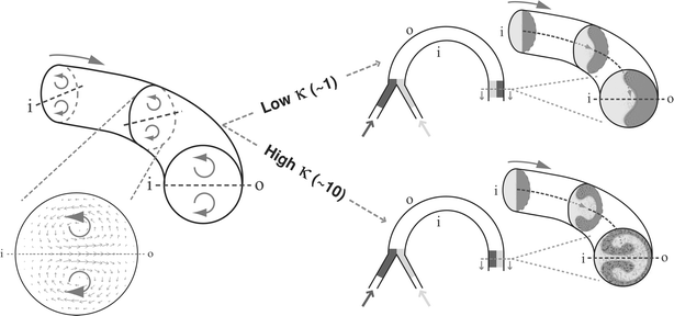 | ||
| Fig. 1 Illustration of Dean flow effects in a curved microchannel (‘i’ and ‘o’ denote the inner and outer channel walls respectively). The transverse flow field is characterized by the presence of two counter-rotating vortices located above and below the channel midplane. At higher κ, the combined action of these vortices cause two fluid streams to almost completely switch positions within the channel. | ||
Dean effects have been investigated to study mixing in serpentine-like microchannels.39,44,45 As fluid flows downstream in a curved channel, centrifugal effects pull the fluid that is closer to the inner wall radially along the midplane towards the outer wall. Simultaneously, fluid that is closer to the outer wall is swept inwards along the channel walls. Ultimately, a nearly complete 180° rotation is induced above and below the midplane that causes the two fluids to almost completely switch positions within the channel (Fig. 1; velocity and concentration profiles were obtained from the analytical solution to a first order perturbation expansion of the equations of motion in a channel of circular cross-section for the ideal case of two immiscible species46). Unfortunately, in serpentine channels that are made up of opposing curved segments, this effect is reversed as the fluids flow from one bend to the other, and this cycle continues along the entire length of the channel. Consequently, the interface between the two fluids simply undulates between the channel walls without achieving appreciable mixing. One way of overcoming this flow reversal problem is to design a channel such that the transverse secondary flows are sustained over longer distances. Howell et al.47 have shown this to be possible in wide (>1 mm) spiral channels and Vanka et al.48 have studied this effect in a 793 µm-wide spiral channel at a flow rate corresponding to Re = 6.8. In such channels the fluid experiences a reduction in the channel radius of curvature as it flows downstream, accompanied by a corresponding increase in the strength of the transverse secondary flow.49
In this work, we present a study of fluid mixing in 150 µm-wide, 29 µm-tall spiral microchannels. Five different designs with varying channel lengths are investigated and flow studies are carried out for a wide range of flow conditions (0.02 ≤ Re ≤ 18.6). Further, we show that by abruptly increasing the cross-sectional area of the channel, expansion vortex effects can be harnessed to rapidly increase the extent of the mixing interface between streams.
Experimental
Master mold and device fabrication
Master molds incorporating spiral structures were fabricated using a previously reported method involving printed circuit technology (Fig. 2A).50 Spiral channels were designed using Adobe Illustrator (Adobe Systems Incorporated; San Jose, CA), and then printed on transparency film with a 3166 dpi printer (Mika Color; Los Angeles, CA) to produce photomasks. PC boards were purchased pre-coated with a positive tone photoresist (1 oz copper foil: Circuit Specialists Inc.; Mesa, AZ) and exposed to UV illumination through the photomask for 90 s (approximate flux 4.5 mW cm−2) to transfer the pattern onto the PC board. Following exposure, the PC boards were immersed for 90–120 s under gentle agitation in a developer solution prepared by mixing 3.5 mL of a 50% w/w aqueous sodium hydroxide solution (Fisher Scientific; Hampton, NH) with 500 mL of deionized water. Next, the PC boards were transferred to a plastic vertical tank containing an etching solution prepared by dissolving 150 g of ammonium peroxydisulfate crystals (certified ACS grade; Fisher Scientific; Hampton, NH) in 1 L of deionized water to etch away the underlying copper foil in the patterned areas. The etching tank was mounted on a hotplate in order to maintain the solution at a temperature of 40–55 °C, and an air pump was used to provide continuous agitation. After the etching process was completed, the remaining photoresist masking the channel structures was stripped with acetone. The height of the channel structures (equivalent to the thickness of the copper foil) was measured to be 29 µm using a stylus profilometer.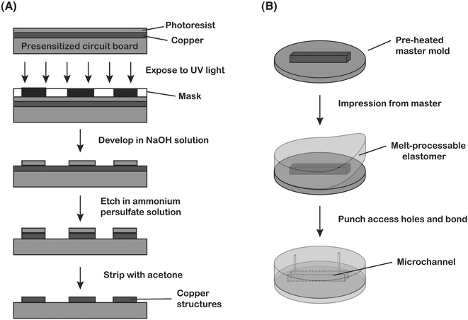 | ||
| Fig. 2 (A) Overview of the printed-circuit board master fabrication process. (B) Soft lithography process for fabrication of planar channels using a melt-processable thermoplastic elastomer from the master molds constructed in (A). | ||
Microfluidic devices were then fabricated using a melt-processable thermoplastic elastomer that was synthesized by combining commercially available polystyrene–(polyethylene/polybutylene)–polystyrene (SEBS) triblock copolymers (e.g. CP-9000, Kraton-G series) in mineral oil (light mineral oil; Fisher Scientific; Hampton, NH).51 Resin and mineral oil (33 wt% copolymer) were mixed and placed under vacuum overnight at room temperature in order to allow the oil to evenly coat the resin surface. The mixture was then heated to 170 °C under vacuum for 4 h to allow the resin and oil to intermix and to remove any residual air pockets. Finally, the mixture was cooled to room temperature and the solidified gel was cut into smaller pieces and placed on top of the PC board master mold that had been preheated to 120 °C on a hot plate (Fig. 2B). Once the elastomer began to soften, a glass plate was placed on top of the slab and gentle pressure was applied by hand to ensure complete contact with the structures on the mold. After cooling and release, the solidified gel incorporates the shape of the structures on the master. Fluidic access holes were made using a syringe needle, and the molded slab was thermally bonded to a flat surface of the elastomer to form enclosed channel networks.
Mixing experiments
Flow studies were carried out by imaging parallel aqueous streams labeled with blue and yellow food dyes (Adams Extract; Austin, TX) diluted to 0.01 g mL−1 of water. Flow rates ranging from 0.0001 to 0.1 mL min−1 (corresponding to Re = 0.02 to 18.6) were controlled using a multi-feed syringe pump (Harvard Apparatus; Holliston, MA). The devices were interfaced with the syringe pump using Teflon tubing (Small Parts Inc.; Miami Lakes, FL). Digital images of the flow were obtained using a MZ 8 microscope (Leica Microsystems Inc.; Bannockburn, IL) interfaced with a Coolpix 4500 digital camera (Nikon). This interface was achieved using a digital camera C-mount coupler (Thales Optem Inc.; Fairport, NY). The extent of mixing was determined by the amount of green color that was generated when the two streams mixed. The digital images were imported into Adobe Photoshop (Adobe Systems Inc., San Jose, CA) where the green color was filtered out and the images were converted to gray-scale and inverted. Mixing intensity was then calculated using the following equation. | (1) |
Results and discussion
Device design
A variety of spiral channels were designed, each incorporating three individual spiral mixing sections connected in series. Each section was composed of an inlet and outlet spiral connected by a central ‘S’-section of length 1.0 mm (Fig. 3A). The inlet and outlet spirals were designed by joining circular arcs whose radius of curvature decayed by 80% every 90°. The longest arc had a radius of curvature of 3.1 mm and the shortest arc had a radius of curvature 420 µm. Spiral sections of five different lengths were designed; the longest incorporated ten arcs on each spiral and the shortest section had two arcs on each spiral (Table 1). Individual spiral sections were connected by straight segments of length 3.0 mm. All spiral channels were 150 µm-wide and 29 µm-tall. Due to the isotropic nature of the etching, channel structures have a trapezoidal cross-section profile (Fig. 3B). The hydraulic diameter of the channel is calculated to be 49 µm and is taken as the characteristic cross-sectional dimension. Fig. 3C shows the Dean numbers along the spiral contours for Re = 0.19 to 18.6. As the radius of curvature decreases, the Dean number increases due to a corresponding increase in the value of δ.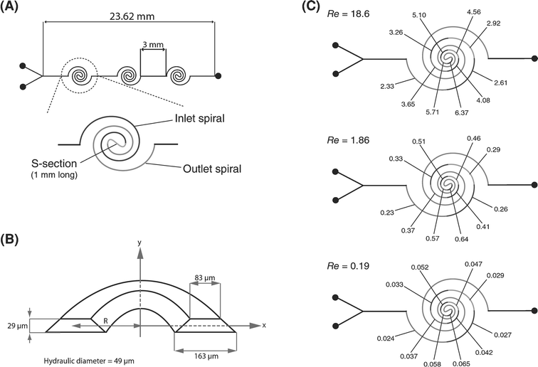 | ||
| Fig. 3 (A) Schematic of the spiral channel network incorporating three mixing sections. Each section consists of an inlet and outlet spiral joined by a central ‘S’-section. (B) Segment of a spiral channel depicting the trapezoidal cross-sectional profile. (C) Dean number along the spiral contour at different Re. | ||
| Spiral design | Arcs on spiral | Max. radius of curvature | Length of inlet/outlet spiral | Length of mixing section | Footprint of mixing section |
|---|---|---|---|---|---|
| a All channels are 29 µm tall. | |||||
| 1 | 2 | 0.52 | 1.47 | 3.97 | 1.2 × 1.0 |
| 2 | 4 | 0.81 | 3.77 | 8.57 | 1.7 × 1.5 |
| 3 | 6 | 1.27 | 7.35 | 15.73 | 2.9 × 2.3 |
| 4 | 8 | 1.98 | 12.96 | 26.95 | 4.4 × 3.6 |
| 5 | 10 | 3.10 | 21.73 | 44.49 | 6.9 × 5.5 |
Mixing in spiral microchannels
In conventional planar straight microchannel geometries, any mixing that occurs is purely by diffusion. In curved channels, transverse secondary Dean flows arise as a result of the interplay between inertial and centrifugal forces. By designing curved channels in spiral formats, the strength of these secondary flows increases as the fluid travels from the outer to the inner regions of the spiral path where the radius of curvature is smallest. Moreover, the direction of rotation of the secondary flows is sustained over the entire length of the spiral, as compared to designs incorporating alternating segments of opposing curvature (e.g., serpentine channels). At low flow rates (Re < 1), the strength of these secondary flows is not sufficient to significantly perturb the laminar flow profile, and mixing between two parallel streams is primarily by diffusion. Nevertheless, since these channels are in a spiral format, the necessary length required to achieve appreciable levels of mixing by diffusion can be increased, while at the same time keeping the overall footprint of the channel at a minimum (see Table 1). With increasing flow rate (Re > 10), the secondary flows become stronger and greatly increase the extent of mixing. Thus, spiral geometries offer advantages under both low and high flow rates.The first channel design we tested consisted of spiral sections made up of two arcs in each of the inlet and outlet spirals, with the longer arc having a 520 µm radius of curvature. Fig. 4 shows the mixing intensity for this channel at flow rates corresponding to Re = 0.02–18.6, as compared with straight channels of the same length. At the lowest flow rate, mixing levels of up to 80% can be achieved in under 19 mm. At the highest flow rate investigated, mixing levels of 90% can be achieved at the same distance. Unlike straight channels, the mixing length becomes shorter with increasing Re, as expected based on the fact that the Dean number (and hence the strength of the secondary flow promoting mixing) is directly proportional to Re.
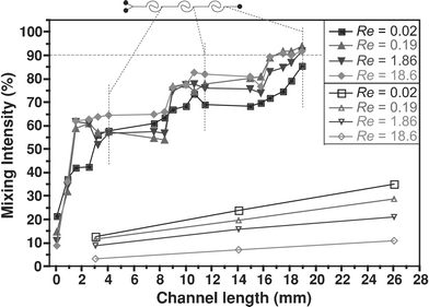 | ||
| Fig. 4 Mixing intensity within a two-arc, three-section spiral channel as a function of Re (filled symbols). The mixing intensity for a straight channel of equal length is also shown for comparison (open symbols). | ||
By increasing the length of individual spiral contours, higher levels of mixing can be achieved within the first spiral section (Fig. 5A). The increased length not only provides a longer time for diffusion at slow flow rates, but also helps in sustaining the transverse secondary flow. The strength of the transverse secondary flows is at a maximum in the arcs with the smallest radius of curvature (i.e., in the central region of the spiral), and hence at higher flow rates most mixing is expected to occur in these segments. Fig. 5B–E gives a measure of the mixing intensity along the contour of the first section of the channels (for a four-arc, six-arc, eight-arc and ten-arc designs) and its observed that most mixing occurs at the innermost region of the spiral flow path. Fig. 6 shows the mixing intensity at the end of each section for the four-arc, six-arc, eight-arc and ten-arc spiral channels. In the four-arc channel, mixing levels of 90% are achieved at the end of the second section, whereas in the eight- and ten-arc channels 90% mixing is obtained at the end of the first section.
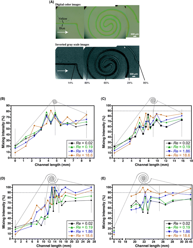 | ||
| Fig. 5 (A) Digital color images of the parallel blue and yellow streams entering the first section of an eight-arc spiral and corresponding gray-scale images depicting the evolution of the green mixed interface. Mixing intensity values as a function of Re along the contour of the section is indicated on the image. (B–E) Mixing intensity along the flow path of the first section of four-arc (B), six-arc (C), eight-arc (D) and ten-arc (E) spiral channels. | ||
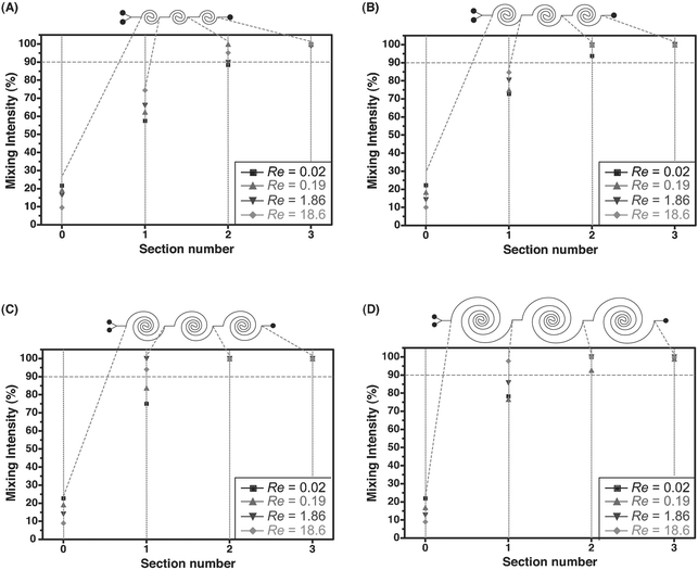 | ||
| Fig. 6 Mixing intensity as a function of Re at the end of each section for the four-arc (A), six-arc (B), eight-arc (C) and ten-arc (D) spiral channels. | ||
Mixing in spiral channels with a sudden expansion
Incorporating expansion vortex effects can further enhance the versatility of Dean mixing. This is evident in a two-arc channel, in which the central ‘S’-section is replaced by a straight segment that is 400 µm wide. The rest of the channel is maintained at a width of 80 µm. At higher flow rates, when the fluid encounters this sudden expansion in cross-sectional area, it separates from the wall resulting in a jet-like motion. At the same time, a pair of vortices develop at the entrance of this expansion on either side of this jet stream. These vortices become asymmetric with increasing Re.52,53 The combined effects of the expansion vortices with transverse Dean vortices result in a rapid increase of the mixed interface between two parallel streams (Fig. 7). At lower flow rates, these effects are not significant enough to substantially increase mixing levels. | ||
| Fig. 7 Gray-scale images depicting expansion of the mixed interface with increasing Re in a two-arc spiral channel incorporating expansion vortex effects. | ||
Conclusions
In this paper, we have presented a study of fluid mixing in spiral microchannels. We tested five different spiral designs incorporating variable lengths of spiral contours, and flow studies were carried out for a wide range of flow rates (Re = 0.02–18.6). At lower flow rates, diffusion is the primary mechanism by which mixing occurs. At higher flow rates, secondary Dean effects come into play and contribute to increased levels of mixing. As fluid travels downstream inside the spiral contours, it experiences an increase in the magnitude of centrifugal forces accompanied by a corresponding enhancement in mixing performance. The lengths of the spiral contours can be increased within individual spiral sections to achieve additional mixing in one section. Alternatively, multiple sections of spirals with fewer arcs can be designed to achieve mixing at higher flow rates since centrifugal effects are strongest at the innermost regions of the spiral. In either case, considerable flexibility is available to design channels on the basis of flow rates and available device footprint area. Moreover, by abruptly increasing the cross-sectional area of the spiral, expansion vortices result and can be harnessed to further reduce overall mixing lengths. The 3 mm-long straight section connecting successive spiral segments can also be shortened or eliminated. All channel designs in this work were fabricated in a single lithography step without the need for complex three-dimensional structures and cumbersome multi-layer alignment. No specialized laboratory equipment was used and the channels were fabricated in less than 30 min. The micromixer designs employed here can be readily integrated into most microfluidic systems that require simple planar geometries and efficient fluid mixing.Acknowledgements
This work was supported by the National Institutes of Health under grant NIH K22-HG02297.References
- D. J. Beebe, G. A. Mensing and G. M. Walker, Annu. Rev. Biomed. Eng., 2002, 4, 261 Search PubMed.
- M. A. Burns, B. N. Johnson, S. N. Brahmasandra, K. Handique, J. R. Webster, M. Krishnan, T. S. Sammarco, P. M. Man, D. Jones, D. Heldsinger, C. H. Mastrangelo and D. T. Burke, Science, 1998, 282, 484 CrossRef CAS.
- D. L. Chen, C. J. Gerdts and R. F. Ismagilov, J. Am. Chem. Soc., 2005, 127, 9672 CrossRef CAS.
- V. Hessel, S. Hardt and H. Löwe, Chemical Micro Process Engineering—Fundamentals, Modelling and Reactions, Wiley-VCH, Weinheim, 2004 Search PubMed.
- M. Krishnan, N. Agrawal, M. A. Burns and V. M. Ugaz, Anal. Chem., 2004, 76, 6254 CrossRef CAS.
- M. Krishnan, V. M. Ugaz and M. A. Burns, Science, 2002, 298, 793 CrossRef.
- K. D. Spitzack and V. M. Ugaz, Polymerase Chain Reaction in Miniaturized Systems: Big Progress in Little Devices, Microfluidic Techniques, Humana Press, Inc., Totowa, 2005, ch. 10, p. 321 Search PubMed.
- E. M. Lucchetta, J. H. Lee, L. A. Fu, N. H. Patel and R. F. Ismagilov, Nature, 2005, 434, 1134 CrossRef CAS.
- G. H. Seong and R. M. Crooks, J. Am. Chem. Soc., 2002, 124, 13360 CrossRef CAS.
- G. H. Seong, J. Heo and R. M. Crooks, J. Am. Chem. Soc., 2003, 75, 3161 CAS.
- T. Thorsen, S. J. Maerkl and S. R. Quake, Science, 2002, 298, 580 CrossRef CAS.
- W. N. Vreeland and L. E. Locascio, Anal. Chem., 2003, 75, 6906 CrossRef CAS.
- J. El-Ali, S. Gaudet, A. Günther, P. K. Sorger and K. F. Jensen, Anal. Chem., 2005, 77, 3629 CrossRef CAS.
- K. Jensen, Nature, 1998, 393, 735 CrossRef CAS.
- S. Hardt, K. S. Drese, V. Hessel and F. Schönfeld, Microfluid. Nanofluid., 2005, 1, 108 Search PubMed.
- V. Hessel, H. Löwe, A. Müller and G. Kolb, Chemical Micro Process Engineering—Processing and Plants, Wiley-VCH, Weinheim, 2005 Search PubMed.
- N.-T. Nguyen and Z. Wu, J. Micromech. Microeng., 2005, 15, R1 CrossRef.
- M. H. Oddy, J. G. Santiago and J. C. Mikkelsen, Anal. Chem., 2001, 73, 5822 CrossRef CAS.
- L.-H. Lu, K. S. Ryu and C. Liu, J. Microelectromech. Syst., 2002, 11, 462 CrossRef CAS.
- R. H. Liu, J. Yang, M. Z. Pindera, M. Athavale and P. Grodzinski, Lab Chip, 2002, 2, 151 RSC.
- Z. Yang, H. Goto, M. Matsumoto and R. Maeda, Electrophoresis, 2000, 21, 116 CrossRef CAS.
- F. G. Bessoth, A. J. deMello and A. Manz, Anal. Commun., 1999, 36, 213 RSC.
- N. Schwesinger, T. Frank and H. Wurmus, J. Micromech. Microeng., 1996, 6, 99 CrossRef CAS.
- J. Branebjerg, P. Gravesen, J. P. Krog and C. R. Nielsen, Fast Mixing by Lamination, Proceedings of IEEE MEMS Workshop, San Diego, CA, 1996, p. 441 Search PubMed.
- F. Schönfeld, V. Hessel and C. Hoffman, Lab Chip, 2004, 4, 65 RSC.
- T. J. Johnson, D. Ross and L. Locascio, Anal. Chem., 2002, 74, 45 CrossRef CAS.
- A. D. Stroock, S. K. W. Dertinger, A. Ajdari, I. Mezić, H. A. Stone and G. M. Whitesides, Science, 2002, 295, 647 CrossRef CAS.
- P. B. Howell, Jr., D. R. Mott, S. Fertig, C. R. Kaplan, J. P. Golden, E. S. Oran and F. S. Ligler, Lab Chip, 2005, 5, 524 RSC.
- R. H. Liu, M. A. Stremler, K. V. Sharp, M. G. Olsen, J. G. Santiago, R. J. Adrian, H. Aref and D. J. Beebe, J. Microelectromech. Syst., 2000, 9, 190 CrossRef.
- D. J. Kim, H. J. Oh, T. H. Park, J. B. Choo and S. H. Lee, Analyst, 2005, 130, 293 RSC.
- D. S. Kim, S. H. Lee, T. H. Kwon and C. H. Ahn, Lab Chip, 2005, 5, 739 RSC.
- S.-J. Park, J. K. Kim, J. Park, S. Chung, C. Chung and J. K. Chang, J. Micromech. Microeng., 2004, 14, 6 CrossRef.
- Y.-C. Chung, Y.-L. Hsu, C.-P. Jen, M.-C. Lu and Y.-C. Lin, Lab Chip, 2004, 4, 70 RSC.
- C.-C. Hong, J.-W. Choi and C. H. Ahn, Lab Chip, 2004, 4, 109 RSC.
- J. Melin, G. Giménez, N. Roxhed, W. van der Wijngaart and G. Stemme, Lab Chip, 2004, 4, 214 RSC.
- H. Song, J. D. Tice and R. F. Ismagilov, Angew. Chem., Int. Ed., 2003, 42, 768 CrossRef CAS.
- A. Günther, M. Jhunjhunwala, M. Thalmann, M. A. Schmidt and K. F. Jensen, Langmuir, 2005, 21, 1547 CrossRef.
- A. Bertsch, S. Heimgartner, P. Cousseau and P. Renaud, Lab Chip, 2001, 1, 56 RSC.
- D. Therriault, S. R. White and J. A. Lewis, Nat. Mater., 2003, 2, 265 CrossRef CAS.
- D. S. Kim, I. H. Lee, T. H. Kwon and D.-W. Cho, J. Micromech. Microeng., 2004, 14, 1294 CrossRef.
- S. A. Berger and L. Talbot, Annu. Rev. Fluid Mech., 1983, 15, 461 Search PubMed.
- F. Jiang, K. S. Drese, S. Hardt, M. Küpper and F. Schönfeld, AIChE J., 2004, 50, 2297 CrossRef CAS.
- F. Schönfeld and S. Hardt, AIChE J., 2004, 50, 771 CrossRef.
- Y. Yamaguchi, F. Takagi, T. Watari, K. Yamashita, H. Nakamura, H. Shimizu and H. Maeda, Chem. Eng. J., 2004, 101, 367 CrossRef CAS.
- Y. Yamaguchi, F. Takagi, K. Yamashita, H. Nakamura, H. Maeda, K. Sotowa, K. Kusakabe, Y. Yamasaki and S. Morooka, AIChE J., 2004, 50, 1530 CrossRef CAS.
- A. Y. Gelfgat, A. L. Yarin and P. Z. Bar-Yoseph, Phys. Fluids, 2003, 15, 330 Search PubMed.
- P. B. Howell, Jr., D. R. Mott, J. P. Golden and F. S. Ligler, Lab Chip, 2004, 4, 663 RSC.
- S. P. Vanka, C. M. Winkler, J. Coffman, E. Linderman, S. Mahjub and B. Young, Novel Low Reynolds Number Mixers for Microfluidic Application, Proceedings of ASME FEDSM ′03, Honolulu, HI, USA, July 6–10, 2003, p. 887 Search PubMed.
- S. P. Vanka, G. Luo and C. M. Winkler, AIChE J., 2004, 50, 2359 CrossRef CAS.
- A. P. Sudarsan and V. M. Ugaz, Anal. Chem., 2004, 76, 3229 CrossRef CAS.
- A. P. Sudarsan, J. Wang and V. M. Ugaz, Anal. Chem., 2005, 77, 5167 CrossRef CAS.
- N. Alleborn, K. Nandakumar, H. Raszillier and F. Durst, J. Fluid Mech., 1997, 330, 169 CrossRef CAS.
- W. Cherdon, F. Durst and J. H. Whitelaw, J. Fluid Mech., 1978, 84, 13.
| This journal is © The Royal Society of Chemistry 2006 |
