DOI:
10.1039/B511778J
(Paper)
Green Chem., 2006,
8, 70-77
Distribution of sulfur-containing aromatics between [hmim][Tf2N] and supercritical CO2: a case study for deep desulfurization of oil refinery streams by extraction with ionic liquids
Received
18th August 2005
, Accepted 19th October 2005
First published on 9th November 2005
Abstract
Stringent regulations of the maximum content of sulfur in transportation fuels have prompted an intense search for new processes of deep desulfurization to complement common catalytic hydrodesulfurization. One of the alternative processes under development involves extraction of sulfur-containing aromatic compounds (SAs) from diesel fuel and gasoline with ionic liquids (ILs). In these applications, recycling of ILs will be highly important, and reextraction of SAs from ILs with supercritical carbon dioxide (scCO2) appears to be a possible method to regenerate ILs. The design and feasibility assessment of supercritical reextraction requires the partition coefficients of SAs between ILs and scCO2. We used open tubular capillary-column chromatography to measure the partition coefficients of several SAs between 1-hexyl-3-methylimidazolium bis(trifluoromethylsulfonyl)imide ([hmim][Tf2N]) and scCO2, with [hmim][Tf2N] serving as the stationary liquid and scCO2 as the mobile phase (carrier fluid). The results confirm that the partition coefficients of SAs can be tuned within wide limits (over a decadic order of magnitude) by relatively modest changes in temperature (40–80 °C) and pressure (8.7–17.6 MPa). However, even the most favourable values of the partition coefficients of SAs between [hmim][Tf2N] and scCO2 suggest that feasibility of a large-scale supercritical reextraction process is questionable at best.
Introduction
In order to decrease SOx emissions, a number of countries have recently adopted stringent regulations of the maximum content of sulfur in transportation fuels. In the USA, the Environmental Protection Agency promulgated regulations stating that, effective September 1, 2006, the upper limit of sulfur content in the diesel fuel for use in highway vehicles will be 15 ppm (1 ppm = 1 mg kg−1).1 The European Commission proposed to reduce the sulfur content in the diesel fuel for use in highway vehicles to 10 ppm in every member state by January 2009.2 Currently, the prevailing technology for removing organic sulfur compounds from oil refinery streams is hydrodesulfurization (HDS), i.e., catalytic hydrogenation conducted at around 350 °C and at hydrogen pressure 3–10 MPa.3 The purpose of HDS is to convert the sulfur compounds to hydrogen sulfide and hydrocarbons. While the process is efficient with aliphatic sulfur structures, some sulfur-containing aromatic compounds (SAs), notably 4,6-dimethyldibenzothiophene (4,6-DMDBT) and other multiple alkylated derivatives of dibenzothiophene (DBT), are highly resistant to hydrotreatment and difficult to remove by HDS. Therefore, although efforts to improve the efficiency of HDS are under way,4 it is not clear whether HDS alone can secure conformity of the resultant fuels to the proposed limits of sulfur content. Consequently, the search has recently intensified for alternative, efficient, less-energy-demanding processes of deep desulfurization of oil-derived fuels.5,6
The search for alternative methods of deep desulfurization currently involves diverse techniques including reactive distillation,7 oxidative desulfurization in liquid–liquid systems,8–10 complexation in liquid–liquid systems11 or on an adsorbent,12,13 biodesulfurization by action of bacteria,14,15 and extraction with ionic liquids (ILs).16–20 The latter method makes use of the solubility differential between polarizable aromatic compounds and nonpolar aliphatic hydrocarbons in most imidazolium-containing ILs, and a variety of ILs have been tested for the purpose. Although the ILs containing the chloroaluminate anion were shown to be very effective in removing SAs,16,18 their sensitivity to moisture makes large-scale application difficult. Currently, therefore, attention is focused on hydrolysis-resistant ILs.19
In the process extraction of a refinery stream with ILs, regeneration and recycling of the SA-loaded IL will be essential, and several suggestions for separation of SAs from ILs have appeared in the literature. Zhang and Zhang17 suggested two ways to separate SAs (and the co-extracted hydrocarbons) depending on the properties of the IL employed. A hydrophilic, moisture-insensitive IL can be dissolved in water, with SAs separating or precipitating. As most ILs have no effective vapour pressure, water can be removed by evaporation under a stream of nitrogen at 110 °C. This procedure requires a large amount of heat, and would be difficult to integrate in a continuous process on a multi-ton scale. From a hydrophobic or moisture-sensitive IL, SAs can be removed by distillation. The distillation again requires heat, and it is only feasible with low-boiling SAs (e.g., thiophene) that are not likely to occur in hydrotreated diesel fuel. With high-boiling SAs such as DBT or 4,6-DMDBT, distillation is not effective. Esser et al.19 showed that DBT could not be removed from 1-butyl-3-methylimidazolium octylsulfate even after a 3-day stripping with air at 120 °C, and they suggested reextraction with low-boiling hydrocarbons such as pentane or hexane as a promising method to separate SAs from ILs. They also mentioned the possibility of using reextraction with supercritical CO2 (scCO2) but expressed doubts about the applicability of the process on a multi-ton scale because of energy expenses.
Supercritical fluid extraction of organic nonelectrolytes from ILs with scCO2 was originally suggested by Blanchard et al.21,22 Although the solvating power of scCO2 is generally lower as compared with organic solvents, extraction with scCO2 has a specific feature with potential importance to separation of SAs from ILs. On decompression of the fluid solution in scCO2, the solvating power of the expanding CO2 decreases rapidly, and the dissolved SAs and co-extracted hydrocarbons nucleate and can be separated from CO2. The Joule–Thomson cooling of the expanding mixture assists the solidification of the precipitating material. Consequently, SAs and co-extracted hydrocarbons can be expected to come out of the process in a concentrated form rather than being diluted in a liquid solvent. In our judgement, this particular feature makes the reextraction of SAs from ILs with scCO2 worthy of closer inspection. It is possible to consider a continuous, bicyclic extraction process shown schematically in Fig. 1. In the first (left) counter-current extraction column operated at ambient temperature and pressure, the fuel stream is contacted with IL to extract SAs as discussed by others before.16–20 In the second counter-current extraction column operated at a temperature and pressure above the respective critical data of pure CO2 (tc = 30.98 °C, Pc = 7.377 MPa), scCO2 is used to reextract the dissolved compounds from IL. On expansion of the fluid solution, the dissolved compounds nucleate, aggregate and can be removed for further processing/disposal while CO2 is recompressed and recycled. On decompression of the regenerated IL, CO2 dissolved in the IL during the high-pressure reextraction is released and returned to the CO2 cycle, and the IL returns to the first extraction column.
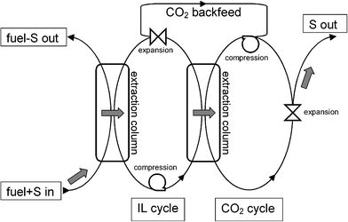 |
| | Fig. 1 Continuous bicyclic process of fuel desulfurization with IL and scCO2. Grey arrows mark the desirable route of sulfur-containing aromatic compounds. | |
The most important data needed for feasibility assessment of the reextraction step in Fig. 1 are the partition coefficients of SAs between IL and scCO2. The purpose of this study is to provide the partition coefficient data measured in a model system.
Determination of the partition coefficients
At present, the available data on partitioning of low-volatility solutes between both phases in IL–scCO2 systems come mostly from retention measurements by open tubular capillary-column supercritical fluid chromatography (SFC),23,24 with the recent exception of the IR-spectroscopic study by Sakellarios and Kazarian.25 SFC yields the limiting partition coefficients at an effective infinite dilution of the solute in both phases, and we also used SFC in the present study, with the IL employed as the stationary liquid and scCO2 as the mobile phase (carrier fluid).
Selection of IL and SAs for the case study
We used 1-hexyl-3-methylimidazolium bis(trifluoromethylsulfonyl)imide ([hmim][Tf2N]) as a model IL. From the perspective of deep desulfurization of oil refinery streams, this choice may seem surprising as the ILs containing Tf2N anion have not been investigated for the purpose,16–20 probably because they were not readily accessible from cheap starting materials. Our study, however, was focused on the distribution of SAs between IL and scCO2 rather than on the distribution of SAs between a fuel stream and IL. To evaluate the process feasibility of the reextraction step in Fig. 1, it is expedient to select an IL–scCO2 system in which the reextraction of SAs can be expected to be relatively easy, i.e., a system where the distribution of SAs will be shifted to the scCO2 phase to the maximum possible extent. A simple consideration based on the regular solution theory suggests that an IL with low cohesive energy density (c) should be selected. In a series of 1-butyl-3-methylimidazolium ILs, [bmim][BF4], [bmim][PF6], [bmim][Tf2N] and [bmim][TfO], c values are 998, 912, 650 and 620 J cm−3, respectively, at 25 °C.26 Because of the longer alkyl chain on the imidazolium ring, c of [hmim][Tf2N] can be expected to be even lower than c of [bmim][Tf2N]. This was recently confirmed experimentally.27 Besides, [hmim][Tf2N] has been included in a recent study28 of high-pressure phase equilibria in IL–CO2 systems, and shown to be one of the best solvents for scCO2 among the ILs studied. This finding also reflects the low c value of [hmim][Tf2N]. As [hmim][Tf2N] has a relatively low viscosity,29–31 it is also useful for the secondary purpose of the present work, namely, for a feasibility test of SFC measurements in an open tubular column with a low-viscosity IL.
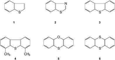
Fig. 2 shows the structures of the SAs included in this study, namely, benzo[b]thiophene = thianaphthene (1), benzothiazole (2), DBT (3), 4,6-DMDBT (4), phenoxathiin (5) and thianthrene (6).
Results and discussion
The quantities pertaining to the solute, IL and scCO2 will be denoted by subscripts 1, 2 and 3, respectively. In column chromatography, the retention factor of the solute, k1, is given bywhere t0 is the column hold-up time and tR is the retention time of the solute. The retention factor reflects the distribution of a trace amount of the solute (= SA compound) between the gas and the liquid phases in the column. To consider the efficiency of reextraction of the SA compound from [hmim][Tf2N] with scCO2, it is expedient to define a “practical” partition coefficient of SA by| | | KN = (m1G/m1L)(m2L/m3G) | (2) |
where m1G and m1L are the equilibrium masses of the solute in the gas and the liquid phases, respectively, m2L is the mass of IL in the liquid phase, and m3G is the mass of CO2 in the gas phase. Under conditions of linear chromatography (= independence of both k1 and KN on the solute concentration in either phase), KN is related to k1 by
Being defined on a CO2-free-IL basis, the values of KN are not thermodynamically rigorous partitioning characteristics because alkylimidazolium ILs typically absorb large amounts of scCO2.21,28,32–35 However, the KN data are useful for evaluation of attainable extraction factors and for feasibility assessment of the counter-current reextraction of SAs from [hmim][Tf2N] with scCO2. The pertinent value of m2L to be used in eqn (3) can be obtained from the initial amount of [hmim][Tf2N] in the column and from the time dependence of k1 for a reference solute (see below). The value of m3G can be calculated from the temperature, pressure and void volume of the column using the equation of state for CO2 developed by Span and Wagner.36
Partition coefficients of SAs
In contrast with our previous SFC studies on [bmim][PF6]23 and [bmim][BF4],24 we observed a gradual decrease of the amount of [hmim][Tf2N] in the column during the retention measurements, with the rate of decrease depending on the column preparation method (see Experimental section). The probable reason for the decrease was a higher solubility of [hmim][Tf2N] in scCO2 as compared with both [bmim][PF6] and [bmim][BF4]. This view is supported by the cohesive energy density considerations mentioned above. On the basis of the regular solution theory and the literature values of c,26,27 therefore, an estimated order of IL solubility in scCO2 at a particular temperature and pressure would be [bmim][BF4] < [bmim][PF6] << [bmim][Tf2N] < [hmim][Tf2N].
At higher densities of scCO2, we even observed a mechanical washout of a small amount of CO2-expanded [hmim][Tf2N] from the column. This was indicated by spikes in the flame ionization detector response suggesting that microdroplets of IL were washed out from the column to the detector by the flow of scCO2. Such an explanation has been supported by the relatively low viscosity of Tf2N-containing ILs.29–31 Moreover, the viscosity of CO2-saturated [hmim][Tf2N] is likely to be significantly lower than the viscosity of pure [hmim][Tf2N] at the same temperature. This can be expected because of several previous studies37–39 reporting a marked reduction of viscosity of [bmim][PF6] on CO2 dissolution at elevated pressures.
To correct for the gradual decrease in the amount of [hmim][Tf2N] in the column, the retention factors were recalculated to the initial amount of IL in the column using the ratio between the current value and the initial value of the retention factor, knaph, of naphthalene at 60 °C and 12 MPa. The initial value of knaph was measured immediately after the preparation of the column. The current value of knaph relevant to the retention factors of SAs at a particular temperature and pressure was interpolated between the knaph values measured immediately before and after the measurement of the retention factors of SAs at the particular temperature and pressure.
The retention factors corrected as described above displayed the usual appearance of the logarithmic plots of k1versus density of CO2. A sample plot at 60 °C is shown in Fig. 3. It is interesting to note the reversal in elution order between DBT and 4,6-DMDBT with increasing density of CO2. The reversal was observed at 40 °C and 80 °C as well. The corrected values of k1 were used to calculate the partition coefficients KN from eqn (3), and the results are listed in Table 1. Within the region of temperature and pressure covered by the measurements, solute partition coefficients vary widely, with the ratio between the maximum and the minimum value in any individual solute being 10 or more. The primary factor determining the accuracy of the data in Table 1 is the uncertainty in the initial amount of [hmim][Tf2N] in the column. The accuracy of the KN values in Table 1 can be estimated to be ±13% of the mean value. The relative values for the individual solutes at a particular temperature and pressure are more robust, and their accuracy can be estimated to be within 4% of the mean value.
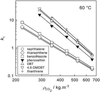 |
| | Fig. 3 Retention factors vs. CO2 density at 60 °C. | |
Table 1 Mean values of partition coefficients
|
t/°C |
P/MPa |
ρ
CO2/kg m−3 |
100 ×
KN |
| Naphthalene |
Thianaphthene |
Benzothiazole |
Phenoxathiin |
DBT |
4,6-DMDBT |
Thianthrene |
| 40 |
8.8 |
429 |
1.99 |
1.94 |
1.74 |
0.419 |
|
|
|
| 40 |
9.2 |
532 |
3.91 |
3.60 |
3.26 |
0.947 |
0.624 |
0.590 |
0.763 |
| 40 |
10.5 |
660 |
6.89 |
6.54 |
5.92 |
2.15 |
1.44 |
1.43 |
1.46 |
| 40 |
13.2 |
747 |
8.99 |
8.59 |
8.40 |
4.02 |
2.63 |
2.80 |
2.50 |
| |
|
|
|
|
|
|
|
|
|
| 60 |
8.7 |
221 |
0.876 |
0.808 |
0.556 |
|
|
|
|
| 60 |
10 |
290 |
1.57 |
1.44 |
1.07 |
0.226 |
0.153 |
0.136 |
|
| 60 |
10.9 |
350 |
2.54 |
2.31 |
1.85 |
0.478 |
0.323 |
0.304 |
0.236 |
| 60 |
12.1 |
442 |
3.85 |
3.54 |
2.94 |
0.913 |
0.618 |
0.607 |
0.484 |
| 60 |
13.3 |
524 |
5.90 |
5.48 |
4.70 |
1.75 |
1.19 |
1.23 |
0.984 |
| 60 |
16.7 |
657 |
9.13 |
8.73 |
8.06 |
4.02 |
2.77 |
3.02 |
2.60 |
| |
|
|
|
|
|
|
|
|
|
| 80 |
10 |
222 |
1.63 |
1.49 |
1.03 |
0.187 |
|
|
|
| 80 |
11.8 |
289 |
2.45 |
2.25 |
1.65 |
0.380 |
|
|
|
| 80 |
13.3 |
352 |
3.59 |
3.33 |
2.55 |
0.726 |
0.512 |
0.471 |
0.376 |
| 80 |
15.3 |
440 |
5.78 |
5.31 |
4.35 |
1.57 |
1.10 |
1.09 |
0.891 |
| 80 |
17.6 |
526 |
7.90 |
|
|
2.79 |
1.93 |
2.03 |
1.68 |
Implications for counter-current reextraction of SAs from IL with scCO2
If a SA compound is extracted from IL with scCO2 in a counter-current extraction process with n stages, the relative decrease in the concentration of SA in the IL can be obtained from40| | | w1R/w1F = (E
− 1)/(En+1
− 1) | (4) |
where w1F is the mass fraction of SA in the feed IL and w1R is the mass fraction of SA in the raffinate IL (on a CO2-free-IL basis). It follows from eqn (4) that, for counter-current extraction to be feasible, the extraction factor E has to be greater than 1. The extraction factor is given bywhere F3G is the mass flow rate of scCO2 in the gaseous phase and F2L is the mass flow rate of IL in the liquid phase. It should be noted that the value of F3G does not include the portion of CO2 that will dissolve in the IL at the operating temperature and pressure of extraction.
The data listed in Table 1 indicate that, for a particular SA at a particular pressure of scCO2, KN increases with decreasing temperature. Therefore, in order to base further considerations on the maximum attainable partition coefficients of SAs between [hmim][Tf2N] and scCO2 while keeping pressure within reasonable limits, we extrapolated the data in Table 1 to 35 °C. We did not attempt an extrapolation to a lower temperature because of proximity to the critical temperature of CO2. In large-scale applications, the enhanced compressibility in the near-critical region makes near-critical CO2 difficult to work with. In an analogy with variations of k1 with temperature (T, in kelvins) and density of CO2 (ρCO2) known from SFC,41–43 the extrapolations were accomplished assuming validity of the linear relationships
| | | lnKN = alnρCO2 + b [T = const.] | (6) |
and
| | | lnKN = d/T + e [ρCO2 = const.] | (7) |
The coefficients a and b in eqn (6) were obtained by regression of the data in Table 1 at the three temperatures, and used to obtain interpolated values of KN at a set of fixed densities of CO2. At the individual densities, the interpolated data were used to fit d and e in eqn (7) and to estimate KN at 35 °C and at the respective density of CO2. Fig. 4 shows the resultant partition coefficients at 35 °C, with the pressure values obtained from T and ρCO2 using the equation of state.36
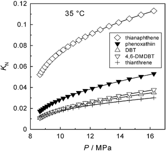 |
| | Fig. 4 Partition coefficients KN at 35 °C (extrapolated data). | |
From the KN values at 35 °C (Fig. 4), the minimum values of F3G/F2L needed to make E > 1 in the individual SAs are readily obtained using eqn (5), and the results are plotted in Fig. 5. Even at the highest pressure shown in Fig. 5, the relative flow rates F3G/F2L needed to make E > 1 appear too high for a feasible reextraction, with the possible exception of thianaphthene. Moreover, the quantities F3G and F2L are mass flow rates. As the density of CO2-saturated [hmim][Tf2N]28 is invariably higher than that of scCO2 at the respective temperature and pressure, the corresponding ratio of volumetric flow rates will be even more prohibitive to a feasible reextraction.
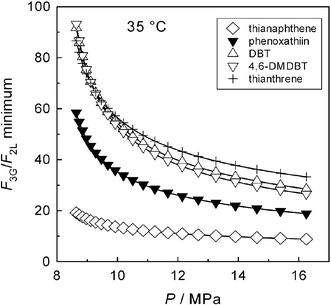 |
| | Fig. 5 Minimum values of the scCO2/IL relative mass flow rate needed to make supercritical reextraction of SAs feasible (E > 1). | |
Thermal effects associated with reextraction with scCO2
Because of the very large flow rate of scCO2 needed to make the reextraction possible, a brief consideration is given here to the thermal effects associated with keeping a steady state (thermal balance) in the CO2 cycle shown in Fig. 1. The expansion and compression of CO2 in the reextraction cycle are accompanied by changes in the temperature of the gas. As the thermodynamic path of expansion is not known and depends on the particular process arrangement, the isenthalpic and isentropic paths are considered here as models. The quantity governing the temperature change on isenthalpic expansion of a fluid is the derivative (∂T/∂P)H called the Joule–Thomson coefficient or the isenthalpic throttling coefficient. For CO2, the Joule–Thomson coefficient at a particular temperature and density can be calculated from the equation of state for CO2.36 The quantity governing the temperature change on isentropic expansion of a fluid is (∂T/∂P)S, the isentropic temperature–pressure coefficient. The two coefficients are related through the thermodynamic identity| | | (∂T/∂P)S = (∂T/∂P)H + 1/(ρCP) | (8) |
where ρ is the density and CP is the isobaric heat capacity of the fluid. In CO2, these properties can also be obtained from the Span–Wagner equation of state.36Fig. 6 shows the calculated values of (∂T/∂P)H and (∂T/∂P)S of CO2 within the relevant region of temperature and pressure. As both coefficients are positive and relatively large, especially at lower pressures, they indicate a significant cooling of CO2 on expansion along either isentropic or isenthalpic paths. The decrease in temperature alone would be beneficial for solidification of the material nucleating from the expanding fluid. However, Fig. 5 shows that very large CO2/IL relative flow rates will be needed in the reextraction step. At the temperature and pressure conditions shown in Fig. 6, CP values of CO2 range within 0.9–5.7 kJ kg−1 K−1. Consequently, to keep the reextraction process in thermal balance (steady state), large amounts of heat will have to be transferred between the expanding and the compressed CO2, and the heat transfer effects can be difficult to accommodate within the multi-ton scale process typical of oil refinery operations.
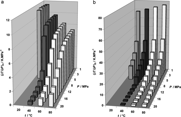 |
| | Fig. 6 Joule–Thomson coefficient (a) and isentropic temperature–pressure coefficient (b) of CO2 as functions of temperature and pressure. | |
Conclusion
SFC retention measurements were employed here to obtain the partition coefficients of several SAs between [hmim][Tf2N] and scCO2, and the KN values were used to derive other properties relevant to counter-current reextraction of the SAs from [hmim][Tf2N] with scCO2. The results indicate that, for the reextraction of SAs from IL with scCO2 to be feasible, competitive in a large-scale process and efficient even with heavier SAs not included in this study (e.g., benzonaphthothiophenes), an IL would have to be found with significantly (∼10 times) higher values of KN as compared with the present data for [hmim][Tf2N]. Simple considerations based on the regular solution theory suggest that the IL would have to display a very low value of cohesive energy density. Therefore, if found, the IL would most likely be soluble in scCO2 (and in the fuel stream) to the extent precluding it from being used for deep desulfurization of oil refinery streams. Thermal effects associated with expansion and compression of CO2 can present another hindrance to a large-scale reextraction of SAs from ILs with scCO2.
Experimental
Materials
Benzo[b]thiophene (thianaphthene) (99%), benzothiazole (96%), DBT (>99%), 4,6-DMDBT (97%), thianthrene (97%), phenoxathiin (97%), naphthalene (>99%), ammonium hydrogen difluoride (>95%), hexane (>99.9%), methanol (>99.9%) and methylene chloride (99.9%) were purchased from Sigma-Aldrich s. r. o. (Prague, Czech Republic) and used as received. Ionic liquid [hmim][Tf2N] was obtained from Merck s. r. o. (Prague, Czech Republic). To remove moisture from [hmim][Tf2N] prior to the column preparation, 1 cm3 of [hmim][Tf2N] was purged with a gentle stream of nitrogen in a gas chromatographic oven at a programmed temperature, with the final period of 12 hours at 120 °C. Carbon dioxide (purity grade 4.5, mole fraction of residual water <5 × 10⁻⁶) was obtained from Messer Griesheim GmbH (Krefeld, Germany). Fused-silica capillary tubing for preparation of the column and of the outlet restrictor was purchased from CACO s. r. o. (Bratislava, Slovak Republic).
Apparatus
A schematic diagram of the experimental arrangement is shown in Fig. 7. Chromatographic retention measurements were carried out using a modified Varian 3700 gas chromatograph employed before.23,24 High-pressure CO2 was delivered by a HPP 5001 syringe pump (Laboratorní přístroje, Prague, Czech Republic) equipped with an in-house-developed pressure control system. Injections were performed with a helium-actuated high-pressure injection valve (model ACI4W, Valco Instrument Co., Schenkon, Switzerland) fitted with a 60 nL sampling rotor. The detector response data were collected and processed with a CSW32 chromatography station (DataApex s. r. o., Prague, Czech Republic).
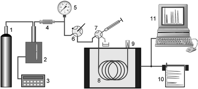 |
| | Fig. 7 Overall layout of the chromatographic apparatus. 1 CO2 supply tank, 2 HPLC pump modified for isobaric operation, 3 pressure controller, 4 stainless-steel filters, 5 pressure gauge, 6 main control valve, 7 injection valve, 8 open tubular capillary column, 9 flow restrictor + detector, 10 line recorder, 11 data acquisition system. | |
Column preparation
Compared with our previous SFC experiments employing [bmim][PF6]23 and [bmim][BF4],24 it was considerably more difficult in the present study to prepare a [hmim][Tf2N] column with at least sufficient stability. The open tubular columns with [bmim][PF6] and [bmim][BF4] in our previous studies were sufficiently stable, and we did not observe a measurable loss of either [bmim][PF6] or [bmim][BF4] from the column during the set of chromatographic measurements. When applying to [hmim][Tf2N] the same column preparation method as that used for [bmim][PF6] and [bmim][BF4], we observed a rapid washout of [hmim][Tf2N] from the column by the flowing CO2. The probable causes of this behaviour are discussed in the Results and Discussion section.
To promote adhesion of [hmim][Tf2N] to the inner wall of the column, we etched the inner surface of the fused-silica capillary prior to applying the surface modification procedure employed before.23,24 It should be noted that etching of the capillary is a rather delicate operation. If etching is too intense, it can produce a brittle capillary that breaks easily, especially if exposed to a high-pressure fluid such as in the present application. Initially, we used etching with either aqueous hydrofluoric acid (40 wt%) or with vapour of aqueous hydrofluoric acid. However, both these methods failed to produce a uniformly etched surface. Satisfactory results were only obtained from etching the inner surface with saturated solution of ammonium hydrogen difluoride in methanol at 25 °C for 48 hours. This technique produced a uniformly etched surface, and the capillary retained excellent flexibility for easy coiling. After etching the inner wall of the capillary, we applied the surface modification procedure used in our previous studies, and only then was the pre-treated capillary coated with [hmim][Tf2N]. The coating procedure consisted of filling the capillary with a solution of [hmim][Tf2N] in methylene chloride, sealing one end of the capillary, and careful evaporation of methylene chloride by applying vacuum to the open end. The resultant column (2745 mm long × 95 µm i.d.) initially contained 4.4 × 10⁻⁷ mol [hmim][Tf2N], with an equivalent film thickness of IL equal to 0.18 µm (at 25 °C). The rate of decrease of the amount of [hmim][Tf2N] in the column was sufficiently low to provide credible values of retention factors. During the whole sequence of measurements needed to produce the data listed in Table 1, 23% of the initial amount of [hmim][Tf2N] was removed from the column by scCO2.
Measurement procedure
At a particular temperature and density, triplicate measurements of the solute retention factors were carried out. The injection solutions were prepared so as to secure sufficient resolution of the solute peaks. Hexane was used as the injection solvent and each solution contained naphthalene as a reference, with the concentrations of individual solutes ranging within 1.5–3 mg cm−3. The column hold-up time was marked by injecting a small amount of methane simultaneously with every injection of solutes as described before.23,24 The retention factors of SAs were measured along three isotherms (40, 60 and 80 °C) with the mean pressure in the column within 8.7–17.6 MPa. The pressure drop along the column was calculated from the Hagen–Poiseuille equation using the correlation for CO2 viscosity developed by Vesovic et al.,44 and it did not exceed 0.015 MPa. To minimize the uncertainty induced by the decreasing amount of [hmim][Tf2N] in the column, the data were measured in the sequence of increasing density of scCO2. At a particular stage of measurement, the current amount of [hmim][Tf2N] in the column was obtained from the current value of the retention factor of naphthalene as described in the Results and Discussion section.
Acknowledgements
We thank Prof. Dr.-Ing. Wolfgang Wagner (Institute of Thermo- and Fluid Dynamics, Faculty of Mechanical Engineering, University of Bochum, Germany) and Prof. Dr.-Ing. Roland Span (Chair of Thermodynamics and Energy Technology, Institute for Energy and Process Technology, University of Paderborn, Germany) for the software package based on the wide-range thermodynamic formulation for CO2 (ref. 36). We acknowledge the Grant Agency of the Academy of Sciences of the Czech Republic for financial support of this work through Project No. A4031301.
References
- Regulatory Announcement: Heavy-Duty Engine and Vehicle Standards and Highway Diesel Fuel Sulfur Control Requirements, United States Environmental Protection Agency, Air and Radiation, EPA420-F-00-057, Washington (DC), December 2000, available from http://www.epa.gov/otaq/regs/hd2007/frm/f00057.pdf..
- EU-Directives: 1998/70/EC, OJ L 350, 28.12.1998, p. 58 (Directive as amended by Commission Directive 2000/71/EC OJ L 287, 14.11.2000, p. 46), and 2003/17/EC OJ L 76, 22.3.2003, p. 10.
- M. J. Girgis and B. C. Gates, Ind. Eng. Chem. Res., 1991, 30, 2021–2058 CrossRef CAS.
- S. K. Bej, S. K. Maity and U. T. Turaga, Energy Fuels, 2004, 18, 1227–1237 CrossRef CAS.
- I. V. Babich and J. A. Moulijn, Fuel, 2003, 82, 607–631 CrossRef CAS.
- C. Song, Catal. Today, 2003, 86, 211–263 CrossRef CAS.
- T. Viveros-García, J. A. Ochoa-Tapia, R. Lobo-Oehmichen, J. A. de los Reyes-Heredia and E. S. Pérez-Cisneros, Chem. Eng. J., 2005, 106, 119–131 CrossRef CAS.
- K. Yazu, Y. Yamamoto, T. Furuya, K. Miki and K. Ukegawa, Energy Fuels, 2001, 15, 1535–1536 CrossRef CAS.
- J. M. Campos-Martin, M. C. Capel-Sanchez and J. L. G. Fierro, Green Chem., 2004, 6, 557–562 RSC.
- A. Deshpande, A. Bassi and A. Prakash, Energy Fuels, 2005, 19, 28–34 CrossRef CAS.
- S. G. McKinley and R. J. Angelici, Energy Fuels, 2003, 17, 1480–1486 CrossRef CAS.
- A. J. Hernández-Maldonado and R. T. Yang, Ind. Eng. Chem. Res., 2003, 42, 3103–3110 CrossRef CAS.
- M. Sévignon, M. Macaud, A. Favre-Réguillon, J. Schulz, M. Rocault, R. Faure, M. Vrinat and M. Lemaire, Green Chem., 2005, 7, 413–420 RSC.
- K. Kirimura, T. Furuya, Y. Nishii, Y. Ishii, K. Kino and S. Usami, J. Biosci. Bioeng., 2001, 91, 262–266 Search PubMed.
- A. B. Martin, A. Alcon, V. E. Santos and F. Garcia-Ochoa, Energy Fuels, 2005, 19, 775–782 CrossRef CAS.
- A. Bösmann, L. Datsevich, A. Jess, A. Lauter, C. Schmitz and P. Wasserscheid, Chem. Commun., 2001, 2494–2495 RSC.
- S. Zhang and Z. C. Zhang, Green Chem., 2002, 4, 376–379 RSC.
- S. Zhang, Q. Zhang and Z. C. Zhang, Ind. Eng. Chem. Res., 2004, 43, 614–622 CrossRef CAS.
- J. Esser, P. Wasserscheid and A. Jess, Green Chem., 2004, 6, 316–322 RSC.
- C. Huang, B. Chen, J. Zhang, Z. Liu and Y. Li, Energy Fuels, 2004, 18, 1862–1864 CrossRef CAS.
- L. A. Blanchard, D. Hancu, E. J. Beckman and J. F. Brennecke, Nature, 1999, 399, 28–29 CrossRef.
- L. A. Blanchard and J. F. Brennecke, Ind. Eng. Chem. Res., 2001, 40, 287–292 CrossRef CAS.
- J. Planeta and M. Roth, J. Phys. Chem. B, 2004, 108, 11244–11249 CrossRef CAS.
- J. Planeta and M. Roth, J. Phys. Chem. B, 2005, 109, 15165–15171 CrossRef CAS.
- N. I. Sakellarios and S. G. Kazarian, J. Chem. Thermodyn., 2005, 37, 621–626 CrossRef CAS.
- K. Swiderski, A. McLean, C. M. Gordon and D. H. Vaughan, Chem. Commun., 2004, 2178–2179 RSC.
- S. H. Lee and S. B. Lee, Chem. Commun., 2005, 3469–3471 RSC.
- S. N. V. K. Aki, B. R. Mellein, E. M. Saurer and J. F. Brennecke, J. Phys. Chem. B, 2004, 108, 20355–20365 CrossRef CAS.
- J. M. Crosthwaite, M. J. Muldoon, J. K. Dixon, J. L. Anderson and J. F. Brennecke, J. Chem. Thermodyn., 2005, 37, 559–568 CrossRef CAS.
- H. Tokuda, K. Hayamizu, K. Ishii, M. Abu Bin Hasan Susan and M. Watanabe, J. Phys. Chem. B, 2004, 108, 16593–16600 CrossRef CAS.
- H. Tokuda, K. Hayamizu, K. Ishii, M. Abu Bin Hasan Susan and M. Watanabe, J. Phys. Chem. B, 2005, 109, 6103–6110 CrossRef CAS.
- L. A. Blanchard, Z. Gu and J. F. Brennecke, J. Phys. Chem. B, 2001, 105, 2437–2444 CrossRef CAS.
- A. P.-S. Kamps, D. Tuma, J. Xia and G. Maurer, J. Chem. Eng. Data, 2003, 48, 746–749 CrossRef CAS.
- A. Shariati and C. J. Peters, J. Supercrit. Fluids, 2004, 29, 43–48 CrossRef CAS.
- A. Shariati, K. Gutkowski and C. J. Peters, AIChE J., 2005, 51, 1532–1540 CrossRef CAS.
- R. Span and W. Wagner, J. Phys. Chem. Ref. Data, 1996, 25, 1509–1596 CAS.
- S. N. Baker, G. A. Baker, M. A. Kane and F. V. Bright, J. Phys. Chem. B, 2001, 105, 9663–9668 CrossRef CAS.
- J. Lu, C. L. Liotta and C. A. Eckert, J. Phys. Chem. A, 2003, 107, 3995–4000 CrossRef CAS.
- Z. Liu, W. Wu, B. Han, Z. Dong, G. Zhao, J. Wang, T. Jiang and G. Yang, Chem.—Eur. J., 2003, 9, 3897–3903 CrossRef CAS.
-
http://www.cheresources.com/extraction.shtml, The Chemical Engineers' Resource Page, Midlothian (VA), USA, 2004.
- U. van Wasen, I. Swaid and G. M. Schneider, Angew. Chem., Int. Ed. Engl., 1980, 19, 575–587 CrossRef.
- H. H. Lauer, D. McManigill and R. D. Board, Anal. Chem., 1983, 55, 1370–1375 CrossRef CAS.
- J.-J. Shim and K. P. Johnston, J. Phys. Chem., 1991, 95, 353–360 CrossRef CAS.
- V. Vesovic, W. A. Wakeham, G. A. Olchowy, J. V. Sengers, J. T. R. Watson and J. Millat, J. Phys. Chem. Ref. Data, 1990, 19, 763–808.
|
| This journal is © The Royal Society of Chemistry 2006 |
Click here to see how this site uses Cookies. View our privacy policy here. 
