Cofacial porphyrin multilayers via layer-by-layer assembly†
Dong-Chan
Lee‡
,
Gustavo M.
Morales
,
Youngu
Lee
and
Luping
Yu
*
Department of Chemistry and James Franck Institute, The University of Chicago, Chicago, Illinois 60637, USA. E-mail: lupingyu@midway.uchicago.edu; Fax: (+1) 773 702 0805; Tel: (+1) 773 702 8698
First published on 14th November 2005
Abstract
This paper reports a new layer-by-layer assembly approach to fabricate multilayers of cofacially aligned porphyrins on solid supports by a selective siloxane formation utilizing tetraphenylporphyrinatosilicon(IV) chloride as the building block.
Surface modification on electrodes such as metal, indium-tin oxide (ITO) and silicon plays a crucial role in organic semiconductor devices.1 In this paper, we describe a new layer-by-layer surface immobilization approach based on selective siloxane formation to immobilize electroactive porphyrin moieties. We chose tetraphenylporphyrinatosilicon(IV) chloride (TPP-SiCl2)2 as the building block to demonstrate the feasibility of this approach. There are three reasons to select the TPP-SiCl2 as the building blocks: 1) many macrocyclic silane complexes have been reported and the TPP-SiCl2 is a representative example that can be synthesized relatively easily; 2) the two chlorides are connected in different faces in TPP that allow sequential reaction on the surface and to further anchor functional molecules; 3) porphyrins and phthalocyanines are being extensively investigated in artificial photosynthetic applications and electro-optic materials. For example, phthalocyaninato-polysiloxanes (Pc-PS) from dihydroxysiliconphthalocyanine monomers3 with phthalocyanines cofacially aligned along the polysiloxane backbone shows large electrical conductivity after chemical doping. Anisotropic conductivity in highly organized Langmuir–Blodgett films of pristine Pc-PS was also observed.4
Several approaches are available to build up multiporphyrin or phthalocyanine systems on solid supports with control at the nanometer or subnanometer scale, such as metal-mediated assembly,5 electrostatic interactions,6 covalent bonding,7 or Langmuir–Blodgett techniques.8 Despite these advances, it is rather difficult to produce robust macrocycles assemblies with effective cofacial overlap. The approach reported here is different from the existing ones both in its simplicity and versatility for further functionalization.
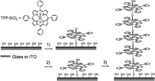
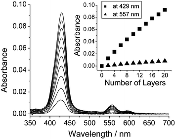
TPP-SiCl2 was synthesized according to previous reports.2 Immobilization can be carried out on either hydrophilic glass or ITO as illustrated in Scheme 1 under anhydrous conditions. The substrates were carefully cleaned and dried. They were dipped into a CH2Cl2 solution of TPP-SiCl2 for 30 min and rinsed extensively with dry CH2Cl2 to form a monolayer. Subsequently, the monolayer was immersed in deionized water for 5 min to transform the surface Si–Cl to Si–OH. After the resulting monolayer has been rinsed with deionized water and ethyl alcohol, dried thoroughly with a stream of N2, followed by drying over P2O5 under reduced pressure at room temperature, it can be used to immobilize more layers by repeating the process. Deposition of each layer was monitored by UV/Vis spectroscopy. As shown in Fig. 1, the Soret band of porphyrin at 429 nm and the Q-band at 557 nm increased fairly linearly as a function of the number of layers. This indicates that the assembly process is highly reproducible and excludes a possible physisorption. Nonetheless, a deviation from linearity in the optical density appears as the number of layers increases beyond 8. Surface roughness is the main reason for this deviation. On a rough surface, the oligomer chains are not completely perpendicular to surface. When the chains grow to a certain length, the inter-chain steric hindrance at the chain head will make surface reaction incomplete.
 | ||
| Scheme 1 Schematic representation of the procedure for the layer-by-layer porphyrin multilayer assembly: 1) TPP-SiCl2; 2) H2O; 3) repetition of the steps 1) and 2). | ||
 | ||
| Fig. 1 UV/Vis spectrum of multilayers of porphyrin. The inset represents the plot of increase of absorbance at Soret band (429 nm) and Q band (557 nm) versus the number of layers. | ||
Due to the non-planarity of the porphyrin ring in hexacoordinate silicon porphyrin complexes2a,d the π–π overlap is not very pronounced. In the related phthalocyaninato-oligo and polysiloxane, the Si–O–Si backbone maintains a 180° bond angle with an inter-planar ring distance of 3.33 Å which is smaller than the normal distance for stacked aromatic rings, as revealed by X-ray diffraction studies.3d This enforced ring placement with each phthalocyanine slightly buckled away from central ring causes spectral change due to effective π-orbital overlap. Unlike Pc-PSs, there is no spectral change in UV/Vis in this porphyrin multilayer assembly as the number of layer increases, indicating a weak π-orbital overlap.
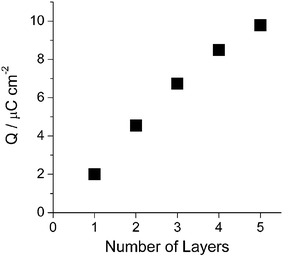
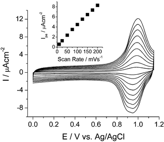
Electrochemical behavior of porphyrin multilayers was characterized by using cyclic voltammetry. For this study, ITO was used as the working electrode. TPP-SiCl2 undergoes two electron oxidations and two electron reductions at the porphyrin ring in an electrolyte of 0.1 M TBAPF6 in CH2Cl2.9 The monolayer of porphyrin-silicon complex showed a quasi-reversible first oxidation wave at 0.97 V (vs Ag/AgCl). The first oxidation can be attributed to the oxidation of the π ring system to form the π cation radical. However, the second oxidation process, observed at 1.36 V, was irreversible. The reversibility of the first oxidation process was tested in the potential range of −0.2 to 1.1 V. The oxidation potential and charge density remained unchanged after several scans. The total oxidation charge estimated by integration of the voltammetric peak was plotted against the number of layers (Fig. 2). The amount of redox-active porphyrins, proportional to oxidation charge, was increased rather linearly by the number of layers. This result is consistent with that of UV/Vis and confirms the reproducibility of the layer-by-layer immobilization approach. A slight deviation from linearity as the number of layers increases (fourth and fifth layers) was observed which might come from a rough surface of ITO as discussed earlier. It is noteworthy that the half wave of the oxidation of monolayer and five layers are almost identical, indicating that they are electrochemically equivalent (Supplementary Information†). The average density of charge involved in the oxidation in each layer deduced from the slope in the linear region (up to three layers) in Fig. 2 was 2.08 µC cm−2. Surface coverage of 2.16 × 10⁻¹¹ mol cm−2 or 1.30 × 10¹³ molecules cm−2 was calculated from the charge density.10 These values correspond to an effective area of 7.7 nm2 per molecule, larger than the unit cell calculated theoretically for a compact tetraphenylporphyrin monolayer (2.59 nm2).11 This modest surface coverage may be due to the fact that the immobilization process is driven by a kinetically controlled reaction between Si–OH and Si–Cl that prevents molecules from rearranging to find a more thermodynamically favorable well-packed monolayer. Fig. 3 displays the electrochemical behavior of five covalently attached layers of porphyrin modified ITO electrode at different scan rates in 0.1 M TBAPF6–CH2Cl2 without resistance compensation. It exhibited redox waves with formal potential at 0.97 V. The anodic peak currents were almost the same as the corresponding cathodic peak currents with small potential separation (ΔEp < 0.05 V). The anodic peak currents increased linearly with the scan rate between 10 and 200 mV s−1 as expected for a reversible surface-confined Faradaic process. The stability of cyclic voltammetric responses of the multilayers during repetitive cycling at different scan rates indicates that the assembly is stable.
 | ||
| Fig. 2 A plot of charge for the first oxidation at 0.97 V versus the number of layers. | ||
 | ||
| Fig. 3 Scan rate dependence of redox peak currents: scan rates are 10, 25, 50, 75, 100, 125, 150, 175, and 200 mV s−1. | ||
Surface morphology of the multilayers of porphyrin was investigated by tapping mode atomic force microscopy (AFM). The morphologies of glass substrate and 10 layers of porphyrin on glass substrate were nearly identical indicating that the porphyrin multilayers covered the substrate relatively homogeneously without forming aggregates (Supplementary Information†).
In summary, we have demonstrated a new, layer-by-layer strategy for the fabrication of cofacially stacked porphyrin multilayer with siloxane linkages from TPP-SiCl2. UV/Vis and electrochemical characterizations confirmed reproducibility and stability of the assembly. This approach can be utilized for immobilizing many of hexacoordinate silicon porphyrins or phthalocyanines with convenient structural variation for interesting electro-optical properties and modifying the surface properties of electrodes in organic semiconductor devices. The surface Si–OH or Si–Cl functionalities on the multilayers can be further used to anchor functional molecules for wide range of applications.
We gratefully acknowledge the financial supports of the National Science Foundation and the NSF MRSEC program at the University of Chicago. We also thank for partial supports UC-Argonne Nanoscience Consortium and UC/ANL collaborative seed grant.
Notes and references
- R. W. Murray, Molecular Design of Electrode Surfaces; Wiley, New York, 1992 Search PubMed.
- (a) K. M. Kane, F. R. Lemke and J. L. Petersen, Inorg. Chem., 1995, 34, 4085–4091 CrossRef CAS; (b) K. M. Kadish, Q. Y. Xu, J.-M. Barbe and R. Guilard, Inorg. Chem., 1998, 27, 1191–1198; (c) K. M. Kane, C. R. Lorenz, D. M. Heilman and F. R. Lemke, Inorg. Chem., 1998, 37, 669–673 CrossRef CAS; (d) J.-Y. Zheng, K. Konishi and T. Aida, Inorg. Chem., 1998, 37, 2591–2594 CrossRef CAS.
- (a) R. D. Joyner and M. E. Kenney, Inorg. Chem., 1962, 1, 717–718 CrossRef CAS; (b) M. K. Lowery, A. J. Starshak, J. N. Esposito, P. C. Krueger and M. E. Kenney, Inorg. Chem., 1965, 4, 128 CrossRef CAS; (c) J. B. Davison and K. J. Wynne, Macromolecules, 1978, 11, 186–191 CrossRef; (d) C. W. Dirk, T. I. Inabe, K. F. Schoch and T. J. Marks, J. Am. Chem. Soc., 1983, 105, 1539–1550 CrossRef CAS; (e) T. J. Marks, Science, 1985, 227, 881–889 CrossRef CAS; (f) E. Orthmann and G. Wegner, Makromol. Chem., Rapid Commun., 1986, 7, 243–247 CrossRef CAS; (g) W. Caseri, T. Sauer and G. Wegner, Makromol. Chem., Rapid Commun., 1988, 9, 651–657 CrossRef CAS.
- R. Šilerová, L. Kalvoda, D. Neher, A. Ferencz, J. Wu and G. Wegner, Chem. Mater., 1998, 10, 2284–2292 CrossRef CAS.
- (a) D.-J. Qian, C. Nakamura and J. Miyake, Chem. Commun., 2001, 2312–2313 RSC; (b) D.-J. Qian, C. Nakamura, T. Ishida, S.-O. Wenk, T. Wakayama, S. Takeda and J. Miyake, Langmuir, 2002, 18, 10237–10242 CrossRef CAS.
- K. Araki, M. J. Wagner and M. S. Wrighton, Langmuir, 1996, 12, 5393–5398 CrossRef CAS.
- D. Li, T. Buscher and B. I. Swanson, Chem. Mater., 1994, 6, 803–810 CrossRef CAS.
- (a) K. Chandrasekaran, C. Giannotti, K. Monserrat, J. P. Otruba and D. G. Whitten, J. Am. Chem. Soc., 1982, 104, 6200–6206 CrossRef CAS; (b) A. Tepore, A. Serra, D. P. Arnold, D. Manno, G. Micocci, A. Genga and L. Valli, Langmuir, 2001, 17, 8139–8144 CrossRef CAS; (c) T. Ogi, H. Ohkita, S. Ito and M. Yamamoto, Thin Solid Films, 2002, 415, 228–235 CrossRef CAS.
- C. R. Lorenz, H. D. Dewald and F. R. Lemke, J. Electroanal. Chem., 1996, 415, 179–181 CrossRef CAS.
- (a) R. W. Murray, in Electroanalytical Chemistry; A. J. Bard, Ed.; Marcel Dekker, New York, 1984; Vol. 13, pp. 191–368 Search PubMed; (b) H. O. Finklea, in Electroanalytical Chemistry; A. J. Bard and I. Rubinstein, ed.; Marcel Dekker, New York, 1996; Vol. 19, pp 109–335 Search PubMed.
- A. L. Bramblett, M. S. Boeckl, K. D. Hauch, B. D. Ratner, T. Sasaki and J. W. Rogers, Surf. Interface Anal., 2002, 33, 506–515 CrossRef CAS.
Footnotes |
| † Electronic supplementary information (ESI) available: detailed procedure for the assembly of porphyrin multilayers, experimental conditions for cyclic voltammetry, and AFM images of porphyrin multilayers. See DOI: 10.1039/b512084e |
| ‡ Present Address: Department of Chemistry, University of Nevada Las Vegas, 4505 Maryland Parkway, Box 454003, Las Vegas, Nevada 89154-4003. |
| This journal is © The Royal Society of Chemistry 2006 |
