Controlled formulation of monodisperse double emulsions in a multiple-phase microfluidic system
Takasi
Nisisako
*,
Shingo
Okushima
and
Toru
Torii
Department of Precision Engineering, Graduate School of Engineering, The University of Tokyo, 7-3-1 Hongo, Bunkyo-ku, Tokyo, Japan. E-mail: nisisako@intellect.pe.u-tokyo.ac.jp; Fax: 81-3-5841-6072; Tel: 81-3-5841-6072
First published on 15th April 2005
Abstract
This paper gives an overview of our recent work on the use of microfluidic devices to formulate double emulsions. Key issues in the controlled encapsulation of highly monodisperse drops include: (a) regular periodicity in the formation of micro droplets due to the interplay between viscous shearing and interfacial tension in low Reynolds number streams; (b) serially connected hydrophobic and hydrophilic microchannels to form aqueous and organic drops consecutively. Water-in-oil-in-water emulsions and oil-in-water-in-oil emulsions can both be produced by reversing the order of hydrophobic and hydrophilic junctions. Alternating formation of aqueous droplets at a cross junction has enabled the production of organic droplets that encase two aqueous droplets of differing compositions.
 Takasi Nisisako | Takasi Nisisako received his B.Eng. degree in 2000, M.Eng. degree in 2002 and Ph.D. degree in 2005 from the University of Tokyo, Japan. He is currently working as a post-doctoral researcher in the Department of Precision Engineering, Graduate School of Engineering, the University of Tokyo, Japan. His research interests include multiple-phase microfluidics, synthesis of complex colloids, micro-reactors, electronic papers and their industrial applications. |
 Shingo Okushima | Shingo Okushima was born in Tokyo, Japan, in 1978. He received his B.Eng. degree in 2003 and M.Eng. degree in 2005, both from the University of Tokyo. He is currently working at Canon Inc., Japan. His research interests include bio-MEMS, microfluidic systems and other MEMS applications. |
 Toru Torii | Toru Torii received a B.S. from the School of Agriculture of the University of Tokyo in 1980, and a M.S. from the School of Engineering, in 1982. From 1982 to 1984, he was a member of the technical staff of Mitsubishi Motors Corporation. From 1984 to 1989, he was an assistant professor in Tohoku Institute of Technology. From 1989 to 1999, he was an assistant professor with the Department of Agricultural Engineering in the University of Tokyo. In 1992, he received a Ph. D. from the University of Tokyo. Since 1999, he has been an associate professor with the Department of Precision Engineering, the University of Tokyo. His current research interests include microfluidic devices and lab on a chip devices. |
1. Introduction
Double emulsions are complex soft colloidal systems in which droplets of the dispersed phase themselves contain even smaller droplets.1,2 Typical examples are water-in-oil-in-water (W/O/W) and oil-in-water-in-oil (O/W/O). These are thermodynamically stabilized by a set of lipophilic and hydrophilic surfactants dissolved in the intermediate phase and the external phase.Various industries, including cosmetics,3 foods4 and pharmaceuticals,5 are showing increasing interest in these systems, because of their potential for the controlled release of chemical substances initially entrapped in the internal phase. Major applications studied to date include pharmaceuticals using W/O/W emulsions, which act as a carrier of water-soluble drugs for sustained release or targetable delivery.6–9 Biodegradable solid capsules loading bioactive agents such as hormones,10 peptides11 and oligonucleotides12 have also been prepared for medical use. Other applications of double emulsions include the synthesis of composite microspheres by suspension polymerization,13 and the separation of hydrocarbons,14 metals15 and organic acids16 by a liquid membrane of the intermediate phase.
The two-step emulsification process17 is now widely used in the practical production of double emulsions. For W1/O/W2 emulsions, the primary W1/O emulsion is prepared under vigorous stirring or sonication. This dispersion is then poured into the intended external aqueous phase (W2), and secondary mixing is conducted at lower shear to prevent disruption of the prepared capsules. Problems associated with this method include a broader size distribution, poor controllability and reproducibility of the droplet size, and low entrapment yield. All are due to the turbulent shear occurring in the process. Recently the membrane-emulsification technique18,19 has been applied to formulate monodisperse double emulsions by forcing single emulsions through porous media20 or microfabricated combs.21,22 This technique can produce double emulsions with narrower size distribution and higher entrapment yield, but it is still difficult to achieve good control over the internal droplet size, external droplet size and the number of droplets contained in each capsule. Moreover, the techniques stated usually consist of two separate batch processes, limiting the production efficiency. Other techniques such as phase inversion23,24 and capillary jet methods25,26 share the limitations described above.
Here, we present a new method for preparing double emulsions using microfluidic systems that have already shown promise in creating micro droplets of controlled sizes.27–34Fig. 1 shows our method for producing W/O/W emulsions.35 Aqueous droplets of uniform size are formed reproducibly within an organic flow at the upstream T-junction. This stream then flows into the second T-junction, to create monodisperse organic droplets containing aqueous droplets within an external aqueous phase. The size and breakup rate of the droplets can be flexibly controlled by varying the flow conditions at each junction. The number of encased droplets can be accurately determined by adjusting the relation between the breakup rates at the two junctions. Similarly, O/W/O emulsions can be produced when the hydrophobic junction is prepared downstream.
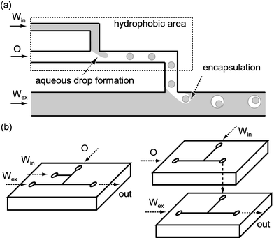 | ||
| Fig. 1 (a) Schematic diagram of the formation of a W/O/W double emulsion; (b) one-chip module (left) and two-chip module (right). Win: internal aqueous phase. O: intermediate organic phase. Wex: external aqueous phase. | ||
2. Fabrication of microchannels and device configuration
The choice of material for a droplet-generating device is important, because the wetting of the channel surface determines the type of dispersion that can be prepared. Channels fabricated on hydrophobic materials such as poly(dimethylsiloxane) (PDMS)29,31,34 and poly(methyl methacrylate) (PMMA)28 are preferable for lab-on-a-chip applications since their water-repellent surface is necessary for aqueous drop preparation. On the other hand, the hydrophilic surface of glass is suitable for organic droplets; an example is the preparation of monomer droplets for the synthesis of polymeric microspheres having narrow size distribution.33 For producing double emulsions, hydrophobic and hydrophilic components are both necessary, as shown in Fig. 1. We chose glass in order to fabricate those channels, because its surface is intrinsically hydrophilic but can be made hydrophobic by methods such as siliconization, silanization and coating with amorphous fluoropolymers.32,36 Mechanical machining, isotropic wet etching and anisotropic dry etching were used for fabricating channels with cross-sectional dimensions in the range 40–200 µm.Two configurations are proposed for the production of double emulsions: a one-chip module in which the hydrophobic junction and the hydrophilic junction are on the same plate, and a two-chip module in which these junctions are on separate chips (Fig. 1b). In a one-chip module, one of the two junctions was made hydrophobic by introducing a reagent for surface modification, whereas in a two-chip module the entire channels were modified in either of the two chips. Localized surface modification in a one-chip module for W/O/W emulsions was conducted as follows. A water-soluble siliconizing fluid was diluted with deionized water, and this solution was introduced into the microfluidic channel to make the entire internal surface hydrophobic. Sodium hydroxide solution (2 mol l−1) was then infused into the channel from the inlet for the external aqueous phase in order to remove the hydrophobic layer, so that the hydrophilic surface is produced around the downstream junction. During this process, immiscible organic fluid was infused from the inlets for the internal or intermediate phase, which filled up the channels around the upstream junction. This prevents the sodium hydroxide solution from flowing back into the intended hydrophobic upstream junction.
3. Formation of double emulsions
Fig. 2 shows the formation of W/O/W droplets in a one-chip module. An array of monodisperse aqueous droplets (diameter 52 µm, coefficient of variation (CV) 2.7%) was formed within the stream of the organic phase (corn oil) at the hydrophobic T-junction. This array of droplets was carried to the downstream hydrophilic junction, with the droplets remaining a uniform distance from each other. Each aqueous droplet was then reliably encased within an organic droplet (diameter 83 µm, CV 2.8%) as the stream of the water-in-oil dispersion was sheared into the stream of the external aqueous phase. By slight adjustment of the flow conditions it was also possible to create ellipsoidal organic drops enclosing two aqueous drops (Fig. 2c), which can scarcely be obtained by conventional techniques. Such monodisperse ellipsoids may be used for packing at higher volume fractions.37 The deformed shape of the internal drops suggests that multiple drops could be encased with higher entrapment yield using the microfluidic approach. Two-chip modules could also be employed for the preparation of monodisperse W/O/W droplets. However, the number of internal droplets was less uniform, because the stable array of to-be-enclosed droplets formed in the upstream chip was broken when these droplets reached the downstream junction. This is because of the sudden change in flow speed at the connecting area (a hole of diameter 0.5–1.0 mm) between the two chips. A smoother connection between the two chips would allow more precise control of the encapsulation.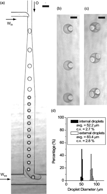 | ||
| Fig. 2 (a) Photomicrograph of droplet formation at two consecutive T-junctions. The breakup rate at each junction is ∼22 drops s−1. (b, c) The generated W/O/W droplets observed in the microfluidic device. (d) Size distribution of internal aqueous droplets and external organic droplets. The scale bars are (a) 100 µm, (b, c) 50 µm. Win: deionized water, O: corn oil containing lipophilic surfactant, Wex: aqueous solution of hydrophilic surfactant. | ||
The internal and external drop sizes and the number of encased drops were controlled by varying the flow rates of the individual streams. As an example, Fig. 3 shows the variation of the external drop size and the number of enclosed drops as the flow rate of the external phase varies. As the flow rate of the external phase is increased, the size of the external drops decreased from 210 to 150 µm. This reduction implies an increase in the breakup rate at the second junction, reducing the number of internal drops (from 4.3 to 1.4). Similarly, the streams of the internal phase and the intermediate phase can be used to determine the drop-in-drop structure.
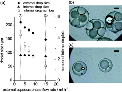 | ||
| Fig. 3 Effect of the flow conditions of the external aqueous phase on the formation of W/O/W emulsion. (a) Variation of the internal drop size, external drop size and the number of enclosed drops. (b) W/O/W droplets formed in condition (1) in the graph. (c) W/O/W droplets formed in condition (2). The scale bars are 50 µm. Win: deionized water, O: corn oil containing lipophilic surfactant, Wex: aqueous solution of hydrophilic surfactant. | ||
Coalescence of the resulting capsules was prevented by surfactants added to the intermediate phase and the external phase. Fig. 4 shows various W/O/W emulsions in which the number of internal drops was precisely controlled. All of these dispersions, including non-spherical ones (Fig. 4b), were perfectly stable at room temperature (20 ± 1 °C) for at least one month. A study of stability over longer timescales is under way.
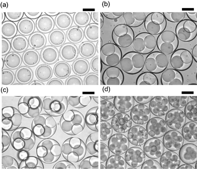 | ||
| Fig. 4 Stable W/O/W emulsions with a controlled number of internal droplets (n). (a) n = 1. (b) n = 2. (c) n = 4, (d) n = 8. All are stored at room temperature (20 °C). The scale bars are 100 µm. Win: deionized water, O: decane containing lipophilic surfactant, Wex: aqueous solution of hydrophilic surfactant. | ||
We further developed the method to formulate capsules that contain multiple internal droplets with differing compositions. Zheng et al. used a cross-shaped channel to produce an array of droplets of alternating composition suitable for droplet-based bioassays.38,39 They characterized the fluid condition for reliable formation of stable alternating droplets by the capillary number (Ca): Ca = Uη/γ, where U is the velocity of the continuous phase stream, γ is the interfacial tension between two immiscible liquids, and η is the viscosity of the continuous phase.39 The optimal Ca range for successful alternating droplet formation was found to be 0.001 < Ca < 0.15. We arranged a hydrophobic cross-shaped geometry as the upstream junction so as to generate the array of to-be-enclosed aqueous droplets from differing sources (Fig. 5a). Red and blue aqueous drops of similar size were formed alternately when the organic stream was in the right flow condition (Ca ∼ 0.08), and the arrayed droplets flew into the second junction to be jointly packed into organic droplets (Fig. 5b,c). The droplet size and breakup rate can be varied via the flow conditions, so that multiple droplets supplied from different sources can be encapsulated with the desired volume fractions.
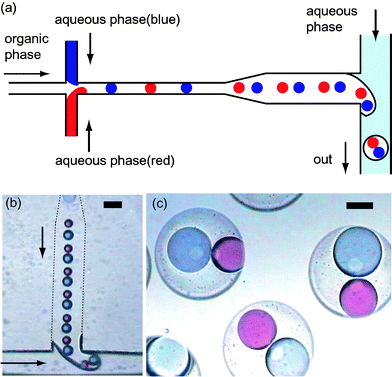 | ||
| Fig. 5 (a) Schematic diagram of the alternating formation of aqueous droplets at the upstream junction and subsequent encapsulation at the downstream junction. (b) Photograph of formation of an oil droplet enclosing blue and red droplets. (c) Photograph of the prepared W/O/W droplets. The diameter of the external drop is 175 µm. The scale bars are (b) 100 µm, (c) 50 µm. Win: deionized water, O: corn oil containing lipophilic surfactant, Wex: aqueous solution of hydrophilic surfactant. | ||
4. Conclusions and outlook
Our microfluidic approach has enabled the formulation of well-calibrated monodisperse double emulsions. Surface modification of the upstream junction enabled the formation of W/O/W emulsions, whereas O/W/O emulsions were produced when the hydrophobic junction is prepared downstream. The internal drop size, the external drop size, and the number of encased droplets were accurately controlled by varying the flow conditions. Two aqueous drops of distinct solutions may be encased in a single oil droplet by introducing a cross-shaped channel as the upstream component.An important issue in the formulation of double emulsions is the size of the external droplet. So far we have achieved droplet sizes in the range 40–200 µm, similar to the cross-section dimensions of the channels used. With smaller microchannels, capsules as small as 10 µm might be formulated, significantly widening the area of application; examples include model systems for cell-like environments40 and drug carriers for intravascular use. Such small channels have drawbacks, however. They are more susceptible to blockages, so that the raw materials to formulate double emulsions might be limited. Greater flow resistance would make it more difficult to infuse viscous fluids. Optimization of the channel geometry—the aspect ratio and channel length—is then vital. A further critical issue is the productivity scale-up needed for practical industrial applications. Some 103–104 channels would be needed for a production rate as high as 1 kg h−1, since the maximum throughput per unit is presently ∼1 g h−1. Although such large-scale integration of microchannels can be realized by conventional lithographic techniques, it remains unclear whether fluid can be supplied equally into every channel so as to produce uniform-sized droplets in parallel. This issue must be investigated together with the construction of piled up systems of multiple modules for further scale-up. In view of the parallelization of many channels that is involved, the two-chip module mentioned above is better suited, because localized surface modification as in the one-chip module is not necessary.
The methodology described here could greatly increase the range of applications of double emulsions. Droplets of defined sizes and well-controlled entrapment yield can act as ideal model systems to give a better understanding of release properties and stability conditions. Polymerization of ellipsoidal double-emulsion droplets might be able to produce monodisperse non-spherical particles. The close packing of internal drops may be valuable for structuring three-dimensional colloidal assemblies having spherical shape.41,42 Furthermore, organic drops containing multiple aqueous drops of differing compositions may be utilized in multiplexed assays for screening applications.43
References
- A. T. Florence and D. Whitehill, Int. J. Pharm., 1982, 11, 277 CrossRef CAS.
- N. Garti, Colloids Surf. A, 1997, 123–124, 233 CrossRef CAS.
- K. Yoshida, T. Sekine, F. Matsuzaki, T. Yanaki and M. Yamaguchi, J. Am. Oil Chem. Soc., 1999, 76, 195 CAS.
- S. Matsumoto, J. Texture Stud., 1986, 17, 141 Search PubMed.
- S. S. Davis and I. M. Walker, Methods Enzymol., 1987, 149, 51 CAS.
- W. J. Herbert, Lancet, 1965, 286, 771 CrossRef.
- R. Engel, S. J. Riggi and M. J. Fahrenbach, Nature, 1968, 219, 856 CAS.
- P. A. Gresham, M. Barrett, S. V. Smith and R. Schneider, Nature, 1971, 234, 149 CAS.
- S. Higashi and T. Setoguchi, Adv. Drug Delivery Rev., 2000, 45, 57 CrossRef CAS.
- Y. Ogawa, M. Yamamoto, H. Okada, T. Yashiki and T. Shimamoto, Chem. Pharm. Bull., 1988, 36, 1095 CAS.
- P. Couvreur, M. J. Blanco-Prieto, F. Puisieux, B. Roques and E. Fattal, Adv. Drug Delivery Rev., 1997, 28, 85 CrossRef CAS.
- T. Freytag, A. Dashevsky, L. Tillman, G. E. Hardee and R. Bodmeier, J. Controlled Release, 2000, 69, 197 CrossRef CAS.
- G.-H. Ma, H. Sone and S. Omi, Macromolecules, 2004, 37, 2954 CrossRef CAS.
- N. N. Li, AIChE J., 1971, 17, 459 CrossRef CAS.
- L. Boyadzhiev and E. Bezenshek, J. Membrane Sci., 1983, 14, 13 CrossRef CAS.
- C. D. Cerro and D. Boey, Chem. Ind., 1988, 7, 681 Search PubMed.
- S. Matsumoto, Y. Kita and D. Yonezawa, J. Colloid Interface Sci., 1976, 57, 353 CrossRef CAS.
- T. Nakashima, M. Shimizu and M. Kukizaki, Adv. Drug Delivery Rev., 2000, 45, 47 CrossRef CAS.
- S. van der Graaf, C. G. P. H. Schroën and R. M. Boom, J. Membrane Sci., 2005 Search PubMed , in press.
- Y. Mine, M. Shimizu and T. Nakashima, Colloids Surf. B, 1996, 6, 261 CrossRef CAS.
- T. Kawakatsu, G. Trägårdh and C. Trägårdh, Colloids Surf. A, 2001, 189, 257 CrossRef CAS.
- S. Sugiura, M. Nakajima, K. Yamamoto, S. Iwamoto, T. Oda, M. Satake and M. Seki, J. Colloid Interface Sci., 2004, 270, 221 CrossRef CAS.
- W. Seifriz, J. Phys. Chem., 1925, 29, 738 CrossRef.
- P. Dokic and P. Sherman, Colloid Polym. Sci., 1980, 258, 1159 CrossRef CAS.
- D. P. Kessler and J. L. York, AIChE J., 1970, 16, 369 CrossRef CAS.
- I. G. Loscertales, A. Barrero, I. Guerrero, R. Cortijo, M. Marques and A. M. Gañán-Calve, Science, 2002, 295, 1695 CrossRef CAS.
- T. Thorsen, R. W. Roberts, F. H. Arnold and S. R. Quake, Phys. Rev. Lett., 2001, 86, 4163 CrossRef CAS.
- T. Nisisako, T. Torii and T. Higuchi, Lab Chip, 2002, 2, 24 RSC.
- S. L. Anna, N. Bontoux and H. A. Stone, Appl. Phys. Lett., 2003, 83, 364 CrossRef CAS.
- R. Dreyfus, P. Tabeling and H. Willaime, Phys. Rev. Lett., 2003, 90, 144505 CrossRef.
- J. D. Tice, H. Song, A. D. Lyon and R. F. Ismagilov, Langmuir, 2003, 19, 9127 CrossRef CAS.
- K. Martin, T. Henkel, V. Baier, A. Grodrian, T. Schön, M. Roth, J. M. Köhler and J. Metze, Lab Chip, 2003, 3, 202 RSC.
- T. Nisisako, T. Torii and T. Higuchi, Chem. Eng. J., 2004, 101, 23 CrossRef CAS.
- Y. C. Tan, J. S. Fisher, A. I. Lee, V. Cristini and A. P. Lee, Lab Chip, 2004, 4, 292 RSC.
- S. Okushiima, T. Nisisako, T. Torii and T. Higuchi, Langmuir, 2004, 20, 9905 CrossRef.
- P. G. De Gennes, F. B. Wyart and D. Quere, Capillarity and Wetting Phenomena Drops, Bubbles, Pearls, Waves, Springer, New York, 2004, p. 25 Search PubMed.
- D. A. Weitz, Science, 2004, 303, 968 CrossRef CAS.
- B. Zheng, J. D. Tice, L. S. Roach and R. F. Ismagilov, Angew. Chem., Int. Ed., 2004, 43, 2508 CrossRef CAS.
- B. Zheng, J. D. Tice and R. F. Ismagilov, Anal. Chem., 2004, 76, 4977 CrossRef CAS.
- D. S. Tawfik and A. D. Griffiths, Nature Biotechnol., 1998, 16, 652 CrossRef CAS.
- O. D. Velev, A. M. Lenhoff and E. W. Kaler, Nature, 2000, 287, 2240 CrossRef CAS.
- G. R. Yi, T. Thorsen, V. N. Manoharan, M. J. Hwang, S. J. Jeon, D. J. Pine, S. R. Quake and S. M. Yang, Adv. Mater., 2003, 15, 1300 CrossRef CAS.
- J. P. Nolan and L. A. Sklar, Trends Biotechnol., 2002, 20, 9 CrossRef CAS.
| This journal is © The Royal Society of Chemistry 2005 |