Modeling the flow of complex fluids through heterogeneous channels
Anna C.
Balazs
*,
Rolf
Verberg
,
Christopher M.
Pooley
and
Olga
Kuksenok
Chemical Engineering Department, University of Pittsburgh, 1248 Benedum Hall, 3700 O'Hara Street, Pittsburgh, PA 15261, USA. E-mail: balazs1@engr.pitt.edu
First published on 21st April 2005
Abstract
Computational modeling of the driven flow of multi-component fluids past chemically, physically and thermally heterogeneous substrates can provide insight into a variety of processes, from flow in microfluidic devices to polymer processing in reaction chambers. One of the challenges in modeling these systems is capturing the close interplay between hydrodynamics and thermodynamics. The lattice Boltzmann method (LBM) provides a computationally efficient method for carrying out such investigations. We review recent studies using the LBM to examine the flow of partially miscible binary fluids through channels that contain chemically, topographically or thermally patterned substrates. The findings highlight how the substrates can be modified to yield the required behavior at fluid/surface and fluid/fluid interfaces and consequently, the desired macroscopic properties. Specifically, the results provide guidelines for optimizing processes in microfluidic devices and in creating microemulsions with well-controlled morphologies. The studies also reveal new phenomena that arise from the interplay between flowing complex fluids and chemically, physically and thermally patterned confining walls.
 Anna C. Balazs | After obtaining her undergraduate degree in physics from Bryn Mawr College, Anna Balazs received her Ph.D. in Materials Science in 1981 from the Massachusetts Institute of Technology. She then carried out postdoctoral research in polymer science at the University of Massachusetts, Amherst. She is currently the Robert von der Luft Professor and Distinguished Professor of Chemical Engineering in the Chemical Engineering Department at the University of Pittsburgh. Her research interests involve modeling the properties of complex fluids, polymer blends, nanocomposites, and fluid–structure interactions in biological systems. |
 Rolf Verberg | Rolf Verberg received his PhD in Physics at Delft University of Technology, The Netherlands in October 1998. He was a Postdoctoral Researcher at the University of Florida from 1998 to 2001, at Cornell University from 2001 to 2003, and joined Prof. Balazs's group in 2003. His current interests include the dynamics of multiphase flows in complex geometries and the coupled dynamics of fluid–solid systems with a compliant interface. |
 Christopher M. Pooley | Christopher Pooley completed his Masters Degree in Physics at the University of Oxford, UK in 2000. He subsequently received a PhD at the same university in 2003, for work on complex fluids under the supervision of Prof. Julia Yeomans. He then joined Prof. Balazs's group, where his current research interests include novel pattern formation in multi-component fluids, and co-operative phenomena in biological cell systems. |
 Olga Kuksenok | Olga Kuksenok graduated from Kiev State University and received her PhD in Physics and Mathematics in 1997 at the Institute of Physics, Ukrainian Academy of Sciences, Kiev, Ukraine. Currently, she is a Postdoctoral Research Associate at the University of Pittsburgh, Chemical Engineering Department. Her research is focused on theory and computer simulations of complex multi-component fluids. |
Introduction
From optimizing the processing of polymeric materials to controlling blood flow in natural or synthetic channels, it is vital to understand the dynamic behavior of complex fluids in confined geometries. Developing such an understanding is complicated by the fact that in the systems of interest, the confining walls can display chemical or physical heterogeneities and the fluid usually contains multiple components. Furthermore, this multi-component mixture is driven by an imposed flow (which transports the fluid through the processing chambers or the blood vessels). In these complex systems, the fluid–wall and fluid–fluid interactions play critical roles in shaping the morphology and phase behavior of the confined mixture.Computational modeling can play an important role in enhancing our understanding of the dynamic behavior of complex fluids in heterogeneous channels. In particular, through a coupling of theory and simulation, one could systematically vary the fluid–wall and fluid–fluid interactions and thereby pinpoint how these interactions contribute to the observed macroscopic behavior. Ultimately, these findings can indicate how to manipulate the nature of the walls to control the behavior of multi-component flows.
One challenge in carrying out such studies is capturing all the relevant interactions, including the hydrodynamic interactions, within computationally realistic timeframes. Atomistic approaches, such as molecular dynamics (MD) simulations, are too computationally intensive for determining the long-time flow behavior of multi-component mixtures in chemically or physically patterned chambers. Other possible approaches include more conventional computational fluid dynamics methods, which involve a direct discretization and numerical solution of the Navier–Stokes equation. In these approaches, however, the introduction of chemically or physically varying boundary conditions at the confining surfaces generally entails ad hoc assumptions and increased computational time.
One means of resolving these computational issues is to use numerical approaches that are loosely categorized as “mesoscale” simulations, such as the lattice Boltzmann model (LBM). Through these approaches, one can describe hydrodynamic time scales and sufficient microscopic information to capture the ordering and flow properties of multi-component fluids in complex environments. In this review, we highlight recent studies using the LBM to model the flow of binary fluid mixtures in confined geometries, where the confining walls exhibit variations in chemistry and architecture. We describe results on pressure driven flow of two partially miscible fluids, A and B, through a microchannel that is decorated with A-like and B-like patches on the underlying substrates.1,2 Due to these patches, the two fluids can be driven to undergo extensive mixing within specific regions of the channel. We also consider the flow of the AB fluid through microchannels whose top and bottom surfaces contain regularly spaced “teeth” or asperities, which have a preferential wetting interaction with one of the fluids.3 As will be shown, the results from the latter investigations provide guidelines for creating emulsions that contain monodisperse droplets; such emulsions are vital in the pharmaceutical, food and cosmetic industries. A specific motivation for considering the topographically patterned surfaces comes from advances in microfabrication that have permitted the production of physically patterned surfaces with spatially regular, micron-scale features.4 In order to optimize the use of these substrates in microfluidic devices, ink-jet printing5 and the formulation of microemulsions, it is essential to determine how flowing fluids interact with such topographically patterned surfaces.
We also describe a scenario where the confining walls exhibit variations in temperature. By introducing thermal variations, we can investigate the role of one of the most important processing variables (namely, temperature) on the structural evolution and phase behavior of the confined complex fluids. Variations in temperature become even more crucial when they encompass the critical temperature of the binary fluid, so that the system undergoes a phase transition from a single-phase fluid to a two-phase mixture. Here, we focus on a particular system where a phase-separating AB binary fluid is confined between two plates, where the bottom plate is hot and is above the fluid's critical temperature, Tc, while the top plate is cold and lies below Tc. In this scenario, the interplay between convection and phase separation leads to complex dynamical behavior.6
Overall, the findings reveal a rich phase behavior that emerges when multi-component fluids are driven to flow between heterogeneous surfaces. Before describing the specific studies, we first provide a brief overview of the lattice Boltzmann approach, starting with the underlying governing equations. For more detailed descriptions of this technique, we refer the reader to references 7–10. We then describe how this approach is implemented to examine the systems of interest.
Methodology
We begin by describing our approach in its most general form. We then detail the specific extensions that are required to model the chemical/physical patterning of the surface and the presence of temperature gradients. The equilibrium free energy for the system serves as the starting point for our description of the system. For an AB binary fluid, this free energy is given by:11,12 | (1) |
 | (2) |
The dynamics of the fluid is described by the Navier–Stokes equations. The exact form of these equations will depend on the system to be considered. For example, for an isothermal binary fluid, they are:
 | (3) |
 | (4) |
 | (5) |
The boundary conditions on the velocity field are typically taken to be no-slip. The boundary conditions on the order parameter follow directly from minimizing the free energy in eqn. (1); using the Cahn expression this gives:
 | (6) |
The above evolution equations (eqn. (3)–(5)) are solved using a lattice Boltzmann algorithm. This is an efficient Navier–Stokes solver that is well suited to parallel coding and is able to handle boundaries with non-trivial topography with relative ease. In the subsequent section, we provide a brief description of this approach.7–10
Lattice Boltzmann method
Unlike the traditional computational fluid dynamics approach, which involves a numerical solution of the discretized Navier–Stokes equation, the lattice Boltzmann method (LBM) involves a mesoscale simulation of the Navier–Stokes equation. (We use the term mesoscale to represent a length scale in between those of atomistic systems and macroscopic continuum systems.) The LBM simulations consist of two processes, the first being the collision of fluid “particles” at each lattice site, and the second being the propagation of these “particles” to neighboring sites. Here, fluid “particles” are representative of mesoscopic portions of the fluid, and are described by particle distribution functions.The particle distribution functions nα(r, ci, t) describe the mass density of fluid particles of component α at a lattice node r with a velocity ci at time t. For a binary fluid, the state of the system is characterized by the total mass density, ρi(r, t) = nA(r, ci, t) + nB(r, ci, t), and the density difference, or order parameter, ϕi(r, t) = nA(r, ci, t) − nB(r, ci, t). In two dimensions, the “9-speed model”, which includes the zero-velocity case (rest-particles), is used to model the movement of particles along vectors that connect nearest and next-nearest neighbors on a square lattice. Correspondingly, in three dimensions, the “19-speed model” is used to model particle motion on a cubic lattice. The conserved quantities, mass density ρ(r, t), momentum density j(r, t), and order parameter ϕ(r, t), are moments of the distribution functions;
| ρ(r, t) = Σiρi(r, t) | (7) |
| j(r, t) = Σiciρi(r, t) | (8) |
| ϕ(r, t) = Σiϕi(r, t) | (9) |
The time-evolutions of ρi(r, t) and ϕi(r, t) are governed by the single relaxation-time lattice Boltzmann equations,
| ρi(r + ci, t + Δt) = ρi(r, t) − (ρi(r, t) − ρeqi(r, t))/τρ | (10) |
| Σiciciρeqi = P + ρuu | (11) |
| Σiciciϕeqi = ΓμI + ϕuu | (12) |
 | (13) |
![[small phi, Greek, tilde]](https://www.rsc.org/images/entities/i_char_e0e2.gif) (s) is set to the value of the order parameter for the pure A (B) phase, i.e., (s)
=
ϕA(B). We emphasize that such a description is necessary for relatively long-range interactions; for short-range interactions, the bulk contribution can be neglected and the presence of the chemically modified patches can be accounted for through an appropriate boundary condition at the solid–fluid interface (as given, for example, by eqn. (6)).
(s) is set to the value of the order parameter for the pure A (B) phase, i.e., (s)
=
ϕA(B). We emphasize that such a description is necessary for relatively long-range interactions; for short-range interactions, the bulk contribution can be neglected and the presence of the chemically modified patches can be accounted for through an appropriate boundary condition at the solid–fluid interface (as given, for example, by eqn. (6)).
 | (14) |
The dynamics of this system is determined by:6
 | (15) |
 | (16) |
 | (17) |
 | (18) |
 | (19) |
We no longer assume that temperature is constant across the system. Eqn. (17) expresses energy conservation. The internal energy per unit volume is related to the temperature by ρε = cvρkBT/m + λ(ρ2 − ϕ2), where cv = 3/2 is the specific heat per particle at constant volume. The first term comes from equipartition of energy, and the second comes from the potential energy associated with the repulsive interaction λ. Hence, there is a latent heat associated with transformations between the phase-separated and homogeneous states.
In the most general terms, the thermal flux, q, in eqn. (17) can be written as:19
 | (20) |
Results and discussion
Chemically patterned surfaces
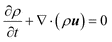
One of the challenges in carrying out reactions within microchannels is driving fluids to mix at the low Reynolds numbers that characterize flow in such small dimensions. To address this challenge, we examined how the introduction of “chemical patterns” on the walls of the microchannel could be harnessed to promote the intermixing of the components. In particular, for two streams of partially miscible fluids, A and B, we hypothesized that the presence of A-like and B-like regions on the substrates could be used to effectively “steer” the fluids and thereby enhance the degree of mixing in the system. (Here, the A-like patches are preferentially wet by the A fluid and similarly, the B-like patches are wet by the B component.) We varied the arrangements of these A-like and B-like patches to investigate how competition between the advection from the imposed flow (which drives the fluids through the channel) and the preferential interactions at the patches affects the motion and steady-state morphology within these channels.1,2,15–18In the first set of studies,1,2 we examined the pressure driven flow of a binary fluid in a two-dimensional microchannel over the patterned substrate shown schematically in Fig. 1(a). We assume no-slip boundary conditions for the velocity on the channel walls (the walls here are the top and bottom lines in the schematic in Fig. 1(a)). We also assume that the walls are impermeable (no flux of the fluids through the walls) and neutral (no preferential wetting of any component on the walls). The initial conditions for the order parameter distribution were chosen such that a stream of A flows parallel to a stream of B through the channel (see left edge of Fig. 1(a)). Here, blue corresponds to the A phase, and yellow marks the B phase. The chemical patches illustrated in Fig. 1(a) were introduced into the free energy in a way similar to eqn. (13), which in general allows us to specify the surface patterns and the range of the fluid–surface interactions (for details concerning the interaction potential, as well as details of the 2D simulations, see references 1 and 2). In this 2D study, we first placed a B-like patch in the path of the A stream and an A-like patch in the way of the B stream. In the adjacent layer, the positions of the patches were reversed, so that the entire pattern resembles a 2 × 2 checkerboard. Experimentally such chemically distinct regions can be created through microcontact printing21 or a combination of photolithography and self-assembled monolayer chemistry.22
 | ||
| Fig. 1 (a) Schematic of the 2D microchannel with chemically patterned checkerboard region. (b) Order parameter distribution and velocity profile within the patterned region. The fluid parameters are M = 0.3, λ = 4.4, η = 0.1, T = 0.5, κ = 0.01; the imposed pressure gradient is ∇P = 4 × 10⁻⁵. The bulk free energy is given by eqn. (14), and the interaction with the substrate is implemented in manner indicated by eqn. (13) (details can be found in ref. 1). | ||
The fluid is advected through the channel by an imposed Poiseuille flow. Due to the imposed flow, each component is pushed into the energetically unfavorable (or non-wettable) domains. The system tries to minimize its free energy by having the A-stream flow across the channel to the A-patch and the B-stream traverse the channel to the B-patch. This flow pattern is illustrated in Fig. 1(b), where the black arrows mark the direction the velocity field and the size of the arrow is proportional to the magnitude of the velocity.
As a consequence of this energy-minimizing process, the two components are driven to flow into each other and thereby undergo mixing. It is this effective coupling of thermodynamics and hydrodynamics that locally alters the phase behavior of the fluid. Fig. 1(b) shows that this mixing occurs in a relatively broad region between the patches. Here, the pink areas correspond to the mixed region, or the region where the order parameter is close to zero. As the fluids approach the second set of patches, they are once more confronted with energetically unfavorable regions. The arrows in Fig. 1(b) indicate that each component is again driven across the channel to reach its favorable domain. Fig. 1(b) also shows that the second set of patches contributes to enhancing the size of the mixed region in the system. We extended this study to three dimensions and found that the A/B checkerboard pattern provides the most effective mixing mechanism for channels with low height-to-width aspect ratios.15
These findings show how the flow field and behavior of multi-component fluids can be manipulated by the presence of patterned substrates, providing an effective, non-mechanical means of mixing the components. The results also highlight means of creating spatially localized reaction chambers within microfluidic devices.
We also examined how the arrangement of the different patches affects the flow patterns in three-dimensional channels.16–18 In these studies, we used a cell dynamical systems method23 to simulate the evolution of the order parameter (eqn. (5)), and adopted the Chebyshev–Tau spectral method24 to solve the Navier–Stokes equation (eqn. (4)) in the overdamped limit, together with the incompressibility condition. In the simplest case, a single B patch across the top and A patch across the bottom of the microchannel were found to switch the relative orientation of the two-stream flow from vertical to essentially horizontal.16 When both A and B patches are placed on the top and bottom surfaces, the system exhibits a temporally periodic state, where the A and B fluids become intertwined.17 Finally, when the top and bottom surfaces of the channel display a checkerboard pattern of A and B patches, monodisperse droplets of both A-in-B and B-in-A are formed simultaneously and periodically in time within the microchannel.18
Overall, these results indicate that the introduction of chemical patches on the flat walls of microchannels can be exploited to control the flow and morphology of binary fluids in the system. Furthermore, they show that chemically patterned substrates can be utilized to create the desired behavior without expending a significant amount of mechanical energy.
Chemically and physically patterned surfaces
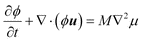
Having examined binary fluid flow past chemically patterned, flat surfaces, we then investigated how both chemical and topological patterning could be harnessed to direct the flow in the microchannels. One can envision that the polymeric stamps used in microcontact printing could be used to create such chemically and physically patterned walls. Considerable advances have been made in fashioning stamps with a wide variety of controlled architectures4 and thus, the protruding three-dimensional “teeth” can have columnar, conical or rectangular shapes. Furthermore, the bottom of the teeth can be chemically distinct from the rest of the walls. This can be accomplished experimentally in two ways: either the stamp is dipped in a solution in such a manner that only the long teeth touch and are coated with the fluid, or a solution is allowed to coat the entire stamp, after which the fluid layer at the bottom of the teeth is removed in the process of printing. In both cases, the stamps are both chemically and architecturally patterned in a well-controlled manner. It is these highly heterogeneous surfaces that we imagine as making up the top and bottom walls of our microchannel. We note that, depending on our choice of variables in the LBM, we can examine surface features that range in the 10's of nanometers to micron size scale.2,3,18 The model can also be used to mimic the behavior at larger length scales;3 we return to this point at the end of this discussion.In these studies of chemically and physically patterned surfaces, we focused on the shear-driven flow of immiscible, binary AB fluids in the system shown in Fig. 2. Here the walls display a regular array of square asperities, and the A phase is shown in red, while the B fluid is marked in blue. W gives the width of each asperity and B is the height; for these square asperities, W = B. We then varied the ratio W/H, where H denotes the non-obstructed gap height, or the height of the free channel between the asperities. The length L of the simulation box in the flow direction is fixed at 1024 lattice sites, H = 128 sites and U, the imposed velocity difference between the top and bottom wall, is set at 0.02. Here, we used the bulk free energy expression given by eqn. (2), with a = b = 1, and κ = 0.04. The mean density 〈ρ〉 = 1, while M = 1, and η = 1/6.
 | ||
| Fig. 2 Snapshots of the order parameter distribution for two-dimensional shear flow between walls with a regular array of square asperities and an initially banded morphology; (a) initial order parameter distribution (for W/H = 1/2); (b) final state for W/H = 1/4, (c) final state for W/H = 1/2, and (d) tγ = 2.73 for W/H = 1. | ||
Fig. 2 shows snapshots of the system for three different ratios, W/H = 1/4, 1/2, and 1 and square asperities that are separated by a distance G, which is equal to the bandwidth. The initial order parameter distribution is shown in Fig. 2(a). There is a critical W/H ratio below which the system evolves to a final steady-state: a single band of A in the center of the gap for W/H = 1/4 (Fig. 2(b)) and an array of A droplets in the center of the gap for W/H = 1/2 (Fig. 2(c)). Above the critical ratio, the system evolved to a state in which bands break up and recombine periodically (Fig. 2(d)).
We consider the case shown in Fig. 2(c), the formation of monodisperse droplets in the center of the gap, in more detail.3 The mechanism for obtaining these droplets involves a special initial configuration, where bands of the A component are formed within the B phase and bridge the asperities (Fig. 2(a)). This configuration can be obtained by quenching an initially homogeneous mixture of the two components. Below the critical temperature, the homogeneous mixture is unstable against all fluctuations in the region where δ2ψb/δϕ2 < 0. Inside this so-called spinodal region, the mixed phase separates into domains where the order parameter takes on its equilibrium values ±ϕ0. Outside the spinodal region, the system is meta-stable and a finite fluctuation or a nucleation site is needed to grow domains. Hence, there are basically two mechanisms to form bands through quenching. Which of these two applies depends on 〈ϕ〉, the value of the order parameter in the homogeneous mixture. For a bulk mixture characterized by the free energy in eqn. (2), the border of the spinodal region is given by ±ϕs, with  (a, b > 0), while
  . Thus, for |〈ϕ〉| < ϕs, the mixture undergoes spinodal decomposition, while for ϕs < |〈ϕ〉| < ϕ0, this system exhibits nucleated growth.
For two arbitrary immiscible fluids, the formation of bands through spinodal decomposition is problematic since random fluctuations in the initial composition easily lead to a highly non-uniform morphology. However, the required uniform bands can be formed through nucleated growth by exploiting a selective wetting pattern at the walls.25 In particular, small domains of a single component can be nucleated at specific wall areas by using patches that slightly favor only that component. These wetting conditions are implemented in the LBM by enforcing a non-zero gradient of the order parameter at the walls (see eqn. (6)).
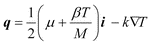
The nucleation process is illustrated in Fig. 3 for a system whose geometry is similar to that in Fig. 2. Here, L = 224, H = 64, W = B = 32, G = 80. The tops of the asperities slightly favor the A component, just enough to initiate nucleation, while the pockets in between the asperities selectively wet the B component. This particular geometry and wetting pattern can readily be fabricated through standard micro-contact printing methods.26 The initial value of the order parameter is chosen such that: (i) it lies inside the nucleation region, and (ii) there is enough of the minority (A) component to form bands that bridge the gap between the asperities. Bands of equal volume are then formed if, before quenching, the mixture is sufficiently uniform and if the asperities are placed equal distances apart.
 | ||
| Fig. 3 Formation of bands through nucleated growth from an initially homogeneous mixture (light blue). The tops of the asperities slightly favor one component (red), while the pockets selectively wet the other component (blue). | ||
Starting from the configuration shown in Fig. 3(d) and setting U = 0.02, we monitored the formation of droplets as this regular array of bands is subjected to an imposed shear (see Fig. 4). Due to the shear, the bands are stretched (Fig. 4(b)) and eventually break off when the contact between the bands and surfaces occurs only at points on the corners of the asperities (Fig. 4(c)). Earlier detachment would involve forming additional A/B interfaces near the surfaces and, thus, is energetically unfavorable. After a short transient state (Fig. 4(d–e)), each band transforms into a single droplet in the center of the gap in order to minimize its surface area (Fig. 4(f)).
 | ||
| Fig. 4 Formation of droplets from a regular array of bands under shear. The initial configuration is identical to that of Fig. 3(d). | ||
Although droplet formation in a shear cell is experimentally quite feasible, it might be preferable to have a fixed geometry and form droplets by applying a pressure gradient along the gap. We can tune the pressure gradient such that the bands snap off at the wall, without compromising the integrity of the band itself. Hence, under the correct conditions, as illustrated in Fig. 5, droplets can just as readily be obtained through an imposed pressure gradient as through an applied shear. The initial configuration was again identical to the final state in Fig. 3(d), while the imposed pressure gradient was 2 × 10⁻⁵.
 | ||
| Fig. 5 Formation of droplets from a regular array of bands under pressure driven flow. The initial configuration is identical to that of Fig. 3(d). | ||
In three dimensions, the appropriate confining walls would contain regularly spaced cylindrical asperities. The mechanism is then completely analogous to the two-dimensional case. The process is illustrated in Fig. 6. The tops of the asperities slightly favor the A component, just enough to initiate nucleation, while the sides of the asperities and the walls in between them selectively wet the B component. The initial value of the order parameter is again chosen such that it lies inside the nucleation region, and that there is enough of the A component to form columns that bridge the gap between the asperities. Here, L = 128 and U = 0.02. The gap between the asperities is H = 48, and the depth of the system in the vorticity direction is 56. The height and the radius of the asperities are B = 8 and R = 16, respectively; the separation between them in the flow-direction is G = 32. All fluid properties are the same as for the two-dimensional simulations.
 | ||
| Fig. 6 Formation of droplets under shear in three dimensions. | ||
Fig. 6(a–d) show the formation of the A columns; Fig. 6(e–h) show how we can utilize a shear flow to form a regular array of monodisperse droplets. Some caution must be taken in choosing the magnitude of the shear rate. While absent in two dimensions, the Rayleigh instability can cause planar sheets and cylindrical domains to break up into droplets in three dimensions. The same instability can cause the droplets that are formed to break up into smaller ones under the influence of a shear flow.27 This breakup process is controlled by the capillary number, Ca = ηγa/σ, characterizing the relative importance of shear stress and surface tension. Here, γ is the applied shear rate, σ is the surface tension and a is the radius of the A droplets. Hence, in experiments and in three-dimensional simulations, Ca must be <1 to ensure the formation of stable droplets.
The relevant dimensionless numbers that characterize the shear flow are the capillary number, as defined above, and the Reynolds number, Re = ργa2/η, based on the shear rate and droplet radius. For a typical binary fluid, σ = 0.01 N m−1, η = 0.05 Pa s, and ρ = 103 kg m−3. Hence, a = Re/400 for Ca = 0.1. For stability reasons, the maximum wall velocity in the LBM units is about 0.1, while the range of viscosities is from 0.01 to 10. Thus, for a typical simulation with a = 64, H = 128, Ca = 0.1, and the free energy parameters used above we can simulate a range of Reynolds numbers between 0.003 and 30. This corresponds to droplets with a radius between 7.5 μm and 75 mm. The corresponding values of W and G would also be of the same order.
Thermally patterned surfaces
There are a number of reasons for considering the effects that variations in temperature can have on the behavior of confined fluids. Temperature gradients are commonly exploited in the processing of polymeric materials and the growth of semiconductor crystals.28 Variations in temperature have also been harnessed to govern the flow of fluids in microfluidic devices.29 Thus, studies involving systematic temperature variations can provide guidelines for tailoring the processing conditions to yield the desired materials properties or system performance. In these latter applications, the modifications in temperature were intentionally introduced. On the other hand, variations in temperature are often difficult to regulate within reaction chambers and can lead to unintentional alterations of the material's properties. Studies on the effect of temperature variations can enhance our understanding of how uncontrolled temperature modulations affect the structure and properties of complex mixtures.As we noted in the Introduction, such thermal variations can have a particularly significant effect if they encompass a critical point, where the system changes phase behavior. We recently formulated a set of continuum equations and a corresponding LBM scheme6 to examine the system shown in Fig. 7, which shows a partially miscible AB mixture that is confined between two plates.30 The bottom plate is hot and is above the fluid's critical temperature, Tc, while the top plate is cold and lies below Tc. Near the bottom plate, the mixture forms a single, homogeneous phase. Since this region is relatively hot, the fluid becomes less dense and buoyancy drives it towards the top, colder plate, where the mixture phase-separates into distinct domains. Gravity will act on this relatively heavier mixture and force the fluid downward, whereupon the entire process repeats. Therefore, one can expect not only the creation of convective patterns (similar to Rayleigh–Benard convection), but also unique morphological patterns within the phase-separating fluid.
 | ||
| Fig. 7 Schematic of the system. | ||
To probe the behavior of the system, we performed simulations using a two-dimensional lattice where the height between the plates is H = 100 sites and a length of the plates is L = 180 sites. We applied periodic boundary conditions in the direction parallel to the plates, and no-slip, fixed temperature, neutrally wetting boundaries on the upper and lower plates. In each simulation, the initial state was given by ρ = 〈ρ〉 + (ΔT/H)(∂T p/∂ρp)y, 〈ϕ〉 = 0, and T = Tc − (ΔT/H)y, with a small amount of random noise added to each, to break the symmetry. Here, y = 0 denotes the center between the plates. The variation in density is such that the initial pressure is approximately constant. Unless otherwise stated, we use the parameters 〈ρ〉 = 1, g = 0.01, M = 0.2(ρ2 − ϕ2), k = 1, κ = 0.2, m = 1, and λ = 2; the critical temperature Tc= 2mρ0λ/kB = 4. The time-step Δt was taken to be 0.2, which is sufficiently small to prevent numerical instabilities. Simulations were performed for 2 × 10⁶ time-steps, which was large enough to observe the long-time behavior of the system.
In these studies, we explored the phase space as a function of the temperature difference between the top and bottom plates, ΔT, and the kinematic viscosity, ν. The phase diagram in Fig. 8 summarizes our findings. The symbols indicate points where simulations were performed, and the shaded regions are shown to clarify the approximate areas for each of the different regimes. As indicated by the diagram, a number of topologically distinct regimes were observed. We first consider the area marked “Regular stripes”, where the viscosity of the fluid is sufficiently high to suppress Rayleigh–Benard convection. An example of this case is illustrated in Fig. 9(a) for ν = 3 and ΔT = 0.5. The phase-separated fluid forms regular stripes of alternating A and B rich regions. Interestingly, the width-to-height ratio of the domains was found to be independent of simulation parameters. Because of the temperature gradient, there are local differences in the surface tension (σ) between the fluids, and consequently, we observe the Marangoni effect (the movement of fluid due to differences in σ) forcing fluid down the interfaces, and rising up the middle of each domain. We note that if we set the fluid velocity to zero, such that the system is governed only by the Cahn–Hilliard equation, we do not see this regular patterning. Instead, domains coarsen in time to reduce the global surface tension.
 | ||
| Fig. 8 Long time behavior of the fluid with viscosity ν and temperature difference ΔT. The periodic and chaotic areas refer to periodic and chaotic disturbances of the columns, respectively. Gravity driven Rayleigh–Benard convection is not observed in the regular stripes region. | ||
 | ||
| Fig. 9 Distribution of the order parameter ϕ, where gray corresponds to mixed fluid and white and black are A-rich and B-rich phases, respectively. The different regimes are ordered by increasing Rayleigh number Ra. (a) Regular stripes with no Rayleigh–Benard convection (Ra = 1719), (b) symmetric steady-state columns (Ra = 6875), (c) asymmetric steady-state columns (Ra = 6875), (d–g) periodic disturbance of the columns (the four frames show the evolution in simulation time-steps t, Ra = 14732), and (h) chaotic dripping (Ra = 5.1 × 10⁵). | ||
By decreasing the viscosity, we move into the “Steady-state columns” regime of the phase diagram. Fig. 9(b) illustrates a final steady-state structure for this region when ν = 1.5 and ΔT = 1. Fluid near the upper surface orders into alternating A and B horizontal bands. The phase-separated fluid is heavier than the mixture below it, and is forced downward by gravity, through columns. The flow field is similar to that observed in Rayleigh–Benard convection. The pattern in ϕ is advected with the fluid to produce the striped column structure. Fig. 9(c) shows another possible steady-state situation. In this case, the order of A and B downward from the upper surface is different on either side of the column, and asymmetric columns are produced. This picture was taken from part of a larger simulation containing six columns and using the same parameters as above. In large systems, both symmetric and asymmetric columns are observed. In the case of neutral wetting, the local ordering of phases near the surface results from the initial randomness. If the upper surface is preferentially wetted by one component, then only symmetric columns form.
For lower viscosities, the columns become unstable to a periodic disturbance. A set of snapshots for a typical example of the structure in the “Periodic” regime is given in Fig. 9(d–g) for ν = 0.7 and ΔT = 1. The four frames show the time evolution of the system through one period. It is probable that this instability results from a competition between gravity, pushing denser fluid down, and surface tension, which drives a reduction in total interface length. Periodic oscillations also occur in asymmetric columns. If the viscosity is reduced further, then the amplitude of the oscillation increases and the periodicity is lost (not shown).
Finally, when the viscosity is decreased even further, the system becomes unstable with respect to forming columns. For ν = 0.4, ΔT = 1, and k = 0.05, Fig. 9(h), illustrates a system that exhibits chaotic behavior and drips of phase-separated fluid are observed to come from the upper surface.
In the simulations, the Marangoni number, Ma = ρcvΔTH (dσ/dT)/kν, was typically of the order of 10 or less. This can be compared to, for example, the critical value Mac ≈ 80 for Marangoni convection at a free surface.31 The absence of a free surface in our problem (where there are only interfaces between A and B phases) makes the critical value even higher,31 implying that Marangoni convection does not drive the patterns we observe. Since the velocity profile is similar to that observed in Rayleigh–Benard convection, it is then natural to assume that the Rayleigh number, Ra = cvgH3Δρ/kν, can be used to characterize the system. Here, Δρ is the density difference between the top and bottom of the system in equilibrium. Fig. 8 shows the approximate Rayleigh number Rac ≈ 2270 for the transitions between convection and no convection. This is somewhat larger than that value of 1707, which is the analytical result for a single component fluid.32 In part, this results from the surface tension between the domains in Fig. 9(a), which inhibits convection.
The system parameters can be related to physical parameters in the following manner. A typical fluid has density ρ = 103 kg m−3, kinematic viscosity ν = 10−6 m2 s−1, and thermal diffusivity kd = 10−7 m2 s−1. By matching the Rayleigh number in the simulations to that in the physical system, we obtain a height H of the order of 1 mm.
It is worth noting that in phase field models, such as the lattice Boltzmann method, the interface width cannot be reduced to below 3 or 4 lattice units (around 30 μm) without the introduction of unphysical, non-isotropic disturbances of the velocity. However, in real systems, the interface width can be of the order of nanometers to hundreds of nanometers (depending on the depth of the quench). Therefore, since we observed that the stripe width is proportional to interface width,6 in an experiment, we would expect to observe a very large number of alternating layers of A and B fluids.33
An important observation that emerges from these studies is that an applied temperature gradient can be exploited to create patterned domains, as indicated by the image in Fig. 9(a). As an additional processing step, the entire system can be rapidly cooled below the melt temperature so that the confined fluid retains its patterned structure as it solidifies. The introduction of these striped domains can provide additional functionality to the resulting material.
Conclusions
We applied a mesoscale computational approach, the lattice Boltzmann method, to model the flow of binary fluids in chemically, physically or thermally heterogeneous chambers. Using this approach, one can readily introduce various fluid–fluid and fluid–surface interactions into the free energy for the system, and since the dynamic equations depend on the free energy (through the chemical potential and pressure), determine how these thermodynamic interactions affect the flow patterns and morphology. Furthermore, the interfaces in the system evolve naturally, without the need for ad hoc assumptions.As a first step to probing the role of heterogeneities on the flow patterns of the confined fluids, we examined the effects of chemically patterned substrates. Our studies yielded guidelines for optimizing the mixing of immiscible components in microfluidic devices. In the following studies, we integrated chemical and physical patterning to examine the flow of the AB immiscible fluids past surfaces that contain A-like asperities, which are regularly spaced on the top and bottom walls of the channels. The findings provided design criteria for creating emulsions with well-controlled morphologies. These studies highlight how the surfaces can be modified to yield the required performance at fluid/surface and fluid/fluid interfaces and consequently, the desired macroscopic properties. The studies also have the potential to reveal new phenomena that arises from the interplay between flowing complex fluids and chemically/physically patterned confining walls.
We also introduced a type of thermal patterning or heterogeneity by maintaining the top and bottom walls at different temperatures. By convecting a binary fluid through its critical transition temperature, we observed unique pattern formation. Since temperature gradients, surface tension and gravity play important roles during processing, the findings reveal phenomena that could be affecting the fabrication of a large class of materials. At the same time, the findings also reveal how these factors can be manipulated to create dynamically driven structures and thereby, create materials with unique morphologies, providing additional functionality to the final products.
Finally, we note that the processing of various materials involves the passage of a fluid phase through channels where chemical, structural or thermal heterogeneities at confining walls arise in an uncontrolled manner during the course of the processing and are difficult to regulate. These unintentional heterogeneities can have a tremendous effect on the morphology and properties of the final product. By performing simulations involving heterogeneous substrates, one can help pinpoint the extent to which local non-uniformities affect the structural evolution or phase ordering of the fluids and thus, the materials performance. These investigations can shed further light on the relationship between materials' processing and properties.
Acknowledgements
The authors thank Prof. Julia M. Yeomans for helpful discussions. We gratefully acknowledge financial support from the Office of Naval Research and the National Science Foundation.References
- O. Kuksenok, J. M. Yeomans and A. C. Balazs, Langmuir, 2001, 17, 7186 CrossRef CAS.
- O. Kusenok, J. M. Yeomans and A. C. Balazs, Phys. Rev. E, 2002, 65, 31502 CrossRef.
- R. Verberg, C. Pooley, J. M. Yeomans and A. C. Balazs, Phys. Rev. Lett., 2004, 93, 184501 CrossRef CAS.
- See for example: (a) Y. Xia, J. Tien, D. Qin and G. M. Whitesides, Langmuir, 1996, 12, 4033 CrossRef CAS; (b) D. B. Wolfe, J. B. Ashcom, J. C. Hwang, C. B. Schaffer, E. Mazur and G. M. Whitesides, Adv. Mater., 2003, 15, 62 CrossRef CAS; (c) Y. Xia and G. M. Whitesides, Angew. Chem., Int. Ed., 1998, 37, 550 CrossRef CAS.
- J. Leopoldes, A. Dupuis, D. G. Bucknall and J. M. Yeomans, Langmuir, 2003, 19, 9818 CrossRef CAS.
- C. Pooley, O. Kuksenok and A. C. Balazs, Phys. Rev. E, 2005, 71, 30501 CrossRef.
- (a) E. Orlandini, M. R. Swift and J. M. Yeomans, Europhys. Lett., 1995, 32, 463 CrossRef CAS; (b) M. R. Swift, E. Orlandini, W. R. Osborn and J. M. Yeomans, Phys. Rev. E, 1996, 54, 5041 CrossRef CAS; (c) A. Wagner and J. M. Yeomans, Phys. Rev. E, 1998, 59, 480.
- S. Chen and G. D. Doolen, Annu. Rev. Fluid Mech., 1998, 30, 329 Search PubMed.
- Y. H. Qian, D. d'Humieres and P. Lallemand, Europhys. Lett., 1992, 17, 479 CrossRef.
- S. Succi, The Lattice Boltzmann Equation For Fluid Dynamics and Beyond, Oxford University Press, Oxford, 2001 Search PubMed.
- A. J. Bray, Adv. Phys., 1994, 43, 357.
- J. W. Cahn, J. Chem. Phys., 1976, 66, 3667.
- V. M. Kendon, M. E. Cates, I. Pagonabarraga, J.-C. Desplat and P. Bladon, J. Fluid Mech., 2001, 440, 147 Search PubMed.
- A. J. C. Ladd, J. Fluid Mech., 1994, 271, 285 CAS.
- O. Kuksenok and A. C. Balazs, Phys. Rev. E, 2003, 68, 11502 CrossRef.
- O. Kuksenok and A. C. Balazs, Physica D, 2004, 198, 319 CrossRef.
- O. Kuksenok, D. Jasnow and A. C. Balazs, Phys. Rev. E, 2003, 68, 51505 CrossRef.
- O. Kuksenok, D. Jasnow, J. M. Yeomans and A. C. Balazs, Phys. Rev. Lett., 2003, 91, 108303 CrossRef.
- L. D. Landau and E. M. Lifshitz, Fluid Mechanics, 2nd edn., Pergamon Press, London, 1959 Search PubMed.
- B. J. Palmer and D. R. Rector, Phys. Rev. E, 2000, 61, 5295 CrossRef CAS.
- J. L. Wilbur, A. Kumar, H. A. Biebuyck, E. Kim and G. M. Whitesides, Nanotechnology, 1996, 7, 452 CrossRef CAS.
- B. Zhao, J. Moore and D. J. Beebe, Science, 2001, 291, 1023 CrossRef CAS and references therein.
- Y. Oono and S. Puri, Phys. Rev. A, 1988, 38, 434 CrossRef CAS.
- D. Gottlieb and S. Orszag, Numerical Analysis of Spectral Methods: Theory and Applications, Arrowsmith, Bristol, 1977 Search PubMed.
- Here, “nucleated growth” means that wall interactions drive the fluid into the spinodal region.
- A. Kumar, H. A. Biebuyck and G. M. Whitesides, Langmuir, 1994, 10, 1498 CrossRef CAS.
- A. J. Wagner, L. M. Wilson and M. E. Cates, Phys. Rev. E, 2003, 68, 45301 CrossRef CAS and references therein.
- J. Kumaki, T. Hashimoto and S. Granick, Phys. Rev. Lett., 1996, 77, 1990 CrossRef CAS and references therein.
- D. E. Kataoka and S. M. Troian, Nature, 1999, 402, 794 CrossRef CAS.
- Ultimately, we will use this approach to examine a variety of thermal gradients, or “patterns”, along each surface; here, however, we start by considering the simplest scenario where a thermal gradient is introduced by having the top and bottom surfaces being set at different, uniform temperatures.
- A. Nepomnyashchy, M. Velarde and P. Colinet, Interfacial Phenomena and Convection, Chapman and Hall/CRC, London, 2002 Search PubMed.
- S. Chandrasekhar, Hydrodynamic and Hydromagnetic Stability, Clarendon Press, Oxford, 1961 Search PubMed.
- However, it is possible that there exists some stripe coarsening process at very high stripe number, which would reduce the large interfacial energy. In addition, Brownian noise, which was not included in these simulations, may be important for stripe stability.
| This journal is © The Royal Society of Chemistry 2005 |