Pattern formation by temperature-gradient driven film instabilities in laterally confined geometries
Mihaela
Nedelcu
a,
Mihai D.
Morariu
b,
Stephan
Harkema
b,
Nicoleta E.
Voicu
ab and
Ullrich
Steiner
*a
aDepartment of Physics, University of Cambridge, Cambridge, UK CB3 0HE Web: www.phy.cam.ac.uk/steiner
bDepartment of Polymer Chemistry and Materials Science Center, University of Groningen, Nijenborgh 4, NL-9747, AG Groningen, The Netherlands
First published on 29th March 2005
Abstract
Film break-up driven by an electric field or temperature gradient typically exhibit a characteristic length scale. The presence of a lateral confinement significantly alters this pattern formation process.
Soft lithography has in recent years matured to a technology that rivals more established lithographic techniques.1 The array of soft-lithographic methods has continuously increased over the past 10 years to include a variety of printing, moulding, embossing,2 demixing,3 and dewetting4,5 approaches. Very recently, it was shown that capillary instabilities triggered by electric fields6 and temperature gradients7,8 can also be harnessed for lithography.9,10 The main issues that prevent the replacement of established lithographic techniques (i.e. photolithography) by soft lithography are the lack in reproducibility and large area replication, however. In addition, the formation of sub-structures often leads to a lack of pattern replication or the appearance of undesired superposed patterns. This is well known in the case of molding and embossing techniques, where air that is trapped between mold and resist can lead to unreliable pattern replication.11 Spurious patterns that deteriorate the outcome of the lithographic process arise from viscous fingering and capillary instabilities caused by electrostatic charging, applied electric fields, or temperature gradients.
As with most pattern formation processes, instabilities that lead to undesired effects in a lithographic method can be turned into an advantageous part of the process itself. The necessary control of the structure formation process requires, however, the detailed understanding of the pattern generating mechanism. This was demonstrated, for example, for capillary surface instabilities, which were controlled with the help of electric fields,9 temperature gradients,10 or by capillary bridging.12
In this communication, we report a pattern formation process that takes place in a one-dimensional confinement in the presence of a temperature gradient. The structure formation arises from a capillary instability that occurs when thin polymer films are exposed to a temperature gradient.7 The mechanism of this pattern formation process depends on the details of the heat transport across the polymer film and the enclosed air gap, as described before.8 In thin, viscous polymer layers, heat is conducted by the diffusion of thermal excitations (phonons). The low-frequency part of the phonon spectrum exerts a radiation pressure that is strong enough to destabilize the polymer–air interface. This leads to a redistribution of the polymer towards a conformation that spans the hot and cold plates. Combined with a topographically patterned plate, this mechanism can be employed in a lithographic technique.10 Here, we describe how the pattern formation is modified when the film is laterally confined to a quasi-one-dimensional geometry, which is generated by a line grating that is brought into contact with a liquid polymer film.
The experimental set-up is illustrated in Fig. 1. A ca. 100 nm thick polymer film was spin cast onto a silicon wafer. In this study polystyrene (PS, molecular weight: 94.4 kg mol−1, polydispersity: 1.06) was used, but we expect this effect to be independent of the materials of the substrate or the film. Facing the polymer film, a patterned silicon template was placed. The template surface was covered by a octadecyltrichlorosilane self-assembled monolayer (SAM) to facilitate the template release. The assembly was heated to T = 165 ± 1 °C, above the glass transition temperature of the polymer. By applying gentle pressure, the surface of the protruding template structures was brought into contact with the liquid polymer film. This resulted either in the embossing of part of the template topography into the polymer film or in a very small separation of the template and the polymer film (Fig. 1a).
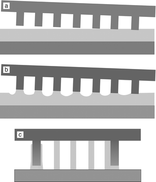 | ||
| Fig. 1 Schematic representation of the experimental set-up. (a) A patterned template is brought into contact with a liquid polymer film, causing the partial embossing of the template into the film. (b) In the presence of a vertical temperature gradient, the polymer is drawn toward the template protrusions, thereby partially replicating the template. (c) Magnified view: for long times the remaining polymer film becomes unstable, forming columns (middle) or wall-adsorbed columns (right). In the presence of a vertical temperature gradient, thermocapillary flow covers the template protrusions with a thin polymer layer (left). | ||
Two situations are distinguished. If the template had the same temperature as the polymer sample (by heating the assembly in a vacuum oven), the situation schematically shown in Fig. 1a remained stable for more than 66 h. The polymer film morphology changes, however, if the temperature of the top-template was reduced to T = 141 ± 1 °C by convectional cooling. The resulting vertical temperature gradient causes a partial replication of the template in the regions where the template was not pressed in10 (Fig. 1b). For longer times, a surface undulation destabilized the polymer surface both in the parts of the sample that were not laterally confined, as well as in the template grooves (Fig. 1c). After an annealing time of 68 h, the polymer was solidified by cooling the set-up to room temperature and the template was removed. The sample was then imaged by optical and atomic force microscopy (AFM). Due to the reduced polymer adhesion (by SAM coverage) of the template, all polymer remained on the substrate, as verified by imaging of the template.
The results in Fig. 2 show three distinct morphologies as a function of the confinement c, defined by the ratio of the groove width w and the intrinsic unconfined column diameter d0 = 4.1 ± 0.7 µm (Fig. 3c): c = w/d0.
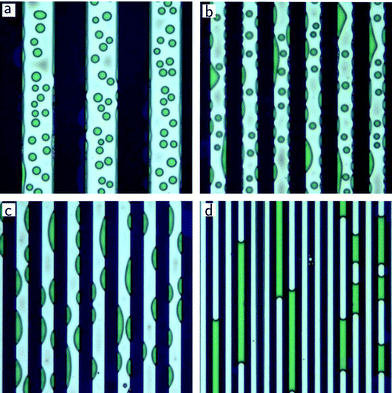 | ||
| Fig. 2 Temperature-gradient driven capillary instability in confined geometries. Topographic line-grid templates that were brought in contact with a liquid polymer film give rise to a quasi-one-dimensional confinement of width w of the free polymer surface. (a) w = 12 µm: similar columnar pattern as in the unconfined case (Fig. 3c). (b) w = 6 µm: coexistence of free columns with circular cross-sections and wall-adsorbed columns with drop-shaped cross-sections. (c) w = 4.5 µm: drop-shaped columns only. (d) w = 2 µm: plugs spanning the confining walls. The size of optical microscopy images are 70 × 70 µm2. The height of the polymer columns and plugs is determined by the distance of the line grooves to the substrate (580–630 nm). | ||
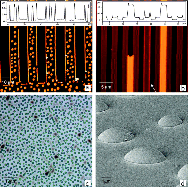 | ||
| Fig. 3 (a), (b): AFM images corresponding to Fig. 2a and d. The insets are height profiles horizontally across the lower part of the images. Both images show the formation of thin, homogeneous polymer layers on the confining walls. These layers may have formed by thermocapillary spreading (see Fig. 1c (left)). The optical micrograph in (c) shows the column formation driven by a vertical temperature gradient in an area of the sample that was not laterally confined. The SEM image in (d) shows PS drops with a contact angle of ca. 50° on a SAM covered silicon wafer. | ||
For c = 2.9 ± 0.5 in Fig. 2a, the structure formation process was influenced only little by the confinement. The columnar morphology in the grooves qualitatively mirrors the pattern formation of the laterally unconfined case (Fig. 3c). The redistribution of the polymer from a layered to a vertical conformation is, however, influenced by the template grating in the regions near the confining walls. For lateral distances from the walls smaller than the column diameter, column formation was suppressed. Instead, a homogeneous layer (particularly well visible in the AFM image in Fig. 3a) has formed on the confining walls.
For smaller values of c, the confinement has a profound influence on the pattern formation process. For c = 1.5 ± 0.2, a coexistence of columns with wall-adsorbed polymer morphologies with drop-shaped cross-sections was observed (Fig. 2b). The mean size of the free columns has decreased. Columns with diameters comparable to the line width have made contact with the walls, giving rise to morphologies with cross-sections that resemble the partial wetting of a liquid on a flat substrate (Fig. 3d). A further decrease of c resulted in the increased incorporation of the free columns into the material that is adsorbed to the side walls. For c = 1.1 ± 0.2 in Fig. 2c, all vertical polymer structures made contact with the confining walls and no remaining free columns were observed.
A more detailed analysis reveals the effect of the lateral confinement on the column distribution. Compared to the average column diameter d0 = 4.1 ± 0.7 µm measured in the non-structured regions of the sample (Fig. 3c), the average column size is reduced to d = 3.2 ± 0.5 µm for c = 2.9 ± 0.5 (Fig. 2a) and d = 2.1 ± 0.4 µm for c = 1.5 ± 0.2 (Fig. 2b). With increasing confinement, the largest columns are increasingly likely to make contact with the confining walls and become part of the wall morphology. This causes a decrease in the average column diameter and a more narrow diameter distribution. Apart from the transition from free to adsorbed columns with increasing confinement (decreasing value of c), there is also a transition in the morphology of the polymer in contact with the side walls, from homogeneous layers in Fig. 2a to cylinders with drop-shaped cross-sections in Fig. 2b,c.
It is instructive to compare the polymer morphologies in contact with the side walls in Fig. 2a–c to dewetting experiments. To this end, a ca. 100 nm thick PS film was spin-cast onto a silicon substrate that was covered by a self-assembled monolayer to create a planar surface that was chemically similar to the confining walls. After annealing for ca. 33 h at 170 °C, the film has broken up and drops with spherical cross-sections have formed. The PS-drop contact angle of 45–50° (45° determined by AFM, 50° determined by scanning electron microscopy (SEM, Fig. 3d)) was comparable to the cross-sectional contact angle of the wall-adsorbed polymer of ca. 46° in Fig. 2b and ca. 49° in Fig. 2c. Since the applied temperature gradient gives rise to polymer morphologies that span the hot and cold boundaries, the wall adsorbed structures are cylinder cuts with a cross-sectional contact angle that is given by the equilibrium contact angle.
A second change in morphology occurs upon a further increase in confinement to c < 1. Fig. 2d shows the formation of lateral capillary plugs for c = 0.49 ± 0.07. Qualitatively, these plugs are expected to appear for small enough groove widths that cause the polymer structures from Fig. 2c to overlap. Rather than forming capillary bridges with volumes corresponding to free columns, much larger elongated plugs were observed. This is not only a consequence of a lateral coalescence process within each groove, but material is also drawn in from the film under the adjacent grooves. The formation of plugs in adjacent grooves is therefore not observed and typically, plugs are found only in every second groove. As opposed to the structures observed for c > 1 (Fig. 2a–c), where the pattern formation in each confined line seems independent of the adjacent regions, there is a clear cross-talk in the pattern formation process for c < 1. This is due to the fact that plugs in adjacent grooves are interconnected via the polymer that is in contact with the downward protruding parts of the template. In the limit of such a strong confinement, capillary forces are a dominant factor in the structure formation process.
The careful examination of Fig. 2d reveals a second structure forming process. In some cases (arrow in Fig. 3b) a thin homogeneous layer is formed on the confining walls. These thin wetting layers are stable only if the two adjacent grooves are free of plugs over their entire length. Once a plug is formed, the thin wall layer is drained into the plug, thereby reducing the vertical surface area of the polymer.
Finally, we turn our attention to the two types of morphologies of the polymer that are in contact with the wall. While the polymer structures with drop-shaped cross-sections arise from the fact that PS forms a contact angle of 45–50° with a SAM covered silicon wafer (Fig. 3d), the homogeneous layers that have formed in Fig. 2a and d are somewhat surprising. We propose that the applied temperature gradient plays a role in the formation of these vertical layers. Despite the better heat conductivity of the silicon template compared to the polymer, the applied temperature difference leads to a vertical temperature variation along the confining walls. A liquid in contact with a substrate exhibiting a temperature gradient experiences a surface shear stress caused by the temperature dependent surface tension.13 This gives rise to a thermocapillary flow of the liquid in the direction of the lowest temperature. This mechanism provides an effective process to produce homogeneous coatings.14 In our experiments, the protruding parts of the template are in contact with the polymer. A temperature gradient along the template in the vertical direction will therefore give rise to thermocapillary spreading of the polymer to coat the side walls in a homogeneous fashion, schematically shown in Fig. 1c (left). Since this process competes with the other structure formation processes described above, these thin thermocapillary layers are stable only if they are not connected to the other morphologies that form at the confining walls (plugs or drop-shaped columns).
In summary, we have investigated pattern formation processes in a polymer films caused by a temperature gradient normal to the polymer surface. When confined into a line geometry, two competing pattern forming mechanisms were identified: (1) the amplification of capillary instabilities, leading to columns that span the hot and cold boundaries and (2) thermocapillary flow that leads to a homogeneous coating of the confining walls. With increasing lateral confinement, a transition from circular columns to wall adsorbed columns with a drop-shaped cross-section was observed. The relevant lateral length scale is the unconfined column diameter, which is controlled by the magnitude of the applied temperature gradient.8 For a confinement smaller than this characteristic length scale, the columns coalesce to large plugs that span the confining walls. We emphasise that the effect described here differs from soft-lithography approaches in which polymer liquid is drawn into the grooves of the template by capillary forces.15 While this may play a role for the strongest confinement (Fig. 2d), it is generally suppressed due to the reduced surface energy of the template.
The detailed pattern formation mechanisms described here are of possible practical relevance. During hot embossing, if not all the air is expelled when the template is pressed into the liquid polymer, the presence of temperature gradients may lead to undesired additional patterns.11 In a more positive context, it may be possible to fine-tune the temperature-gradient driven pattern formation for a lithographic application. To this end, it would be useful to enhance the thermocapillary effect on the expense of the column-forming instability, for example by using a template material with a lower heat conductivity. This way, patterns with small lateral dimensions and high aspect ratios can be replicated, in analogy to similar processes that are driven by electric fields.
This work was partially supported by the Dutch “Stichting voor Fundamenteel Onderzoek der Materie” (FOM) and the Dutch Polymer Institute (DPI).
Notes and references
- Y. Xia, J. A. Rogers, K. E. Paul and G. M. Whitesides, Chem. Rev., 1999, 99, 1823 CrossRef CAS.
- S. Y. Chou, P. R. Krauss and P. J. Renstrom, Science, 1996, 272, 85 CrossRef CAS.
- M. Böltau, S. Walheim, J. Mlynek, G. Krausch and U. Steiner, Nature, 1998, 391, 877 CrossRef CAS.
- H. Gau, S. Herminghaus, P. Lenz and R. Lipowsky, Science, 1999, 283, 46 CrossRef CAS.
- R. Seemann, M. Brinkmann, E. J. Kramer, F. F. Lange and R. Lipowsky, Proc. Natl. Acad. Sci. USA, 2005, 102, 1848 CrossRef CAS.
- E. Schäffer, T. Thurn-Albrecht, T. P. Russell and U. Steiner, Europhys. Lett., 2001, 53, 518 CrossRef CAS.
- E. Schäffer, S. Harkema, R. Blossey and U. Steiner, Europhys. Lett., 2002, 60, 255 CrossRef CAS.
- E. Schäffer, S. Harkema, M. Roerdink, R. Blossey and U. Steiner, Macromolecules, 2003, 36, 1655.
- E. Schäffer, T. Thurn-Albrecht, T. P. Russell and U. Steiner, Nature, 2000, 403, 874 CrossRef CAS.
- E. Schäffer, S. Harkema, M. Roerdink, R. Blossey and U. Steiner, Adv. Mater., 2003, 15, 514 CrossRef CAS.
- H. Schift, L. J. Heyderman, M. Auf der Maur and J. Gobrecht, Nanotechnology, 2001, 12, 173 CrossRef CAS.
- S. Harkema, E. Schäffer, M. D. Morariu and U. Steiner, Langmuir, 2003, 19, 9714 CrossRef CAS.
- E. M. Lifshitz and L. D. Landau, Fluid Mechanics; Pergamon Press, London, 1959 Search PubMed.
- V. Ludviksson and E. N. Lightfoot, AIChE J., 1971, 17, 1166 CrossRef CAS.
- K. Y. Suh and H. H. Lee, Adv. Mater., 2002, 14, 349.
| This journal is © The Royal Society of Chemistry 2005 |