Three- and four-way parallel factor (PARAFAC) analysis of photochemically induced excitation–emission kinetic fluorescence spectra
Michelle L.
Nahorniak
,
Gary A.
Cooper
,
Yoon-Chang
Kim
and
Karl S.
Booksh
*
Department of Chemistry and Biochemistry, Arizona State University, Tempe, AZ, USA. E-mail: booksh@asu.edu; Fax: (480) 965-2747; Tel: (480) 965-3058
First published on 8th November 2004
Abstract
Independently emerging fluorescence profiles of unknown, photochemically induced degradation products of several naturally non-fluorescent pesticides were monitored using single exposure excitation–emission fluorescence spectroscopy. Three-way parallel factor analysis (PARAFAC) was employed to uniquely resolve the pure fluorescent spectra of the overlapping photolysis products. The quantitative utility of EEM photolysis-based determinations was demonstrated by employing four-way PARAFAC models built from EEM time cubes of multiple fenvalerate samples. The 4-way PARAFAC models were then used to predict original pesticide concentrations resulting in conservative limit of detection and root mean square errors of calibration (RMSEC) of 3 µM each.
1. Introduction
Pesticides and herbicides are an essential part of modern agricultural practice, but these can accumulate in and pollute ground and surface waters. Pesticide determinations typically involve multi-step, time-consuming, procedures that limit the ability to perform real time and on-site analyses. For example, in extraction and/or pre-concentration followed by gas chromatography (GC) or high-performance liquid chromatography (HPLC), separation is commonly performed prior to analysis. Because of the demand for quick, inexpensive and reliable organic pollutant determination methods, there is much interest in exploring alternative analytical methods. Although GC with mass spectrometric (MS) detection and HPLC with UV-Vis detection are two of the main techniques used for pesticide residue analysis, fluorometric detection tends to be more sensitive.1 Improvement in the selectivity of fluorescence spectroscopy has been derived from the application of the parallel factor (PARAFAC) model into the collection of a two-dimensional total fluorescence spectrum, termed an excitation–emission matrix (EEM).2–7 This multi-way spectral deconvolution method allows for accurate and reliable discrimination of the analyte signal in the presence of unknown and uncalibrated spectral interferents.3Much interest has been recently directed at employing EEM fluorescence spectroscopy with PARAFAC modeling to quantitative and qualitative analyses of complex mixtures. Target applications include pesticides,3,8 pharmaceuticals9,10 and natural products.6,11 These applications rely on the ability of three-way PARAFAC to exploit the partial selectivity in the excitation, emission and concentration dimensions of the data set. When selectivity in one of the three dimensions is absent, the resolution power of PARAFAC is limited. However, chemical reactions involving the generation or degradation of a fluorophore may provide a fourth dimension of analysis with selectivity appropriate for resolution by four-way PARAFAC. This strategy was employed by Nikolajsen et. al. for the analysis of two non-fluorescent stress hormones in urine,11 and by Olivieri et. al. for the analysis of non-fluorescent leukemia drugs in urine12 (and is investigated here for the analysis of four non-natively fluorescent pesticides).
While the use of fluorescence for trace analysis has traditionally been limited to direct analysis of strongly fluorescent species,1 many non- or weakly fluorescent highly aromatic pesticides can be chemically or non-chemically converted into fluorescent species. For example, fluorogenic labeling, chemical derivatization, and complexation reactions are commonly employed in fluorometric pesticide analysis. An alternative approach is the use of photons instead of chemical reagents to induce fluorescence in a process termed photochemically induced fluorescence (PIF). Exposure to ultraviolet radiation has been shown to initiate fluorescence in several normally non-fluorescent pesticides.13–15 These simple photolysis reactions are relatively fast, and inexpensive, and can circumvent analyte dilution. These merits make PIF a good candidate for field analysis and screening. Real-time monitoring of PIF adds an order of selectivity to fluorescence spectroscopy. Because photolysis times are characteristic of a compound, simultaneous determinations in mixtures may be possible by optimizing UV exposure times. Because fluorescence peaks tend to be broad and featureless, traditional spectroscopic techniques are often unable to resolve analyte spectra from interferent spectra or background fluorescence. Employing photolysis techniques prior to analysis can further complicate the situation because the fluorescence signal is often the sum of overlapping spectral profiles of multiple degradation products.
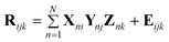
In standard multivariate analysis, data is arranged as a matrix. For example, the fluorescence emission spectra of a set of calibration standards can be arranged as the rows of a matrix. In this case, the rows correspond to the sample and the columns correspond to the emission wavelengths. This data lends itself naturally to two-way multivariate analysis methods such as Principal Component Recognition (PCR) and Partial Least Squares (PLS).16 However, some data types naturally lend themselves to a higher order structure. For example, three-way data can be generated by combining multiple two-way data obtained from hyphenated instrumentation such as GC-MS, 2D-NMR and EEM. In each of these cases a matrix of data is generated for a single sample. A series of data matrices obtained from multiple samples can be combined to form a data cube. Fig. 1 shows the stacking of multiple EEMs to form the three-way data cube, R. In the EEM spectroscopy, a total fluorescence spectrum is obtained by systematically varying the excitation and emission wavelengths and collecting the resulting J by K data matrix. Each of the J rows in the EEM spectrum is the emission spectrum at the jth excitation wavelength. Each of the K columns in the EEM spectrum is the excitation spectrum at the kth emission wavelength. One of the most valuable features of all multi-way data, including EEM spectra, is that it permits the use of powerful multi-way spectral deconvolution methods that enable calibration of multiple analytes in the presence of unknown, uncalibrated interferents.17,18 This can minimize or eliminate traditionally time-consuming sample pretreatments and facilitate probing of an analyte in its native environment. One common multiway chemometric deconvolution method is PARAFAC analysis.17 The PARAFAC algorithm decomposes the data cube R into three matrices, X, Y and Z, by generating a trilinear model that minimizes the sum of the squares of the residuals. Each matrix represents one dimension of the cube containing N factors. (N is the smallest number of factors that can describe the variance in the data, where no factor can be described by a linear combination of the others.) The cube R can be mathematically modeled by a set of trilinear components according to the following equation:
 | (1) |
 | ||
| Fig. 1 Stacking multiple EEMs forms the three-way data cube R. | ||
In the case of a series of EEM spectra, Rijk is the fluorescence intensity of sample k at the excitation wavelength i and the emission wavelength j, N is the user specified number of unique spectral profiles in the data cube, the n columns of X are the predicted pure excitation spectra of the analytes, the n columns of Y are the predicted pure emission spectra of the N factors, and the columns of Z are the n predicted pure spectral intensity (e.g. concentration) profiles of the N factors, and Eijk is the error matrix. By exploiting the inter-relationship between the inherent excitation (X) and emission (Y) profiles throughout the multiple samples, the resolved spectra are obtained and the resolved relative concentrations (Z) of the N factors among the samples can be employed for calibration. Mathematical proofs show that this decomposition of R is unique in X, Y and Z except for a scaling factor.19 In the experiments described in this text, a weighted version of PARAFAC was used to give the weight of areas of the EEM displaying Rayleigh scattering a weight of zero and all other areas of the EEM a weight of one, avoiding the need to ignore spectral information near the Rayleigh signal.2
Although in theory there is no limit to the number of “ways” possible, data higher than three-way is not typically used for routine analysis or practical applications. Three- and four-way PARAFAC analyses are applied here to the PIF determination of four non-fluorescent pesticides The fluorescent profiles of the photolysis product(s) of interest can be resolved from fluorescent constituents in the sample matrix as well as from other fluorescent products that may form. The data only needs to be treated as trilinear even if if a four-way model is applied; the samples are quadrilinear with respect to concentration provided a psuedo-first order kinetic model is inferred as evidenced by the calibration model. Yet, non-linear models may still be utilized if the necessity arises. The time dependent formation of fluorescent products provides an additional order of selectivity with which to resolve the analyte of interest. In this manner, EEM-time cubes of data can be collected for each sample. The PIF profiles are specific to the pesticide under investigation and correspond linearly to the degradation products, and thus the concentration of the original pesticide. It is proposed that these temporally resolved profiles could be used to identify and quantify aqueous pesticides in the field with minimal sample preparation.
In this study, the photochemical and spectrofluorometric analyses of the naturally non-fluorescent pesticides fenvalerate, deltamethrin, diflubenzuron, and lufenuron are described. Fenvalerate20 is a synthetic pyrethriod insecticide used to control a wide variety of insects on food crops, fruits, and vegetables. Deltamethrin21 is used to control a variety of pests on stored cereals post harvest and on fruits and vegetables in fields and green houses. Diflubenzuron,22,23 a benzamide insecticide, is applied to forests and field crops to selectively control insects and parasites. Lufenuron is a chitin inhibitor commonly fed to pets to control fleas. Lufenuron is the active ingredient in commercial products Program (Novartis Animal Health US, Inc., Greensboro, NC, USA), Advantage (Bayer AG, Leverkusen, Germany) and Frontline (Merial Animal Health Ltd., Harlow, Essex, UK ).
2. Experimental
2.1. Instrumental
Although an EEM is typically produced by scanning the excitation spectrum at multiple emission wavelengths (or vice versa) and combining the spectra, the data collection time for such a practice is impractical for in-situ analysis or analysis of evolving processes. For example, since each scan is taken at a different time, in a dynamic environment the individual spectra may not truly represent the same sample. Single measurement EEM fluorescence was first introduced in 1977 by Christian et al.24,25 and the relatively recent development of the imaging spectrographs has renewed interest in the technique.26,27The EEM fluorometer used in the following text is modeled after that of Muroski27 and has been described previously.3,4,28 A 75 W xenon lamp is focused onto an 1/8th meter imaging spectrograph (Acton Research Group, Acton, MA) with the exit slit rotated 180 degrees. This produces an incident spectrum such that the excitation photons are spatially dispersed vertically across the cuvette in a sample chamber, which is equipped to hold either a standard cuvette or a flow cell. Light emitted 90 degrees from incident is focused onto the slit of the entrance slit of a second imaging spectrograph. The two spectrographs were equipped with 300 groove mm−1 gratings blazed at 300 nm and 500 nm, respectively. The emission spectra are focused onto a low resolution imaging SBIG ST-6 CCD (Santa Barbara Instrument Group, Santa Barbara, CA). The 240 × 750 pixel chip in the ST-6 camera was binned in 2 × 3 pixel blocks to yield a 120 × 250 pixel EEM spectrum for each sample. An entire EEM spectrum is collected in a single measurement in less than 1 min. The EEM spectrometer has been adapted to run off dc power and thus can be field-portable. The 75 W Xe lamp requires 14 V and draws 5 A h−1, and can be powered in the field for 15 h using two 12 V, 75 A h−1 deep cycle batteries.28
2.2. Materials
Analytical grade PESTANAL standards of fenvalerate, lufenuron, and deltamethrin, manufactured by Riedel de Haen, were purchased from Sigma–Aldrich. Diflubenzuron was obtained as a 90% concentrate from Uniroyal Chemical Company in Midddlebury, CT. The pesticides were used without further purification and dissolved and diluted in absolute ethanol (Aaper Alcohol and Chemical Company, Shelbyville, KY), low grade acetone, anhydrous methanol (Malinckroft AR) or reagent grade isopropanol.2.3. Procedures
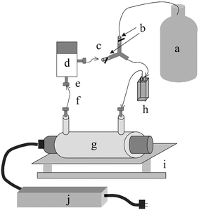 | ||
| Fig. 2 Flow cell based photolysis system: a, analyte solution; b, on/off valves; c, “Open” or “Closed” loop; d, pump; e, 1/4″ 28 PEEK nuts; f, 1/8″ OD Teflon FEP tubing; g, lamp and sheath; h, flow cell; i, shaker; j, ballast. | ||
3. Results and discussion
3.1. Fenvalerate
Three way PARAFAC models were calculated for each of the three fenvalerate samples (120 × 250 × 50 data cubes). The three factor model (Fig. 3) was found to most accurately represent the photolysis of fenvalerate. By examining the raw EEM images as they evolve over time, it appears that three unique fluorescent profiles indeed emerge. Predicted EEMs of each factor in the three factor model were reconstructed from the predicted excitation, emission and concentration profiles. In Fig. 4A–C the three predicted EEMs are overlaid on representative actual EEMs acquired after 9, 70, and 300 min of ultraviolet exposure. The similarity between the actual and predicted EEMs provides further evidence of the validity of the three factor model. Upon examination of the predicted concentration profiles from the three factor model, it can be seen that the first product (labeled “A” in Fig. 3c) forms rapidly then slowly decays. A second product (labeled “B”) begins to appear after the first 20 min of UV exposure. A third product (labeled “C”) initially forms slower than the first product labeled “A”, but in the end achieves a much greater fluorescent intensity than either of the other two products. This product is likely a secondary photolysis product of “A”. Although the photolysis reaction was followed for 300 min, normalizing the change in spectral intensity over time for each factor in the three-factor model revealed that most of the degradation occurs within the first hour of UV exposure. | ||
| Fig. 3 Predicted excitation, emission, and time dependant intensity profiles of 10 × 10−5 M fenvalerate photolysis employing (a) one, (b) two, (c) three and (d) four factor 3-way PARAFAC models. | ||
 | ||
| Fig. 4 Predicted fenvalerate EEMs (isobars) overlaid on actual EEMs (images) acquired after (a) 9, (b)70, and (c) 300 minutes of UV exposure. | ||
One, two, and four factor models were constructed for the collected spectra and dismissed for not accurately describing the observed chemical degradation. Both the one and two factor models were too simplistic. The three spectral profiles from each model appeared viable; however, the Frobenius norm of the residuals from fitting the model to the data were very large. Including an additional factor significantly decreased the magnitude of the residuals. Concurrently, increasing the model complexity from three to four factors did not significantly improve the fit of the data, and all three resolved profiles were chemically logical. For the four factor model, three of the resolved spectral profiles have similar shapes to the profiles in the three factor model, except the fourth emission profile, which becomes partially negative while adopting a ‘first derivative’ shape, indicating that the fourth factor is not needed to describe the chemical change observed during photolysis. The observation of this negative behavior generates no qualitative difference and still allows for the most simple mode of analysis.
3.2. Diflubenzuron
The time evolved PIF spectrum of diflubenzuron is shown in Fig. 5 for both methanol and isopropanol solvents. Visually, it appeared that that a single peak formed during the photolysis of diflubenzuron and the intensity increased over time. One, two, three and four factor PARAFAC model results confirmed this observation. The models with more than one factor resulted in factors with very uncharacteristic excitation and emission profiles, and multiple factors with similar time profiles. The means of the Frobenius norms of the residual spectra were on the order of 2 × 10⁴ for the one, two, three and four factor PARAFAC models. The fact that the residuals do not decrease as the number of factors in the PARAFAC model increases supports the choice of a one factor model. The PARAFAC results were qualitiatively equivalent for both solvents. | ||
| Fig. 5 Predicted 1 factor model diflubenzuron EEM overlaid on actual EEM acquired after 36 min UV exposure. | ||
3.3. Lufenuron
PARAFAC analysis of the Lufenuron spectra fail to conclusively return a believable model of the analyte photodegradation. One, two, three, four and five factor weighted PARAFAC models were built from the data and the results of the (a) one, (b) two, and (c) three factor models are shown in Fig. 6. The predicted emission profile resulting from the one factor model does not appear smooth enough to represent a pure fluorescence spectrum. The two factor model results in one of the predicted emission spectra having a negative portion. The most logical results are obtained by using a three factor model and ignoring one of the factors. However, when EEMs reconstructed from the two factors are overlaid on an actual EEM taken during the photolysis process (Fig. 7) the two factors do not seem to completely describe the actual EEM. An actual peak between the predicted peaks A and B exists. The multiple peaks of the time profile of factor B in Fig. 6 could indicate that this factor is actually a combination of two separate fluorescent peaks representing an intermediate and a final photolysis product. If this is the case, factor B should theoretically be modeled by two separate factors. However, more complex PARAFAC models failed to adequately model the system.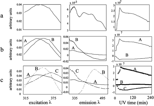 | ||
| Fig. 6 Lufenuron photolysis: (a) one, (b) two and (c) three factor PARAFAC model results. | ||
 | ||
| Fig. 7 Predicted EEMs of two of the factors resulting from the three factor model overlaid (isobars) on an actual EEM (image) acquired during lufenuron photolysis. | ||
Calculation of the Frobenius norm of the residual EEM spectra over time for the various models further supports the choice of a three factor model. The one and two factor models result in Frobenius norms of the residual EEM spectra with a mean of 3.6 × 10⁴ and 1.3 × 10⁴ (arbitrary units), respectively, while the Frobenius norms of the three factor model residual spectra have a mean of 8.7 × 10³. The four factor model residuals were not significantly lower than those of the three factor model; the mean of the Frobenius norm of the four factor model residuals was 7.9 × 10³.
Although PARAFAC failed to result in realistic factor analysis of the photodecomposition of lufenuron in this case, it is still possible that such models could be applied for lufenuron detection and prediction.
3.4. Deltamethrin
A total of 26 spectra were acquired during the deltamethrin photolysis. The spectra are estimated to be collected about 90 s apart by adding a 30 s dark exposure, a 30 s exposure time, an approximately 20 s read-out time, and a 5 s delay set between exposures. That there are at least two PIF generated fluorescent species is evident from the raw EEM spectra (Fig. 8). Between zero and 20 min (time one and time thirteen) the intensity of a first peak increases. Then, between 20 min 40 min (time thirteen and time twenty-six) the intensity of that peak decreases and a second peak forms at higher excitation and emission wavelengths. | ||
| Fig. 8 Time course of PIF deltamethrin. The evolution of at least two fluorescent species is evident in the EEM landscapes. The region of Rayleigh scattering has been removed for clarity. Overlayed (isobars) reconstructed EEM profiles are generated from the 4 factor PARAFAC model. | ||
The resolved excitation, emission, and time profiles of the (a) one, (b) two, (c) three, and (d) four factor, three-way deltamethrin models are shown in Fig. 9. The five-factor model is omitted because it failed to converge. The one factor model is assumed to be too simple based on the observation of two different peaks in the actual EEMs over time. The predicted profiles of the two-factor model appear reasonable except for the lower wavelength region of the factor labeled B in the predicted emission spectrum, which is negative. The factor labeled A, which first increases and then decreases over time, occurs at lower excitation and emission wavelengths than the factor labeled B, which gradually increases over time. This is consistent with what was observed in the EEM spectra over time.
 | ||
| Fig. 9 Resolved excitation, emission, and time profiles of the (top to bottom) one, two, three, and four factor 3-way deltamethrin models. | ||
In the three-factor model, inverting the predicted time profile labeled B results in a profile nearly identical to that labeled C. Although these time profiles could be explained by the conversion of factor B to C, B and C have almost identical excitation and emission profiles. In addition, the predicted emission factor labeled A in the three factor model is partially negative, just like the emission profile labeled B in the two factor model. The three factor model does not seem to have extracted three distinct profiles; instead, it generated the same factors as the two factor model plus a factor very similar to that labeled B in the two factor model.
The 4 factor model returns the most satisfying estimates of spectral profiles. Factors A, B, and D appear resonable in both spectroscopic quality and time profile of constituent generation and degradation. The fourth factor, labeled C, appears to be a background factor. This factor has relatively unrealistic, partially negative excitation and emission profiles. In addition, the flat time profile of factor C indicates no change in fluorescence intensity of the factor over time. While the concentration of the factor labeled A steadily increases over time, it appears that D is being converted to B, which is red shifted compared to D during the first 20 min, and then after about 20 min B begins to degrade.
It can be seen by overlaying these three predicted EEM spectra over actual EEM spectra in Fig. 8 at 0, 20, and 40 min UV exposure, shown in Fig. 10, that three of the four factors could likely represent three distinct photodegradation products, while the fourth factor, C, is a correction factor for non-trilinearities.
 | ||
| Fig. 10 Predicted excitation, emission, time, and EEM profiles of fenvalerate and carbaryl mixture using a 2 factor PARAFAC model. | ||
The one, two, and three factor models resulted in residuals with mean Frobenius norms of 3.7 × 10⁴, 2.0 × 10⁴, and 1.3 × 10⁴, respectively. Including this fourth factor yields lower residuals, with a mean Frobenius norm of 8.1 × 10³.
3.5. Fenvalerate and carbaryl mixture
For the mixture of fenvalerate and carbaryl, examination of the results of the one factor PARAFAC model indicated that the model was too simple. This was expected because there are two distinct pesticides: one known to naturally fluoresce (carbaryl) and one to fluoresce upon exposure to ultraviolet light (fenvalerate). Both the three and the four factor PARAFAC models failed to converge and the results were considered to be unrealistic.The results of the two factor model are shown in Fig. 10. Figs. 10(a) and 10(b) are the resolved excitation and emission profiles of the fenvalerate (labeled A) and carbaryl (labeled B). Fig. 10(c) shows the resolved time profiles of the two pesticides. Carbaryl (labeled B) is naturally fluorescent and its spectral intensity does not change over time, indicating that it is not being degraded by ultraviolet light. Fenvalerate (labeled A) fluorescence increases steadily as it is exposed to the ultraviolet light. From the known pure carbaryl spectra2,4 it can be deduced that the predicted excitation and emission spectra labeled B in the four panels of Fig. 10 are indeed the spectra of pure carbaryl. Fig. 10(d) shows the two factor model predicted EEMs. The excitation and emission profiles for fenvalerate are similar to the extracted profile of degradation product A for fenvalerate in Figs. 3 and 4.
It is not suprising that only species A is formed in this experiment. The fenvalerate/carbaryl mixture was photodecomposed in the sample chamber of the fluorometer, while the pure fenvalerate samples were exposed directly to the UV light from the 75 W Xe arc lamp. One, or both, of two effects could account for this difference. First, there are significantly fewer UV photons interacting with the sample in the cuvette holder than when the sample is near the lamp; thus, the reaction may not have proceeded beyond the formation of product A to evolve significant concentrations of the two later forming species. Second, the energy distrubution of photons contacting the sample is also different between within the sample chamber and proximal to the xenon lamp. Nearest the lamp there are a significantly greater quantity of higher energy photons; the grating was set such that photons below 220 nm would not reach the cuvette. It is plausible that the lower wavelength photons accelerate the production of species B and C. In any case, more work is needed to investigate the most efficient configuration for PIF in this system.
3.6. Four-way fenvalerate
For the relatively short, 5 min, UV exposure, only two PID products were found for calibration of fenvalerate (species A and C in Figs. 3 and 4). Both three-way and four-way PARAFAC models were employed to build calibration curves. For the three-way PARAFAC models the excitation × emission × time spectra were augmented in the ‘time’ order; this conformation still assumes that all samples will contain the same excitation and emission profiles, but each sample may exhibit different PID kinetic profiles. Across all samples, the mean intensity of each resolved component was regressed against assumed sample concentrations to build a predictive model. For the four-way PARAFAC model, the data were arranged to form a four-dimensional tensor, excitation × emission × time × sample; this configuration strictly assumes that a set of excitation, emission, and kinetic profiles are held in common by all samples. To build a predictive model the factor in the ‘sample-way’ was regressed against concentration. These modeling procedures were applied to the whole data set (330 min of PID) and spectra from just the first 2 min of reaction.The calibration model results are summarized in Table 1. Listed in Table 1 are the slope (with standard deviation), intercept (with standard deviation), root mean squared error of calibration (RMSEC) and standard deviation of a prediction of the concentration of one measurement at 0 µM. The slope, intercept, and associated standard deviations of the calibration model were calculated in the by established linear regression equations.29 The RMSEC was calculated by
| RMSEC = (Σ(ci − ĉi)2/M)½ | (2) |
| 3-way PARAFAC (5 min) | 3-Way PARAFAC (2.5 min) | 4-Way PARAFAC (5 min) | 4-Way PARAFAC (2.5 min) | |
|---|---|---|---|---|
| a Root mean squared error of calibration. | ||||
| Slope (sslope) | 3.9 × 10¹¹ (6 × 10⁹) | 1.5 × 10¹¹ (1 × 10¹⁰) | 6.2 × 10¹² (1 × 10¹¹) | 3.2 × 10¹² (3 × 10¹⁰) |
| Intercept (sint) | 3 × 10⁴ (4 × 10⁵) | −2 × 10⁴ (8 × 10⁵) | 4 × 10⁵ (8 × 10⁶) | −5 × 10⁴ (2 × 10⁶) |
| RMSECa | 8.5 e 10−7 | 3.5 e 10−6 | 9.2 e 10−7 | 5.1 e 10−7 |
| spred at 0 µM | 1.6 × 10⁻⁶ | 7.0 × 10⁻⁶ | 1.8 × 10⁻⁶ | 1.0 × 10⁻⁶ |
A typical calibration model is shown in Fig. 11. This model is from four-way PARAFAC for only the first 2 min of reaction. For all models, the 6.8 × 10⁻⁵ µM sample (shown as a triangle) was found to be an outlier and, consequently, was not used to generate model performance statistics. It was found that the best calibration results were derived from calibration by species A in Figs. 3 and 4. Species A forms rapidly, and the models extrapolate back to a graphical origin at undetectable analyte concentration. From the second row Table 1 it can be seen that the intercept of all four models lies within one standard deviation of the graph origin. This was not the case when species B was used for calibration.
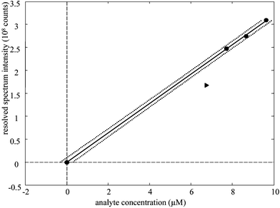 | ||
| Fig. 11 Calibration of fenvalerate via 4-way PARAFAC. Circles: calibration samples. Triangle; outlier sample. Solid line: least squares fit. Dotted lines: 3 standard deviations of prediction for a single sample. | ||
Conservative limits of detection can be estimated from the standard deviation of prediction for a single sample with no analyte in Table 1. With four-way PARAFAC applied to only the first 2 min of degradation, the estimated LOD is 3 µM. Optimistic LODs would be lower because the standard deviation of blanks are usually lower that the standard deviation about the regression. Plus, the standard deviation of prediction for a single sample includes inflation terms for the distance between the center of the calibration model and the concentration to be predicted; consequently, the LOD would be estimated lower if the calibration model were centered nearer to the graphical orgin.
4. Conclusions
Combined with the power of multi-way deconvolution methods, the EEM fluorometer shows promise for development of a photolysis-based method for environmental trace analysis of aromatic pesticides. Analyses can be performed in as little as two minutes using the fluometer source as the PID source. Analyses could potentially be even more rapid if PID accelerators (i.e., peroxide or TiO2) are employed to enhance the rate of PID. The time profiles yield a fourth dimension to the data that should increase sensitivity and selectivity of the fluorometer when analyzing complex mixtures. Because UV time profiles are characteristic of individual compounds, simultaneous photochemically induced fluorescence determinations in mixtures without pre-separation is possible. In addition, the number of fluorescent products formed is sufficiently small to permit resolution of the products from multiple analytes and the background. Application to a fluorescence probe for in-situ determination of pesticides in ground and surface waters in currently under investigation.Acknowledgements
The authors gratefully thank the National Science Foundation (OCE 0119999) for support of this work.References
- A. Coly and J. J. Aaron, Talanta, 1998, 46, 815 CrossRef CAS.
- R. D. JiJi and K. S. Booksh, Anal. Chem., 2000, 72, 718 CrossRef.
- R. D. JiJi, G. G. Andersson and K. S. Booksh, J. Chemometr., 2000, 14, 171 CrossRef CAS.
- R. D. JiJi, G. A. Cooper and K. S. Booksh, Anal. Chim. Acta, 1999, 397, 61 CrossRef CAS.
- A. M. de la Pena, A. E. Mansilla, D. G. Gomez, A. C. Olivieri and H. C. Goicoechea, Anal. Chem., 2003, 75, 2646.
- L. Moberg, G. Robertsson and B. Karlberg, Talanta, 2001, 54, 161 CrossRef CAS.
- J. L. Beltran, R. Ferrer and J. Guiteras, Anal. Chim. Acta, 1998, 373, 311 CrossRef CAS.
- M. J. Rodriguez-Cuesta, R. Boque, F. X. Rius, D. P. Zamora, M. M. Galera and A. G. Frenich, Anal. Chim. Acta, 2003, 491, 47 CrossRef CAS.
- M. G. Trevisan and R. J. Poppi, Anal. Chim. Acta, 2003, 493, 69 CrossRef CAS.
- J. C. G. E. da Silva, J. M. M. Leitao, F. S. Costa and J. L. A. Ribeiro, Anal. Chim. Acta, 2002, 453, 105 CrossRef CAS.
- R. P. H. Nikolajsen, K. S. Booksh, A. M. Hansen and R. Bro, Anal. Chim. Acta, 2003, 475, 137 CrossRef CAS.
- A. C. Olivieri, J. A. Arancibia, A. M. de la Peña, Isabel Duran-Meras and A. E. Mansilla, Anal. Chem., 2004, 76 Search PubMed , web release.
- A. Coly and J. J. Aaron, Anal. Chim. Acta, 1998, 360, 129 CrossRef CAS.
- B. M. Patel, H. A. Moye and R. Weinberger, Talanta, 1991, 38, 913 CrossRef CAS.
- J. J. Aaron and A. Coly, Analyst, 1996, 121, 1545 RSC.
- J. Ferre and N. M. Faber, 2003, 69, 123.
- R. Bro, Chemometr. Intell. Lab. Syst., 1997, 38, 149 CrossRef CAS.
- A. K. Smilde, Chemometr. Intell. Lab. Syst., 1992, 15, 143 CrossRef CAS.
- J. B. Kruskal in Multiway Data Analysis, eds. R. Coppi and S. Bolasso, Elselvier Science, Amsterdam, 1989 Search PubMed.
- N. Maniasso, E. A. G. Zagatto, S. Reis, J. L. M. Santos and J. L. F. C. Lima, Lab. Automation Inform. Manage., 1999, 143 Search PubMed.
- K. Samatha and N. Y. Sreedhar, Talanta, 1999, 49, 53 CrossRef CAS.
- E. Rodriguez, R. J. Barrio, A. Goicolea and Z. G. D. Balugera, Anal. Chim. Acta, 1999, 384, 63 CrossRef CAS.
- J. K. Mensah, E. Lundanes, T. Greibrokk and J. B. Holen, J. Chromatogr. A, 1997, 756, 85 CrossRef CAS.
- D. W. Johnson, J. B. Callis and G. D. Christian, Anal. Chem., 1977, 49, 747A CAS.
- I. M. Warner, G. D. Christian, E. R. Davidson and J. B. Callis, Anal. Chem., 1977, 49, 2155 CrossRef CAS.
- A. R. Muroski, K. S. Booksh and M. L. Myrick, Anal. Chem., 1996, 68, 3539 CrossRef CAS.
- A. R. Muroski, K. S. Booksh and M. L. Myrick, Anal. Chem., 1996, 68, 3534 CrossRef CAS.
- R. D. JiJi, M. L. Nahorniak, E. Fruitman and K. S. Booksh, SPIE Proc., 1999, 3856, 73 Search PubMed.
- D. A. Skoog, Principles of Instrumental Analysis, Saunders College Press, Philadelphia, 3rd edn., 1985 Search PubMed.
| This journal is © The Royal Society of Chemistry 2005 |