Fabrication of textured thermoelectric layered cobaltites with various rock salt-type layers by using β-Co(OH)2 platelets as reactive templates
Hiroshi Itahara*, Changtai Xia, Jun Sugiyama and Toshihiko Tani
Toyota Central Research and Development Laboratories, Inc., Nagakute, Aichi 480-1192, Japan. E-mail: h-itahara@mosk.tytlabs.co.jp; Fax: 81 561 63 6507; Tel: 81 561 63 6196
First published on 12th November 2003
Abstract
Textured bulk ceramics have been prepared of various cobaltites including the common CdI2-type CoO2 layer (i.e., [Ca2(Co0.65Cu0.35)2O4]0.624[CoO2]: CCO-4-layer, [Bi2M2−xO4]p[CoO2] (M2 = Sr2: BSCO, M2 = Ca1Sr1: B(SC)CO, M2 = Ca2: BCCO)) by using β-Co(OH)2 (CdI2-type) platelets as reactive templates, and their thermoelectric (TE) properties have been examined. All the specimens were found to be highly c-axis aligned ceramics. Especially for CCO-4-layer, B(SC)CO and BCCO, the present study is the first report on the fabrication of textured ceramics. Our textured ceramic specimens exhibited larger values of electrical conductivity (σ) than the ceramics prepared by a conventional solid-state reaction (SSR specimens): e.g., σab = 0.46 × 10⁴ S m−1 for the textured specimen and σSSR = ∼0.26 × 10⁴ S m−1 at 1060 K for the SSR specimen for BCCO. This study indicated that our preparation method using β-Co(OH)2 templates is a versatile and effective technique to fabricate cobaltites, including CoO2 layers, with a high degree of orientation and improved TE properties.
Introduction
Thermoelectric (TE) power generation for energy recovery from waste heat is expected to be an environmentally benign technology in terms of saving resources and reducing CO2 emission in to the atmosphere. The TE conversion efficiency is characterized by the figure of merit, Z ≡ σS2/κ, where σ, S and κ are electrical conductivity, Seebeck coefficient, and thermal conductivity, respectively. Thus, it is essential to develop TE materials exhibiting high σ, high S, and low κ simultaneously in order to realize highly efficient TE devices.Recently, layered cobaltites with a CoO2 layer and a block layer stacked alternately were found to show high p-type TE performance: e.g., Nax[CoO2]1 (denoted as NCO in this paper), [Ca2CoO3]0.62[CoO2]2–4 (denoted as CCO-3-layer [Ca2CoO3] is a triplicate rock salt-type (RS) layer), [Ca2(Co0.65Cu0.35)2O4]0.624[CoO2]5 (denoted as CCO-4-layer, [Ca2(Co0.65Cu0.35)2O4] is a quadruplicate RS layer), and [Bi2M2−xO4]p[CoO2] (M = Sr,6,7 Ca,8 or Ba;9 denoted as BSCO and BCCO for M = Sr and Ca, respectively; [B2M2−xO4] is a quadruplicate RS layer). Since these cobaltites are chemically stable and do not include hazardous elements such as Te, Se and Pb, the cobaltites are potential materials as TE devices to be used in air atmosphere at high temperatures.
TE properties of single crystalline particles of NCO1 and CCO-3-layer3 were reported to be highly anisotropic; i.e., the value of σ along the CoO2 layer is higher than that of the direction perpendicular to the CoO2 layer. Thus, the fabrication of textured bulk ceramics with a large value of σ would be the key technology for the application of these layered cobaltites for actual TE devices. Koumoto's group10,11 used Bi-doped CCO-3-layer single crystals synthesized by a polymerized complex method, and fabricated the textured CCO-3-layer ceramics with improved TE properties compared to a randomly oriented CCO-3-layer ceramic. Shikano and Funahashi12 prepared a textured CCO-3-layer ceramic by using flux-grown large CCO-3-layer single crystals as ingredients. However, a polymerized complex method and a flux method would be difficult to apply to industrial scale processes, because of the compositional restrictions and high production costs.
Alternatively, we have proposed the reactive templated grain growth (RTGG) method13–15 as a more convenient and effective fabrication method. Our previous studies used precipitation-prepared Co3O4 or Co(OH)2 platelets16,17 as reactive templates and indicated that the proposed method gave highly textured NCO18 and CCO-3-layer19,20 ceramics with high TE properties. We deduced that the formation mechanism of a textured CCO-3-layer ceramic would be based on the topotactic conversion: {001}Co(OH)2 → {111}Co3O4 → {001}CCO-3-layer. This is considered to be the appropriate mechanism in terms of their crystal structures; i.e., Co(OH)2, Co3O4 and CCO-3-layer have CoO2 layers composed of edge-sharing CoO6 octahedra along the {001}, {111} and {001} planes, respectively.
In the case of the misfit-layered cobaltite with a quadruplicate RS layer, the fabrication of textured ceramics is not currently well established. However, cobaltites with a quadruplicate RS layer would also exhibit a strong anisotropy in TE properties, because of their similarity to NCO and CCO-3-layer in the crystal structure. Thus, we expect that our proposed method would be a more versatile process than the others for textured TE ceramics with various compositions. In this study, we extended the RTGG method using Co(OH)2 platelets as reactive templates in the preparation of the textured ceramics of CCO-4-layer, BSCO and BCCO. In addition, we have fabricated a textured BSCO ceramic in which half of the Sr sites in the RS layer are substituted by Ca (i.e., [Bi2(Sr1Ca1)2−xO4]p[CoO2]: denoted as B(SC)CO). This paper examines the microstructures and TE properties of the RTGG-prepared ceramics, and discusses the applicability of the RTGG method for the preparation of the textured cobaltite ceramics.
Experimental
Preparation and characterization of textured ceramics
The reactive templates used in this study were β-Co(OH)2 platelets with developed {00l} planes (0.5 µm in diameter and an aspect ratio of 5),20 for which the synthesis method was reported in detail elsewhere.16Textured ceramics were prepared by the RTGG method by a similar procedure to that described in ref. 20. The high-purity powders of CuO (99.9%, Koujundo Chemical Lab. Co., Ltd.), SrCO3 (99.9%, Koujundo Chemical Lab. Co., Ltd.), Bi2O3 (99.99%, Koujundo Chemical Lab. Co., Ltd.) and CaCO3 (99.99%, Ube Material Industries, Ltd.) were used without further purification as complementary reactants. Reactive templates (β-Co(OH)2) and these reactant particles were mixed in a given ratio (see Table 1) in a ball mill for 72 ks in an ethanol–toluene solution. Then, polyvinyl butyral (binder) and di-n-butyl phthalate (plasticizer) were added to the mixture and mixed in a ball mill for another 3.6 ks. The mixed slurry was tape-cast by a doctor-blade technique, and the obtained sheets were dried in air at room temperature. The sheets (50 mm width, 80 mm length and ∼100 µm thickness) were stacked and pressed at 10 MPa at 353 K into a monolithic plate (∼3 mm thickness). Then, the organic substances in the plate were burnt out at 873 K in air for 7.2 ks. Finally, the compact was sintered at 1123–1193 K for 7.2 or 72 ks with uniaxial pressing (UPS, 1.96–19.6 MPa) in O2 atmosphere (see Table 1). In this study, the sintered specimens are denoted as RTGG-UPS specimens.
| RTGG-UPS specimena | Molar mixing ratio of starting materials | Temperatureb /K | Pressureb /MPa | Timeb /ks |
|---|---|---|---|---|
| a RTGG: reactive templated grain growth method, UPS: sinterd with uniaxial pressing.b Sintered in O2 atmosphere. | ||||
| CCO-4-layer | Co(OH)2∶CaCO3∶CuO = 4.35∶3.00∶1.05 | 1193 | 19.6 | 72 |
| BSCO | Co(OH)2∶Bi2O3∶SrCO3 = 2.00∶1.00∶2.00 | 1123 | 9.8 | 7.2 |
| B(SC)CO | Co(OH)2∶Bi2O3∶SrCO3∶CaCO3 = 2.00∶1.00∶1.00∶1.00 | 1153 | 9.8 | 7.2 |
| BCCO | Co(OH)2∶Bi2O3∶CaCO3 = 2.00∶1.00∶2.00 | 1173 | 1.96 | 7.2 |
X-Ray diffraction (XRD, Model RINT2200, Rigaku Co., Cu-Kα radiation) was conducted to determine the crystalline phases of prepared RTGG-UPS specimens. In order to determine the degree of orientation of the specimens, Lotgering's factor (f)21 was calculated using the XRD patterns, where f = (P − P0)/(1 − P0), where P = ΣI(001)/ΣI(hkl) and P0 is P for a randomly oriented powder specimen. The value of P0 for CCO-4-layer was calculated by using the reported XRD data,5 and those for BSCO, B(SC)CO and BCCO specimens were derived by the diffraction peak intensities measured for the crushed powder of RTGG-UPS specimens. The microstructures of the specimens were observed by scanning electron microscopy (SEM, Model Sigma-V, Akashi Ltd.).
Measurements of transport properties
A rectangular shape specimen, of which the longitudinal direction was parallel to the ab plane, was machined out from a textured ceramic. Electrical conductivity (σab, ab: in-plane) was measured using a four-probe method with a dc current of 2 mA. The Seebeck coefficient (Sab) was determined as the slope of the relationship between ΔV and ΔT, where ΔV is the thermoelectric voltage generated between both ends of a specimen with the temperature difference ΔT of 1–5 K. These measurements were carried out in the temperature range between 573 and 1073 K. Thermal conductivity (κab) was calculated from the relationship κab = DαCp, where D, α and Cp are the density, thermal diffusivity and the heat capacity, respectively. Here, the thermal diffusivity was estimated by the ac calorimetric method associated with the optical pulse heating.22 The figure of merit (Zab) was calculated from Zab ≡ σabSab2/κab.Results
Microstructures
Table 2 summarizes the value of f, density and open porosity for the RTGG-UPS specimens. The specimens had an open porosity of 2.3–6.9% and f of 0.673–0.954. For BSCO, B(SC)CO and BCCO (denoted as Bi-layered-cobaltites) specimens, the values of f is underestimated because the crushed powders have platelike shape so that their XRD patterns are not those of randomly oriented samples but rather slightly oriented in the {00l} plane.Fig. 1 shows the XRD pattern measured on the surface parallel to the casting plane of the CCO-4-layer (RTGG-UPS) specimen. The specimen showed strong diffraction peaks from the {00l} planes (f = 0.954). The powder XRD measurement using the crushed powder of the ceramic revealed that the specimen was nearly a single phase of CCO-4-layer with traces of Co3O4 and CCO-3-layer (data not shown here). Fig. 2 shows an SEM photograph of the fracture surface perpendicular to the casting plane of the CCO-4-layer (RTGG-UPS) specimen. The ceramic was composed of platelike grains of ∼6 µm in diameter and an aspect ratio of ∼8, aligned along the casting plane.
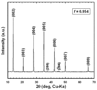 | ||
| Fig. 1 XRD pattern measured on a surface parallel to the casting plane of a CCO-4-layer (RTGG-UPS) specimen: RTGG and UPS represent ‘the reactive templated grain growth method’ and ‘sintered with uniaxial pressure’, respectively. | ||
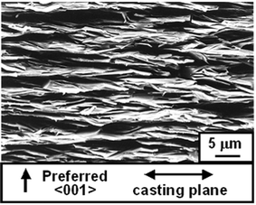 | ||
| Fig. 2 SEM photograph of a fracture surface perpendicular to the casting plane of a CCO-4-layer (RTGG-UPS) specimen: RTGG and UPS represent ‘the reactive templated grain growth method’ and ‘sintered with uniaxial pressure’, respectively. | ||
Fig. 3(a), (b) and (c) show the XRD patterns measured on the surfaces parallel to the casting plane of the BSCO, B(SC)CO and BCCO (RTGG-UPS) specimens, respectively. All the specimens showed preferred {00l} orientation. The values of f were 0.673, 0.929 and 0.831 for BSCO, B(SC)CO and BCCO (RTGG-UPS) specimens, respectively (see Fig. 3 and Table 2). Fig. 4(a), (b) and (c) show the XRD patterns measured for the crushed powers of the BSCO, B(SC)CO and BCCO (RTGG-UPS) specimens, respectively. No impurity phases were observed in all the three specimens, which could account for the formation of polycrystals with ordered compositions. In addition, the results that the d spacing of {00l} plane and the volume of RS layer shrank continuously with increasing amount of Ca would be consistent with the smaller ionic radius of Ca than that of Sr.
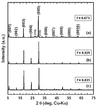 | ||
| Fig. 3 XRD patterns measured on a surface parallel to the casting plane of RTGG-UPS specimens of (a) BSCO, (b) B(SC)CO and (c) BCCO: RTGG and UPS represent ‘the reactive templated grain growth method’ and ‘sintered with uniaxial pressure’, respectively. | ||
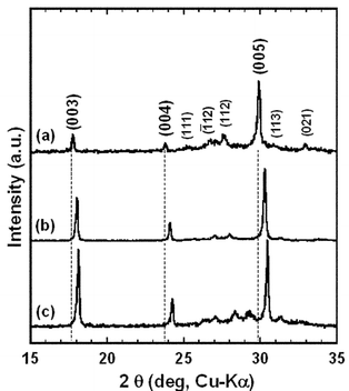 | ||
| Fig. 4 XRD patterns measured for the crushed powders of RTGG-UPS ceramic specimens of (a) BSCO, (b) B(SC)CO and (c) BCCO; RTGG and UPS represent ‘the reactive templated grain growth method’ and ‘sintered with uniaxial pressure’, respectively. | ||
Fig. 5(a), (b) and (c) show SEM photographs of the fracture surfaces perpendicular to the casting plane of the BSCO, B(SC)CO and BCCO (RTGG-UPS) specimens, respectively. It was found that the grains of BSCO (RTGG-UPS) specimen were not well aligned along the casting plane (see Fig. 5(a)), while the grains of B(SC)CO and BCCO (RTGG-UPS) specimens were almost perfectly aligned (see Fig. 5(b) and (c)). In addition, the BSCO (RTGG-UPS) specimen was composed of small grains of ∼3 µm diameter and an aspect ratio of ∼3. On the other hand, B(SC)CO and BCCO (RTGG-UPS) specimens were composed of grains with larger size and stronger anisotropy: i.e., the grains were ∼6 µm in diameter and an aspect ratio of ∼8 for B(SC)CO and ∼4 µm in diameter and an aspect ratio of ∼5 for BCCO.
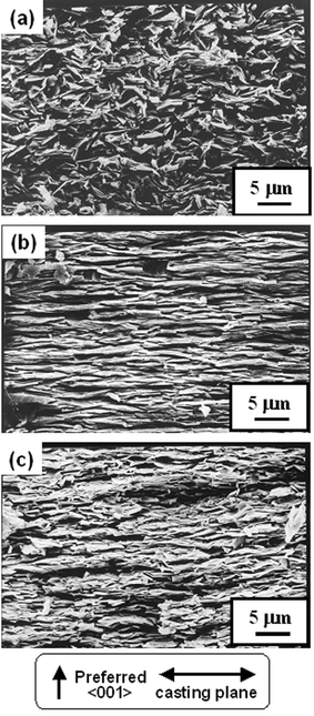 | ||
| Fig. 5 SEM photographs of the fracture surfaces perpendicular to the casting plane of RTGG-UPS specimens of (a) BSCO, (b) B(SC)CO and (c) BCCO: RTGG and UPS represent ‘the reactive templated grain growth method’ and ‘sintered with uniaxial pressure’, respectively. | ||
Transport properties
Fig. 6 shows the temperature dependences of σab and Sab measured for the CCO-4-layer (RTGG-UPS) specimen. The value of σ for the RTGG-UPS specimen is higher than that of the ceramic prepared by the conventional solid-state reaction (SSR specimen); σab = 1.48 × 10⁴ S m−1 at 550 K for the RTGG-UPS specimen, while σSSR = ∼0.62 × 10⁴ S m−1 at 300 K for the SSR specimen.5 On the contrary, the value of Sab for the RTGG-UPS specimen is comparable to that of the SSR specimen; Sab = 136 µV K−1 at 550 K for the RTGG-UPS specimen, while SSSR = ∼150 µV K−1 at 300 K for the SSR specimen.5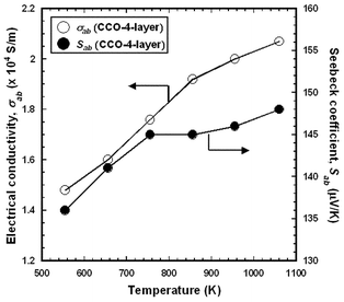 | ||
| Fig. 6 Temperature dependences of in-plane electrical conductivity (σab) and Seebeck coefficient (Sab) of CCO-4-layer (RTGG-UPS) specimen: RTGG and UPS represent ‘the reactive templated grain growth method’ and ‘sintered with uniaxial pressure’, respectively. | ||
Figs. 7 and 8 show the temperature dependences of σab and Sab for the BSCO, B(SC)CO and BCCO (RTGG-UPS) specimens. The experimental error for both measurements were less than 10%. The slope of σab for the three specimens seems to be nealy constant at temperatures between 550 and 1060 K. On the other hand, the magnitude of Sab increases with increasing Ca content in RS layers (i.e., Sab, BCCO > Sab, B(SC)CO > Sab, BSCO). This indicates that the carrier concentration in the CoO2 plane decreases with increasing Ca content.
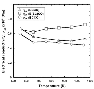 | ||
| Fig. 7 Temperature dependence of in-plane electrical conductivity (σab) of RTGG-UPS specimens of (a) BSCO, (b) B(SC)CO and (c) BCCO: RTGG and UPS represent ‘the reactive templated grain growth method’ and ‘sintered with uniaxial pressure’, respectively. | ||
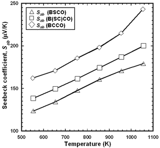 | ||
| Fig. 8 Temperature dependence of in-plane Seebeck coefficient (Sab) of RTGG-UPS specimens of (a) BSCO, (b) B(SC)CO, and (c) BCCO: RTGG and UPS represent ‘the reactive templated grain growth method’ and ‘sintered with uniaxial pressure’, respectively. | ||
In order to elucidate the effect of the alignment of the specimens, Fig. 9 shows a comparison of σ(T) and S(T) curves between RTGG-UPS and SSR specimens of BCCO. Here, SSR specimen were prepared by a conventional SSR using reagent grade Co3O4, Bi2O3 and CaCO3 as starting mterials. The values of f, density and open porosity for the SSR specimen were 0.604, 6180 kg m−3 and 5.1%, respectively. The value of σab for the RTGG-UPS specimen (0.46 × 10⁴ S m−1 at 1060 K) is about 1.8 times that of SSR specimen (0.26 × 10⁴ S m−1 at 1060 K). However, the values of Sab was found to be almost independent of the synthesis techniques. On the other hand, both σab and Sab for the present BSCO specimen, which was not well aligned, even using the RTGG method, are comparable with those of the polycrystalline specimen prepared by a conventional SSR.23
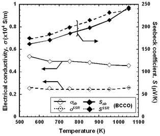 | ||
| Fig. 9 Comparison of temperature dependences of electrical conductivity (σ) and Seebeck coefficient (S) of RTGG-UPS and SSR specimens of BCCO: RTGG, UPS and SSR represent ‘the reactive templated grain growth method’, ‘sintered with uniaxial pressure’ and ‘conventional solid state reaction’, respectively. | ||
Fig. 10 shows the temperature dependences of κab for CCO-3-layer,20 CCO-4-layer, and BCCO (RTGG-UPS) specimens. The value of κab of the CCO-4-layer specimen was close to that of the CCO-3-layer specimen, while that of BCCO was about half of those of these two specimens.
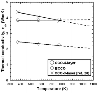 | ||
| Fig. 10 Temperature dependence of in-plane thermal conductivity (κab) of RTGG-UPS specimens of CCO-3-layer, CCO-4-layer, and BCCO: RTGG and UPS represent ‘the reactive templated grain growth method’ and ‘sintered with uniaxial pressure’, respectively. | ||
Fig. 11 shows the temperature dependence of Zab for CCO-3-layer,20 CCO-4-layer, and BCCO (RTGG-UPS) specimens. All the specimens exhibited similar value of Zab, and the values of Zab reached 1.14 × 10⁻⁴ and 1.22 × 10⁻⁴ K−1 at 1060 K for the CCO-4-layer and BCCO specimens, respectively. Here, for the calculation of Zab, the values of κab was estimated by linear extrapolation of the measured values as shown in Fig. 10.
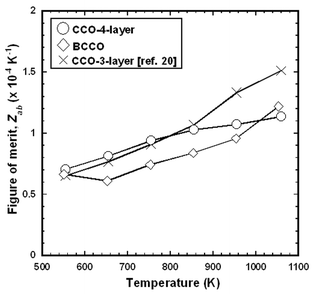 | ||
| Fig. 11 Temperature dependence of in-plane figure of merit (Zab) of RTGG-UPS specimens of CCO-3-layer, CCO-4-layer, and BCCO: RTGG and UPS represent ‘the reactive templated grain growth method’ and ‘sintered with uniaxial pressure’, respectively. | ||
Discussion
Formation of textured cobaltite ceramics
The cobaltites with quadruplicate RS layers were prepared with the maintained orientation of β-Co(OH)2 platelets as shown in Figs. 1, 2, 3 and 5. In the previous studies,19,20 we deduced the formation mechanism of a textured CCO-3-layer ceramic as follows. First, β-Co(OH)2 decomposes into Co3O4, which has a layer composed of edge-sharing CoO6 octahedra (denoted as layer A) and a layer composed of CoO6 octahedra and CoO4 tetrahedra (denoted as layer B). In the next transformation, the layer A is maintained to form the CoO2 layer of CCO-3-layer, while the layer B reacts with complementary elements, Ca and O, to form the RS layer of CCO-3-layer.In the case of CCO-4-layer, its formation mechanism might be similar to that of CCO-3-layer because of the similarity in their crystal structures: i.e., the layer A maintains to form the CoO2 layer and the layer B reacts with Ca, Cu and O to form the RS layer. The lower value of f for CCO-4-layer (0.954) than that of CCO-3-layer (>0.9920) may be attributed to the larger distance between CoO2 layers due to the larger size of RS layers of CCO-4-layer (1.267 nm) than that of CCO-3-layer (1.084 nm) and the distance between the A layers of Co3O4 (0.8084 nm).
In contrast, the formation mechanisms of Bi-layered-cobaltites could be different from those of CCO-3-layer and CCO-4-layer since there would be practically no Co in the RS layer in their system. A significant atomic reconstruction must accompany the formation reaction of Bi-layered-cobaltites even if the layer A and/or B of Co3O4 serve to form a CoO2 layer with the maintained orientation. In addition, the ingredient Bi2O3 (mp ∼1123 K), provides a liquid-phase which might cause rearrangement of grains and disturb the texture.24 The assumptions mentioned above could account for the lower values of f (0.673–0.929: see Fig. 3) of Bi-layered-cobaltites than those of CCO-3-layer (>0.9920) and CCO-4-layer (0.954). On the other hand, the reasons for the large differences in f among Bi-layered-cobaltites (i.e., B(SC)CO (0.929) > BCCO (0.831) > BSCO (0.673) as shown in Fig. 3) are currently unkown.
The RTGG method using β-Co(OH)2 was found to give textured ceramics of various layered cobaltites with CoO2 layers. In future studies, it is necessary to clarify the conversion mechanisms for preserved orientation.
Transport properties
The values of σ of CCO-4-layer (RTGG-UPS) and BCCO (RTGG-UPS) were higher than that of SSR specimens (see refs. 5 and 8 and Fig. 9). These results are consistent with the previous study for CCO-3-layer, and probably due to the reduction in the electron scattering at grain boundaries. On the other hand, the RTGG-UPS specimens of CCO-4-layer, BSCO and BCCO exhibited similar S for SSR specimens (see refs. 5, 8 and 23 and Fig. 9) These results are consistent with the report that the dependence of S on the degree of orientation is small.10,19,20The values of S for the Bi-layered-cobaltites were Sab, BCCO > Sab, B(SC)CO > Sab, BSCO (Fig. 8). The possible interpretation is that the volume shrinkage in the RS layers causes the emission of excess oxygen and a decrease in valence of Co ions in the CoO2 layer thereby resulting in a decrease of the carrier density. The other possibility is that Co would enter in the RS layers in the case of B(SC)CO and BCCO because the ionic radius of Co ion (Co3+: 0.065 nm25) is closer to Ca2+ (0.0100 nm25) and/or Bi3+ (0.0103 nm25) than Sr2+ (0.0118 nm25). Such replacement in the position of Co ions would induce the change in carrier deisity of the CoO2 plane. In order to further understand the change in TE properties, it is necessary to examine the valence of Co ions by Hall mobility measurements.
Finally, BCCO has a lower value of κab than CCO-4-layer and CCO-3-layer (Fig. 11). It is expected that the heavy Bi element and weak Bi–O bonds would suppress the lattice vibration.
The present study indicates that the RTGG method using β-Co(OH)2 platelets is a versatile and effective method to prepare textured ceramics of various cobaltites with improved TE properties. It is important to clarify the conversion mechanisms through in-situ crystallographic analyses and optimal fabrication conditions found for the fabrication of ceramics with improved texture.
Conclusion
We have fabricated the textured cobaltites composed of a CoO2 layer and quadruplicate rock salt-type layer (i.e., [Ca2(Co0.65Cu0.35)2O4]0.624[CoO2]: CCO-4-layer, [Bi2M2−xO4]p[CoO2] (M2 = Sr2: BSCO, M2 = Ca1Sr1: B(SC)CO, M2 = Ca2: BCCO) by using β-Co(OH)2 platelets as templates. All the ceramic specimens (RTGG-UPS specimens) were c-axis aligned ceramics of nearly single-phase and the values of f were 0.954, 0.673, 0.929 and 0.831 for CCO-4-layer, BSCO, B(SC)CO and BCCO, respectively. It was shown that textured ceramics with high value of f would result in higher values of σ than the ceramics prepared by the conventional solid-state reaction (SSR specimens). On the other hand, the values of S of RTGG-UPS specimens were comparable to those of SSR specimens, which reflects the small anisotropy in S. The values of Zab reached 1.14 × 10⁻⁴ and 1.22 × 10⁻⁴ K−1 at 1060 K for the CCO-4-layer and BCCO specimens, respectively. In conclusion, our preparation method using β-Co(OH)2 platelets is a versatile and effective method to prepare textured ceramics of various cobaltites with improved TE properties.Acknowledgements
We would like to acknowledge Drs R. Asahi and Y. Seno of Toyota CRDL for their helpful discussion. H. Itahara would like to acknowledge Prof. K. Koumoto of Nagoya Univ. and Dr A. Maignan of Caen Univ. for discussions on the layered cobaltites. This work was partly carried out by joint research and development with the International Center for Environmental Technology Transfer in 2002–2003, commissioned by the Ministry of Economy, Trade and Industry.References
- I. Terasaki, Y. Sasago and K. Uchinokura, Phys. Rev. B., 1997, 56, R12685 CrossRef CAS.
- S. Li, R. Funahashi, I. Matsubara, K. Ueno and H. Yamada, J. Mater. Chem., 1999, 9, 1659 RSC.
- A. C. Masset, C. Michel, A. Maignan, M. Hervieu, O. Toulemonde, F. Studer and B. Raveau, Phys. Rev. B, 2000, 62, 166 Search PubMed.
- Y. Miyazaki, M. Onoda, T. Oku, M. Kikuchi, Y. Ishii, Y. Ono, Y. Morii and T. Kajitani, J. Phys. Soc. Jpn., 2002, 71, 491 Search PubMed.
- Y. Miyazaki, T. Miura, Y. Ono and T. Kajitani, Jpn. J. Appl. Phys., 2002, 41, L849 CrossRef CAS.
- R. Funahashi, I. Matsubara and S. Sodeoka, Appl. Phys. Lett., 2000, 76, 2385 CrossRef CAS.
- H. Leligny, D. Grebille, O. Pérez, A. C. Masset, M. Hervieu and B. Raveau, Acta Crystallogr., Sect. B, 2000, 56, 173 CrossRef.
- A. Maignan, S. Hébert, M. Hervieu, C. Michel, D. Pelloquin and D. Khomskii, J. Phys.: Condens. Matter, 2003, 15, 2711 CrossRef CAS.
- M. Hervieu, A. Maignan, C. Michel, V. Hardy, N. Créon and B. Raveau, Phys. Rev. B, 2003, 67, 45112 Search PubMed.
- J-W. Moon, D. Nagahama, Y. Masuda, W-S. Seo and K. Koumoto, J. Ceram. Soc. Jpn., 2001, 109, 647 CAS.
- Y. Masuda, D. Nagahama, H. Itahara, T. Tani, W-S. Seo and K. Koumoto, J. Mater. Chem., 2003, 13, 1094 RSC.
- M. Shikano and R. Funahashi, Appl. Phys. Lett., 2003, 82, 1851 CrossRef CAS.
- T. Tani, J. Korean Phys. Soc., 1998, 32, S1217 Search PubMed.
- T. Takeuchi, T. Tani and Y. Saito, Jpn. J. Appl. Phys., 1999, 38, 5553 CrossRef CAS.
- T. Tani, S. Isobe, W.-S. Seo and K. Koumoto, J. Mater. Chem., 2001, 11, 1 RSC.
- H. Itahara, S. Tajima and T. Tani, J. Ceram. Soc. Jpn., 2002, 110, 1048 CAS.
- C. Xia, H. Itahara, J. Sugiyama and T. Tani, J. Ceram. Soc. Jpn. Search PubMed , submitted.
- S. Tajima, T. Tani, S. Isobe and K. Koumoto, Mater. Sci. Eng. B, 2001, 86, 20 Search PubMed.
- T. Tani, H. Itahara, C. Xia and J. Sugiyama, J. Mater. Chem., 2003, 13, 1865 RSC.
- H. Itahara, C. Xia, Y. Seno, J. Sugiyama, T. Tani and K. Koumoto, Proceedings of 22nd International Conference on Thermoelectrics, La Grande Motte, 2003, in press Search PubMed.
- F. K. Lotgering, J. Inorg. Nucl. Chem., 1959, 9, 113 CrossRef CAS.
- T. Yamane, S. Katayama and M. Todoki, Rev. Sci. Instrum., 1995, 66, 5305 CrossRef CAS.
- G. Xu, R. Funahashi, M. Shikano, I. Matsubara and Y. Zhou, J. Appl. Phys., 2002, 91, 4344 CrossRef CAS.
- H. Itahara, K. Fujita, J. Sugiyama, T. Tsukada and T. Tani, Proceedings of 22nd International Conference on Thermoelectrics, La Grande Motte, 2003, in press Search PubMed.
- R. D. Shannon, Acta Crystallogr., Sect. A, 1976, 32, 751 CrossRef.
| This journal is © The Royal Society of Chemistry 2004 |
