Pulsed laser ablation and deposition of thin films
Michael N. R.
Ashfold
,
Frederik
Claeyssens
,
Gareth M.
Fuge
and
Simon J.
Henley
School of Chemistry, University of Bristol, Bristol, UK BS8 1TS
First published on 6th August 2003
Abstract
Pulsed laser ablation is a simple, but versatile, experimental method that finds use as a means of patterning a very diverse range of materials, and in wide areas of thin film deposition and multi-layer research. Superficially, at least, the technique is conceptually simple also, but this apparent simplicity hides a wealth of fascinating, and still incompletely understood, chemical physics. This overview traces our current physico-chemical understanding of the evolution of material from target ablation through to the deposited film, addressing the initial laser–target interactions by which solid material enters the gas phase, the processing and propagation of material in the plume of ejected material, and the eventual accommodation of gas phase species onto the substrate that is to be coated. It is intended that this Review be of interest both to materials scientists interested in thin film growth, and to chemical physicists whose primary interest is with more fundamental aspects of the processes of pulsed laser ablation and deposition.
 Michael N. R. Ashfold Michael N. R. Ashfold | Mike Ashfold is a Professor of Physical Chemistry at the University of Bristol. He obtained BSc and PhD degrees from the University of Birmingham, and was a Guy Newton Junior Research Fellow at Oxford University, prior to a faculty appointment at Bristol in 1981, promotion through the ranks and appointment to a Chair in 1992. His research achievements in broad areas of gas phase and gas-surface chemistry have been recognised by a number of awards including the RSC Marlow (1987), Corday-Morgan (1989) and Tilden (1996) medals and prizes, and the RSC Industrially-sponsored Award in Spectroscopy (2000). He was a Visiting Fellow at the Joint Institute for Laboratory Astrophysics, University of Colorado in 1990, a Royal Society Leverhulme Trust Senior Research Fellowship for 1994/5 and was awarded an EPSRC Senior Research Fellowship for the period 1997–2002. |
Frederik Claeyssens is a Post-doctoral Research Assistant in chemistry at the University of Bristol. He obtained his licentiate in chemistry degree from the University of Ghent (Belgium) and his PhD degree from the University of Bristol. His PhD work involved pulsed laser ablation and deposition of graphite/diamond-like-carbon (DLC) and zinc oxide. He is currently involved in computational materials science, in collaboration with the laser ablation group at Bristol University. |
Gareth Fuge obtained a BSc in chemical physics in 2001 and is currently studying for a PhD in the School of Chemistry at the University of Bristol. His current research is on the structural, optical and electrical characterisation of undoped and doped DLC thin films (and also alloys of C, P, O, N) deposited by Pulsed Laser Deposition. His previous research includes PLA of graphite in N2 depositing CNx thin films with a view to producing mechanically hard thin films with improved electrical conductivity. |
Simon Henley completed his PhD in the Physics Department of the University of Bristol in 2001. During this period his main area of research involved study of the effect of defects, such as dislocations, on the luminescence efficiency of GaN based optoelectronic materials. He is currently employed in a joint Chemistry/Physics DTI LINK OSDA sponsored collaborative project to develop field emission displays and is involved in fundamental research into pulsed laser ablation and deposition of multi-component materials such as ZnO and LiF. |
Introduction
First reports of the use of pulses of laser radiation to remove, or ‘ablate’, material from a solid (or liquid) target followed close on the heels of the first ruby lasers becoming available in the early 1960s. Given the obvious efficiency of the material ablation process, it was but a short step before pulsed laser ablation was first employed as a route to thin film deposition.1 Pulsed laser ablation (PLA) has evolved in many directions during the intervening period, such that it now impacts across broad swathes of contemporary science, medicine and engineering. This outreach has been driven, in part, by technological developments – notably the progressive improvements in the generation of reliable, high intensity pulsed laser radiation. Milestones of note in this area include the successful implementation of reliable Q-switching methods, the development of new, pulsed laser sources (e.g. nanosecond pulsed Nd-YAG and excimer lasers) and, more recently, the increased availability of intense pico- and femto-second pulses. Equally important, however, has been the enormous diversity of the uses to which pulsed laser ablation methods have been applied. Film deposition, a focus of the present review, is but one.2,3 Laser ablation methods also find widespread use in the micro-structuring and patterning of polymers and wide band gap materials like silicon and fused silica, in removal of biological (e.g. corneal) tissue,4 and are now even being applied to surface cleaning of delicate artwork.5 The realisation that laser ablation methods could provide a means of ejecting intact molecules – even large biomolecules – into the gas phase helped spawn novel analytical techniques like matrix assisted laser desorption/ionisation (MALDI) which has now come to be seen as essential in broad areas of the life sciences. Much of this diversity has been captured in a series of articles in a recent issue of Chemical Reviews devoted to the laser ablation of molecular substrates.6The Introduction to that collection of articles posed the question as to why, given the numerous applications of the technique, few if any comparable overviews had appeared previously? Two possible explanations were suggested. Firstly, it was argued that the self-evident applicability of the technique, and the diversity of these applications, had encouraged scientists to focus on these, rather than seeking a fundamental understanding of the ablation and deposition processes themselves.6 Secondly, the processes are complex. At a superficial level, ablation might be viewed simply as a rapid boiling of material within a localised interaction volume at, and close to, the surface of the target. When investigated more deeply, however, the hidden complexity soon becomes apparent. Much of this complexity is illustrated, schematically, in Fig. 1. The incident laser pulse induces extremely rapid heating of a significant mass/volume of target material. This may cause phase transitions, and introduce high amplitude stress waves in the solid target. Material will start to boil off and expand into the gas phase. Is material ejection driven solely by thermal processes, or can photochemical (electronic) mechanisms contribute also? Material ejection begins on a picosecond timescale. Thus, unless one is working with very short duration laser pulses, the ensuing plume of ejecta will be irradiated by the later part of the incident laser pulse. This radiation will, in many cases, be absorbed by the plume, leading to an attenuation of the light intensity incident on the target and excitation and ionisation of species in the plume. Plasma formation and subsequent optical emission will result. Ionisation in, and emission from, the plume are obvious measurables, but what do such measurements actually reveal about the detailed photophysics of the ablation process itself? After cessation of the laser pulse, the target will cool and resolidify. The plume, which now consists of an ensemble of neutral and charged material, carrying varying levels of residual (and time decaying) excitation, will continue to expand away from the interaction volume. What determines the relative number densities of the different components? What are their respective velocity distributions? Do these affect the characteristics of any film deposited on any substrate mounted within the expanding plume of ejected material? The present article reviews the current state of understanding of some of these fundamental physico-chemical aspects of pulsed laser ablation and deposition, viewed from the perspectives of, respectively, the target, the plume and the deposited film.
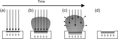 | ||
| Fig. 1 Schematic illustrating key elements of the PLA event. (a) Initial absorption of laser radiation (indicated by long arrows), melting and vaporization begin (shaded area indicates melted material, short arrows indicate motion of solid–liquid interface). (b) Melt front propagates into the solid, vaporization continues and laser-plume interactions start to become important. (c) Absorption of incident laser radiation by the plume, and plasma formation. (d) Melt front recedes leading to eventual re-solidification. | ||
As Fig. 2 illustrates, the basic pulsed laser ablation (PLA) and deposition (PLD) experiment can be constructed relatively simply. The output of a pulsed laser is focused onto a target material maintained in a vacuum, typically better than 10−6 Torr in the experiments discussed herein, or in a low pressure of background gas. The target is usually rotated, or rastered, in order to avoid repeated ablation from the same spot on the target. Rastering is preferred from the viewpoint of most efficient use of the prepared target surface. Lasers used in PLD studies range in output wavelength from the mid infrared (e.g. a CO2 laser, 10.6 µm), through the near infrared and visible (e.g. the Nd-YAG laser, with fundamental and second harmonic outputs at 1064 nm and 532 nm, respectively) and down into the ultraviolet (UV). Much current PLD work employs excimer lasers, which operate at a number of different UV wavelengths (e.g. 308 nm (XeCl), 248 nm (KrF), 193 nm (ArF) and 157 nm (F2)). The ejected plume of plasma and neutral material expands away from the interaction volume; its distribution is generally symmetric about the target surface normal. For PLD, the ejected flux is arranged to impinge on the substrate of interest, and film deposition occurs. The growth and quality of the resulting film will generally depend on a number of fundamental parameters, including the choice of substrate, the substrate temperature, Tsub, and the absolute and relative kinetic energies and/or arrival rates of the various constituents within the plume. The latter may be affected by the choice of excitation wavelength, by the laser pulse duration, energy and intensity, by the presence (or otherwise) of any background gas, and by any secondary plasma activation in the target–substrate gap.3,7
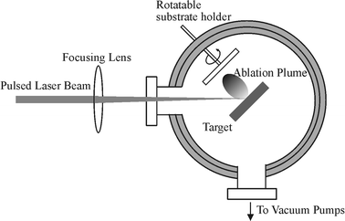 | ||
| Fig. 2 Schematic diagram of an apparatus for PLA of a solid target with deposition on an on-axis mounted substrate. | ||
The target
We start by considering some of the mechanisms that can contribute to material loss following irradiation of the target with a pulse of photons. Following Kelly and Miotello,8 these are generally sub-divided into primary and secondary processes. Suggested sub-divisions of the former include thermal, electronic and macroscopic sputtering; their relative importance will depend on the nature of the target material, and on the laser excitation wavelength and pulse duration, and the distinctions between them are often not particularly clear-cut. That there should be electronic (or photochemical) contributions to the ablation of molecular materials, like polymers, which contain well-defined chemical bonds, is unsurprising.6 Direct evidence for electronic sputtering contributions in the case of metals and other extended solids is generally harder to discern, but reported examples include the observation of atoms with markedly non-thermal velocity distributions arising in laser-induced desorption from nano-sized metal particles9 and from thin metallic films10 (both of which findings have been attributed to surface–plasmon interactions) and even of graphite targets.11Most detailed mechanistic considerations of target excitation and sputtering involve electronic initiation. Material interaction with an ultra-short laser pulse is assumed to involve very rapid excitation of the electron distribution, with efficient electron–electron coupling leading to an immediate rise in the electron temperature, subsequent heating of the lattice at a rate dependent upon the electron–phonon coupling strength, and eventual vaporization of the transiently heated target. Electronic contributions will thus tend to be most evident when using very short (i.e. sub-picosecond) pulse durations, and can manifest themselves as unexpectedly large ion yields and/or supra-thermal propagation velocities within the expanding plasma plume. Thermal contributions will generally dominate when using longer (e.g. nanosecond duration) laser pulses, of sufficient duration to allow photon coupling with both the electronic and vibrational modes of the target material. Such thermal contributions will be most favoured in cases where the target has low reflectivity (at the laser wavelength), a large absorption coefficient (thus ensuring that the optical penetration depth is small), a low thermal diffusion coefficient and comparatively low boiling point, Tb. Since Tb will always exceed the target melting temperature, Tm, evidence of wavelike structures on the post-irradiated target surface – indicative of localized melting – is often sought as confirmatory evidence for there being a thermal contribution to the ablation yield. Fig. 3 shows scanning electron microscope (SEM) images of copper (Tm = 1356 K, Tb = 2833 K) and graphite targets, both before and after exposure to 3 pulses of ArF laser radiation. The frozen wavelike surface topology and the indications of partially formed droplets provide clear evidence for thermal contributions to the 193 nm PLA of Cu. In the case of carbon, the location and extent of the liquid domain within its phase diagram, was a subject of longstanding debate. Traditional heating techniques proved difficult to apply at the necessary high Tm values and some of the clearest of the early demonstrations for a liquid phase of carbon, and its physical properties, came from laser induced melting studies of graphite or diamond.12,13 The observation that the SEM image of the graphite target, post-ablation (Fig. 3(d)), is noticeably smoother is wholly consistent with graphite having a molten phase. So, too, is the finding that the laser Raman spectra of the surfaces of post-ablated graphite and polycrystalline diamond targets are essentially indistinguishable.14
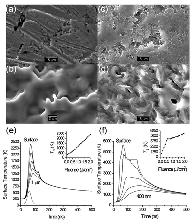 | ||
| Fig. 3 SEM images of different elemental targets pre- and post-ablation at 193 nm with 3 laser shots at a fluence of 10 J cm−2: (a) Cu pre-ablation and (b) post-ablation. (c) Graphite pre-ablation and (d) post-ablation. Also shown are the results of model calculations illustrating the time dependence of the surface temperature, TS, and the temperature at a number of different penetration depths, D, within the localised laser interaction zone for (e) copper (D varied in 250 nm steps from 0 to 1 µm) and (f) graphite (D varied in steps of 100 nm from 0 to 400 nm). The incident laser pulse used in these calculations is assumed to have a Gaussian temporal profile of 30 ns FWHM and to peak 60 ns after the start of the simulation, as shown at the bottom of (e). Optical and thermodynamic constants for graphite and copper, chosen to mimic their interaction with a 193 nm laser pulse, are taken from refs. 13 and 15, respectively. | ||
Also shown in Figs. 3(e) and 3(f) are the results of model calculations employing a 1-D second-order heat conduction model (defined in ref. 15) illustrating the time dependence of the surface temperature (TS), and the temperature at a number of different penetration depths, D, within the localised laser interaction zone. The incident laser pulse used in these calculations is assumed to have a Gaussian temporal profile of 30 ns full width half maximum (FWHM) and to peak 60 ns after the start of the simulation. Optical constants and physical properties for both materials, chosen to mimic their interaction with a 193 nm laser pulse, were taken from refs. 13 (graphite) and 15 (copper). The temperature within the irradiated volume rises rapidly because the laser heating rate far exceeds the rate of thermal diffusion and radiative losses. In both cases, the surface temperature is found to exceed the melting temperature at relatively low laser fluences; the calculated melting threshold fluences are 0.6 J cm−2 (for highly oriented pyrolitic graphite) and 1.1 J cm−2 (for copper). Additionally, the temperature gradient within the two materials is seen to reflect their respective thermal conductivities. The thermal conductivity of copper is some two orders of magnitude higher than that of graphite, so heat transfer into the bulk of the material occurs much faster in the case of Cu.
The material ejection mechanism and the total amount of ejected flux can change dramatically when the fluence increases sufficiently to induce explosive boiling of the target material. This process, sometimes referred to as phase explosion,16 occurs at temperatures approaching the critical point, Tc. It is viewed as an explosive relaxation of the laser induced melt into a co-existent mixture of liquid droplets and vapour. Such hydrodynamic ejection of droplet-like particulates is one illustration of macroscopic sputtering. Exfoliation, whereby macroscopic flakes detach from the target as a result of the repeated thermal shocks, is another. This type of sputtering can arise when using target materials having high thermal expansion coefficients and a sufficiently high melting point that the thermal oscillations induced by repeated pulsed laser excitation do not exceed Tm. Macroscopic particulate ejection can also arise in the case of porous targets, wherein the localised laser induced heating will cause very rapid expansion of any trapped gas pockets just below the surface and forcible ejection of the surface material.
In contrast to ion bombardment, simple momentum transfer from an incident photon provides nothing like enough energy to dislodge an atom from the target surface. Pulsed laser irradiation can lead to a number of indirect, or secondary, collision effects, however. Consider the case of UV PLA of graphite targets – a favoured route to depositing hydrogen-free hard diamond-like carbon (DLC) films with an unusually high sp3 bonding fraction.17 DLC films, which are hard and smooth, generally inert, exhibit low friction and adhere well to many substrates, find widespread use as wear resistant coatings. Target weight loss measurements show that, under our typical operating conditions (incident fluence ∼20 J cm−2, ∼20 ns pulse duration), ∼1015 C atoms (or their mass equivalent) are removed per pulse. It is worth pausing for a moment to consider the consequences of this number. Surface profilometry indicates that the excimer laser beam focuses to a spot size of ∼0.4 mm2 on the graphite target. Assuming uniform removal of material from this area, 1015 atoms translates into an etch depth of ∼3 nm (or some 10 monolayers) per pulse. What happens to the ablated material? Each ejected particle will have some velocity vx > 0, where vx is the velocity normal to the target surface. If the density of ablated material is sufficiently low, these particles will undergo collision free expansion away from the interaction volume with a velocity distribution that is characteristic of the primary ablation process (e.g. a Maxwellian distribution in the case of a true thermal sputtering process). Such is far from the case, however, if 1015 atoms are ejected during a 20 ns laser pulse. If we assume a mean plume expansion velocity of ∼ 20 km s−1, we can estimate that at the end of this laser pulse the ablated material will be confined within a volume of ∼ 0.13 mm3; i.e. that the local pressure easily exceeds 1 bar! Clearly, this pulse of ejected material continues to expand, but collisions in the early stages of the expansion (in the so called Knudsen layer) are sufficiently frequent that the particle velocities approach equilibrium. The ensemble of particle velocities takes the form of a ‘shifted’ Maxwellian
| P(vx) ∼ vx3exp[−m(vx − u)2/2kT] | (1) |
Close inspection of target samples, post-ablation, often reveals a spectacular array of cone-shaped asperities such as those shown in Fig. 4, for the particular case of an ArF laser ablated MgB2 target. Such cone formation is frequently observed in targets that have been subjected to ion bombardment, and has been explained in terms of position dependent erosion probabilities such as might arise in the case of an inhomogeneous solid target, with sputter resistant ‘impurities’ surviving at the cone tips. By analogy, some authors16 have thus argued that cone formation observed in PLA must have similar origins, and that this therefore provides evidence for secondary particle induced target sputtering. An alternative, and generally more widely accepted view, however, is that the cones arise from preferential ablation of all surface areas bar those shielded by vaporization resistant inhomogeneities.19 Such inhomogeneities may be naturally occurring, or laser induced. It may be significant that many of the reported examples of laser induced cone formation have involved compound (e.g. MgB2 or YBa2Cu3O7−δ (YBCO)), rather than elemental, targets.20 Laser irradiation in such cases may induce localised changes in surface composition (due to preferential ablation or selective re-deposition of one constituent) and/or in morphology (e.g. the formation of re-solidified or re-crystallised asperities, or by the re-deposition of ablation debris) that can serve as the ablation resistant nuclei that survive to become the tips of the eventual cones. The evident alignment of the cones, and the observation that their long axes are generally parallel with the propagation direction of the laser pulse, are both consistent with such a view.
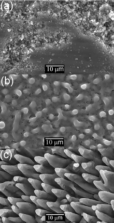 | ||
| Fig. 4 SEM images of an MgB2 target ablated at 193 nm at a fluence of 12 J cm−2. (a) Pre-ablation, (b) after ablation with one pulse and (c) after ablation with 10 pulses. | ||
Many reported laser ablation experiments are conducted in low pressures of background gas (which may, in some cases, be activated by a secondary plasma) rather than in vacuum. Clearly, new chemistry becomes possible given the presence of an appropriate background gas but, from the perspective of the target, the main effects of background gas will be to constrain the expansion of the plume of ejected material, higher gas phase number densities in the very early stages of plume expansion, and an enhanced probability of material re-deposition onto the target surface.
The plume
A luminous plume of plasma will be apparent at the kind of fluences, F, typically required when using PLA for film growth (i.e. deposition rates >0.1 nm pulse−1). The intense ‘white’ continuum emission observed very close to the target is Bremsstrahlung, associated with free–free transitions within the hot plasma. After expanding to distances of a few mm PLA plumes usually exhibit many atomic neutral and ionic lines. Fig. 5, which shows wavelength dispersed spectra of the plume emission accompanying graphite ablation at 193 nm, in vacuum,21 provides a good illustrative example. Analysis reveals that electronically excited C atoms and C+ ions (henceforth indicated as C* and C+*, respectively) are responsible for essentially all of the emissions in the wavelength range 250–1000 nm. Weak lines attributable to C2+* ions are observed at high F and small distances, d, from the target – under which conditions the ratio of the C+*/C* emission intensities is also maximal. Spectra (a) and (b) were recorded by viewing down a column perpendicular to the plane depicted in Fig. 2, at d = 7 and 20 mm along the line bisecting the laser propagation axis and the target surface normal. Both ionic and neutral atomic carbon emissions are evident in these spectra. The latter are indicated by the comb above Fig. 5(a), while the remaining unassigned lines originate from electronically excited C+ ions. Comparison of these two spectra shows the ionic emissions decaying faster than the neutral lines with increasing d. Spectrum (c) was also recorded at d = 7 mm, but with the viewing column localised on the opposite side of the plume from the incident laser beam. In this case only neutral C* lines are observed, indicating that the more persistent C+* features evident in Fig. 5(a) are largely attributable to laser-plume interactions.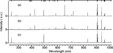 | ||
| Fig. 5 Wavelength dispersed spectra of the plume emission accompanying 193 nm PLA of a graphite target in vacuum, using F ∼ 20 J cm−2 laser pulses incident at 45° to the surface normal. Spectra (a) and (b) were recorded through a viewing column perpendicular to the plane depicted in Fig. 2, at d = 7 and 20 mm along the line bisecting the laser propagation axis and the target surface normal. Ionic and neutral atomic carbon emissions are evident in these spectra; the comb above Fig. 5(a) identifies transitions of the latter, while the remaining unassigned lines originate from electronically excited C+* ions. Spectrum (c) was also recorded at d = 7 mm, but with the viewing column localised on the opposite side of the plume from the incident laser beam. Only neutral C* lines contribute to this spectrum. | ||
Analogous spectra recorded when using longer ablation wavelengths and/or high background pressures show emissions from C* atoms and from small molecular species – e.g. C2*, or CN* when using low pressures of N2 as the background gas. We will return to a more detailed consideration of the mechanisms by which these excited species may be formed, their decay, and the information that can be derived by monitoring such emissions. Even at this stage, however, these data serve to illustrate some general features of the plumes arising in PLA processes. For example, it is clear that the plume contains neutral and ionic species and, by charge conservation, electrons. These various constituents have been investigated, in plumes arising from PLA of many different targets, by a wide variety of methods – including optical emission, absorption, ion probe measurements and mass spectroscopy (MS).
Few polyatomic species are observable via optical emission spectroscopy (OES), as excited electronic states of such species usually find alternative, and more efficient, non-radiative decay mechanisms. Absorption methods are also of limited applicability for such species, on account of spectral congestion. Optical methods are thus most widely used for monitoring atomic and simple diatomic species in ablation plumes. Ion probe methods clearly show that the degree of ionisation within the plume generally increases non-linearly as the incident intensity is raised, and is greater when the target material has a low ionisation potential, Ei (e.g. a metal), but they suffer the limitation that they are rarely mass (and thus species) selective. Arguably, therefore, mass spectroscopy has been of greatest use in providing information about the larger molecular species, clusters and particulates present in ablation plumes. For example, MS analysis of the plumes accompanying 1064 nm and 532 nm PLA of YBa2Cu3O7−x (YBCO), in vacuum, reveals extensive cluster ion formation at low incident fluences but that, at higher F, the relative yield of these high mass ions declines to zero – presumably because they are photolysed within the ablating laser pulse.22 Time-of-flight (TOF) MS can also be used to determine neutral and ion velocities within the expanded plume, i.e. far from the target. Close to the target the electron and ion densities are too high, and the Debye length too short, for MS to be a useful diagnostic.22 Such measurements consistently reveal that the ions and neutrals have very different velocity distributions; the former are much ‘hotter’.
Optical emission measurements yield similar conclusions. The left hand column in Fig. 6, for example, shows images of wavelength selected C+* and C* emissions arising in the 248 nm PLA of graphite, in vacuum, using nanosecond duration laser pulses, recorded using an intensified charge coupled device (i-CCD) camera. To record these particular images, the intensifier was gated ‘on’ for Δt = 20 ns, at t = 380 ns after the ablating pulse was incident on the target.23 Clearly, both distributions of emitting species are symmetrically distributed about the surface normal, but the centre of gravity of the C+* emitters has propagated considerably further during this time. Numerous optical emission, ion probe and MS studies have confirmed the generality of the finding that the distribution of material ejected in a PLA experiment is generally peaked along the surface normal, and falls off as cosqθ, where θ is the angle measured away from the surface normal.24 This follows directly from the fact that the distribution of material in the plume has a finite flow velocity along x, (eqn. (1)). Analysis of images such as those shown in Figs. 6(a) and (b) can yield estimates of the axial (i.e. along x) and transverse (i.e. perpendicular to x) components of the respective velocity distributions.23 Such analyses, though informative, are generally not exact, since the images are squashed 2-D projections of the full 3-D cloud of emitting particles. In the illustrated example, image analysis suggests that the distributions of C+* and C* species propagate along the surface normal with mean velocities u ∼ 43 and ∼17 km s−1, respectively, with axial (δvx) and transverse (δv⊥) full width half maximum (FWHM) velocity spreads of ∼15 and ∼46 km s−1 (for C+*) and ∼17 and ∼31 km s−1 (for C*).
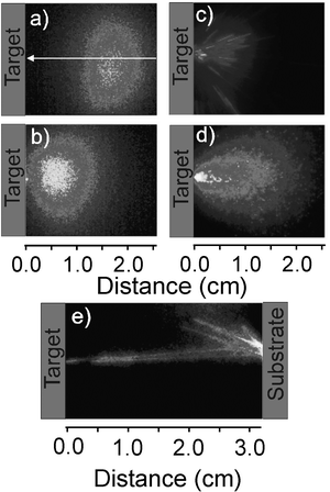 | ||
| Fig. 6 i-CCD images of wavelength selected (a) C+* and (b) C* emissions accompanying 248 nm PLA of a graphite target in vacuum, using ns laser pulses at F ∼ 10 J cm−2, recorded using a time gate on the intensifier Δt = 20 ns delayed by t = 380 ns relative to the ablation pulse striking the target. The white arrow in (a) indicates the axis of the incident laser beam. (c)–(e) show i-CCD images of the total emission from particulates formed in the 248 nm PLA of graphite using 450 fs laser pulses. These latter images were obtained using the following intensifier gate timings: (c) Δt = 50 µs, t = 60 µs; (d) Δt = 1 µs, t = 130 µs; and (e) Δt = 500 µs, t = 50 µs. (a), (b) and (d) are accumulated images of 200 laser pulses, while (c) and (e) are single pulse events. | ||
Larger particulates produced in such PLA experiments are often visible to the bare eye as bright incandescent tracks within the ablation plume. The ejected particulate density from any given material is dependent on several factors, including the laser fluence and pulse duration. Experimentally it is observed that, for graphite, the particulate density is significantly greater when using shorter (femtosecond or picosecond) laser pulses. As the right hand column of Fig. 6 illustrates, for the case of 248 nm PLA of graphite, in vacuum, using 450 fs laser pulses, the trajectories of individual particulates can be studied more quantitatively by i-CCD imaging with a wide intensifier time gate, appropriately delayed with respect to the laser-target interaction that all C*, C+* etc. species have either decayed within, or escaped from, the observation volume. These particulates are clearly associated with the laser ablation process. They all have well-directed forward velocities and all originate from the laser interaction volume on the target surface. Fig. 6(e) shows ejected particulates rebounding from a substrate surface positioned at d ∼ 3 cm, thereby serving to confirm that these are indeed solid particles which, presumably, cool radiatively during flight through the vacuum. The average expansion properties of such particulates can be deduced by observing the accumulated sum of images resulting from many laser pulses recorded with a sufficiently small (e.g. Δt = 1 µs) intensifier time gate that each particulate shows as just a well defined point, rather than a track. Such an accumulated image, recorded at t = 130 µs, is shown in Fig. 6(d); analysis of the distribution so obtained suggests a mean propagation velocity vx ∼ 160 m s−1 for the observed particulates.23 Similar i-CCD imaging studies of particulates arising in the UV-PLA of YBCO and boron nitride have been reported and, as in the graphite case, the vx values so derived are typically only ∼1% those of the atomic species in the plume.22
We now summarise the current understanding of factors influencing the plasma composition, and the origins of the observed emissions. When using ns laser pulses, material ejection is likely to be dominated by thermal processes. The degree of ionisation in a gas at local thermodynamic equilibrium can be estimated using the Saha equation
| ni = [2.4 × 10¹⁵T3/2nn e−Ei/kT]1/2 | (2) |
Electrons, being much lighter, have much greater mobility than ions or neutrals, but are prevented from escaping from the dense plasma by the strong Coulombic attraction that develops as they attempt to separate from the ions. Nonetheless, these Coulombic interactions provide the basis for the space charge acceleration model used to rationalise the observation that ions in ablation plumes consistently propagate faster than the corresponding neutrals; electrons at the periphery of the expanding plume attract, and accelerate, proximate ions thereby inducing further localised charge separations and further acceleration of the charged components within the plume. Propagation velocities of electronically excited species deduced from OES measurements are generally higher than the values suggested by TOF-MS or ion probe measurements, which raises questions regarding the formation mechanisms of these excited species. Direct electron impact excitation (EIE) and EIR mediated by a third body are the most probable routes to forming electronically excited species in PLA plumes. Both will become less probable at larger d, as the plume density and thus the collision probabilities decrease. In the case of graphite ablation, for example, EIR will encourage the conversion C2+ → C+ → C – consistent with the observed d dependence of these species in the OES spectra (Fig. 5). EIR will favour formation of Rydberg states with high n (and l) quantum numbers, since these products require least energy transfer to the third body.21,25 Radiative decay of the resulting Rydberg atoms will involve a sequence of Δl = ±1 transitions which, for states with high l will be at long wavelength and thus have small Einstein A coefficients. Radiative cascade into the emitting states monitored in a typical OES experiment provides a rationale for the observation that the temporal (microseconds) and spatial extent of the observed emissions normally greatly exceeds that expected on the basis of the known radiative lifetimes of the emitting states (typically tens of nanoseconds). Finally, we note that EIR can account for the observation that OES measurements of the emitting C* species return a higher propagation velocity than those derived from MS studies of neutral C atoms; in this scenario, the C* species would have begun life as a cation, and very likely been subjected to some Coulombic acceleration prior to neutralisation.
The deposited film
PLD is now established as one of the simpler, cheaper and more versatile methods of depositing thin films, of a very wide range of materials (e.g. metals, carbon, and numerous more complex systems including oxides and other ceramics, ferroelectrics, high-Tc superconductors and materials exhibiting giant magneto-resistance), on a wide variety of substrates, at room temperature. Congruent transfer from the bulk target to the film is possible, and the film stoichiometry can be tuned, if necessary, by ablating in a low pressure of an appropriate background gas (e.g. O2 in the case of YBCO film deposition). In situ multi-layer fabrication is relatively facile, by using a rotatable multi-target carousel, and amenable to automation. Novel materials can be achieved in this way also (e.g. carbon nitride, CNx, films formed by PLA of graphite in low pressures of N2) or, in cases where all constituents of the required film are involatile, by use of a target comprising of an intimate mixture of the desired film constituents (e.g. carbon and phosphorus in the case of CPx films, or Al2O3/ZnO mixtures in the case of Al doped ZnO films).Instances of in situ film analysis during growth are rare,26 and most insights into factors influencing film properties, composition, morphology, etc. have been derived by post-deposition analysis using, for example, optical, probe and electron (both scanning (SEM) and transmission (TEM)) microscopies, X-ray diffraction (XRD), ellipsometry, X-ray photoelectron spectroscopy (XPS), secondary ion mass spectroscopy (SIMS), Fourier transform infrared (FTIR) and laser Raman spectroscopies. Certain general trends emerge from such analyses. Use of shorter laser wavelengths generally encourages smoother film morphologies. This can be understood in terms of the differing target penetration depths of different laser wavelengths – which generally decrease as the wavelength is reduced – and an increased tendency for photodissociation of any molecular ejecta. Ablation plumes generated using shorter wavelengths also tend to contain a higher fraction of ionised, high kinetic energy material. Upon impact, this translational energy is likely to stimulate motion of the surface and near surface atoms in the deposited film, thereby relieving film stress, and encouraging changes in film morphology and/or microcrystalline structure.
Films deposited on room temperature substrates are usually amorphous; their crystallinity can often be improved by deposition at higher Tsub. This can be understood by considering the microscopic detail of film growth by PLD in vacuum. The substrate is typically exposed to an incident flux of ablated ions and neutrals for a brief period (∼1 ms) and then enters a quiescent interlude of ∼ 100 ms (assuming a 10 Hz laser repetition rate) before receiving the next dose of ablated material. We start by considering the evolution of the film during the brief periods when the substrate is being bombarded by ablated flux. Incident atoms may simply re-evaporate. They could also sputter pre-deposited atoms. For film growth, however, some must accommodate. Depending on the particles kinetic energy, this may involve ‘gentle’ adsorption onto the surface, or more violent embedding and damage of the pre-existing film. Larger incident particles may fragment on impact. Once on the surface, adsorbed particles may diffuse, nucleate with pre-existing surface atoms and clusters, or induce fragmentation of pre-existing clusters. Given the assumption of such mobility on the surface, we can anticipate that models analogous to those used to explain the initial stages of film deposition by electron beam or thermal sputtering will be equally applicable to PLD. Island (Volmer-Weber) growth should be favoured in cases where the cohesive energy between ablated atoms, ΔEaa, exceeds the ablated atom–substrate binding energy, ΔEas. The alternative limit, where ΔEas > ΔEaa, would encourage growth of a smooth monolayer, subsequent to which further layer by layer (Frank–van der Merwe) or island (Stranski–Krastanov) deposition may occur, depending on the detailed energetics. Clearly, therefore, though the film growth rate may be relatively independent of Tsub, it is reasonable to expect that the film microstructure and morphology may be very sensitive to this temperature.27 The discussion thus far has implicitly assumed that adatom adsorption and nucleation occurs homogeneously, and at randomly located sites on the substrate surface. In reality, most substrate surfaces will be defective, displaying steps, dislocations, point defects, etc. that can serve as low energy nucleation sites. Similarly, there are situations where epitaxial growth is possible – most generally when the lattice mismatch between the material of the film and the substrate is small.
To illustrate this point consider ZnO films deposited, on a range of substrates, by UV PLA of zinc oxide target, both in vacuum and in low background pressures of O2 (pO2). ZnO prefers to crystallise with a wurtzite structure, whereupon it shows strong piezoelectric characteristics. For this reason, thin c-axis aligned ZnO films are of interest for possible surface and bulk acoustic wave devices. Fig. 7 shows the effect of pO2 on the crystallinity of gallium doped ZnO films investigated by depositing films at a range of pO2 from ∼ 0 Pa (i.e. no addition of oxygen) to 5.2 Pa, and at a substrate temperature of 723 K. X-ray diffraction (XRD) 2θ scans, in the vicinity of the ZnO (0002) reflection, were performed on these films. The XRD measurements show little evidence of crystallinity in the sample deposited with pO2 = 0 Pa. The optimal pO2 (at least with regards the total reflected intensity of the (0002) peak) under our experimental conditions was found to be 2.6 Pa. X-ray photoelectron spectroscopy (XPS) analysis reveals that ZnO films grown by UV PLA of a ZnO target, in vacuum, are Zn rich. When the ablation is carried out in low pressures of O2, however, the resulting films show much improved crystallinity and optical transparency, from which we infer the composition to be much closer to the correct Zn:O stoichiometry. The ‘in vacuum’ result has been attributed to the Zn-rich nature of the post-ablated target surface caused by preferential re-condensation of back-scattered Zn atoms in the ablation plume;18 addition of background oxidant presumably enables the necessary gas phase and/or gas-surface chemistry to re-establish the desired stoichiometry. Similar trends have been noted in the PLD of YBCO and other high-Tc superconductor films where, again, low pressures of background oxidant (e.g. O2) and elevated Tsub values have been found necessary in order to achieve the correct oxygen fraction in the deposited films.
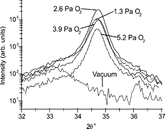 | ||
| Fig. 7 XRD 2θ scans, in the vicinity of the ZnO (0002) reflection, of ZnO:Ga films grown in different background pressures of oxygen, pO2, on sapphire substrates, at Tsub = 723 K. | ||
ZnO film growth on NaCl substrates serve to illustrate the effect that the ablated atom–substrate binding energy, and the benefits of reducing the lattice mismatch, can have on the orientation of PLD grown films.28Fig. 8 (a) shows a transmission electron microscope (TEM) dark field image of a thin film of ZnO grown by 193 nm PLA on an NaCl substrate at Tsub
= 573 K. Selected areas of the substrate surface have been masked with a thin layer of amorphous carbon, prior to film deposition, so that epitaxial growth on NaCl can be compared to growth without any substrate-enforced alignment. Note that each bright spot in the TEM images corresponds to one crystal grain diffracting strongly at the chosen reciprocal lattice vector (g
= 11![[2 with combining macron]](https://www.rsc.org/images/entities/char_0032_0304.gif) 0). Fig. 8(b) shows a selected area electron diffraction (SAED) pattern from the ZnO film deposited on one of the carbon-coated areas. This image shows the ring diffraction pattern of poly-crystalline wurtzite ZnO. The (0002) ring (which would appear between the two easily visible outer rings) is virtually absent, indicative of c-axis orientation. This orientation has been confirmed by XRD measurements. In the absence of any strong interaction between the substrate surface and the ablated atoms, therefore, growth is characterised by the natural growth habit of the crystal system. Contrast this with the SAED pattern from the film deposited on the areas of bare NaCl substrate, shown in Fig. 8(c). This diffraction pattern shows clear spots, with four-fold symmetry, as well as faint rings, demonstrating that significant epitaxial growth is occurring on the substrate, even at this relatively low value of Tsub. In this case the mismatch between the NaCl lattice parameter and the c-axis spacing of ZnO is small. Clearly, in situations where the substrate–ablated atom interaction is sufficiently strong, and the lattice mismatch is small, the orientation of the film can be controlled by the orientation of the substrate.
0). Fig. 8(b) shows a selected area electron diffraction (SAED) pattern from the ZnO film deposited on one of the carbon-coated areas. This image shows the ring diffraction pattern of poly-crystalline wurtzite ZnO. The (0002) ring (which would appear between the two easily visible outer rings) is virtually absent, indicative of c-axis orientation. This orientation has been confirmed by XRD measurements. In the absence of any strong interaction between the substrate surface and the ablated atoms, therefore, growth is characterised by the natural growth habit of the crystal system. Contrast this with the SAED pattern from the film deposited on the areas of bare NaCl substrate, shown in Fig. 8(c). This diffraction pattern shows clear spots, with four-fold symmetry, as well as faint rings, demonstrating that significant epitaxial growth is occurring on the substrate, even at this relatively low value of Tsub. In this case the mismatch between the NaCl lattice parameter and the c-axis spacing of ZnO is small. Clearly, in situations where the substrate–ablated atom interaction is sufficiently strong, and the lattice mismatch is small, the orientation of the film can be controlled by the orientation of the substrate.
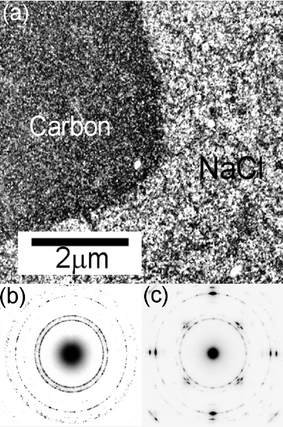 | ||
| Fig. 8 (a) TEM dark field image of a thin film of ZnO grown onto a NaCl substrate at Tsub = 573 K. Selected areas of this substrate surface have been masked with a thin layer of amorphous carbon, prior to ZnO film deposition, thus allowing investigation of epitaxial growth on NaCl. (b) and (c) show SAED patterns from ZnO deposited on areas pre-coated with a carbon film, and on the bare NaCl substrate, respectively. | ||
We now return to consider consequences of the fact that the substrate is only exposed to ablated flux for about 1% of the time in a typical 10 Hz PLD experiment. Such a duty cycle is far from ideal. Recall that material removal rates from the target are typically ∼1015 atoms pulse−1 (i.e. ∼1016 atoms s−1 for a 10 Hz PLA process). Even allowing for the directionality of the ablation plume, this will generally translate into <1014 atoms s−1 incident on a 1 cm2 substrate mounted ∼5 cm from the target. It is easy to calculate that this is a comparable collision rate to that which a 1 cm2 substrate will experience in a constant background pressure of ∼10−6 Torr. Notwithstanding the fact that many of these colliding molecules will have less than unit sticking probability, it follows that film contamination by products from the ambient gas environment is a real possibility, and that film purity will be encouraged by higher laser repetition rates and low base pressures.
193 nm PLA of graphite, in vacuum, yields thin films of hydrogen-free DLC that are adherent and locally nano-smooth. As with the ZnO films discussed above, the quality and crystallinity of DLC films deposited by PLA of graphite is inherently dependent on the growth conditions. Deposition in vacuum at room temperature yields DLC films in which the percentage of sp3 hybridised carbon is dependent on the kinetic energy of the impinging species. Cyclotron experiments29 suggest that particles with kinetic energies in the range 100–200 eV result in films with the highest sp3 fraction. The sp3 % can be reduced in a number of ways. For example, raising Tsub above ∼473 K increases the relaxation and hence the graphitisation of the film. Alternatively, introducing a nitrogen background pressure has been shown to enhance the growth of more fullerene-like graphitic phases.30 Conversely, introducing a background pressure of oxygen,31 or hydrogen32 (Tsub ∼773 K), has been reported to induce the growth of sp3 C–C diamond phase by reactive etching of the sp2 fraction in the deposited film. The quality of the deposited DLC films can easily be assessed via non-destructive laser Raman spectroscopy. At visible excitation wavelengths, the contribution from the sp2 sites overshadows that from the sp3 sites and so is most often used to determine changes in structure rather than bonding contributions. Shorter excitation wavelengths (e.g. 244 nm) are necessary to examine the sp3 sites.
The final images in Fig. 6 also demonstrated particulate production in the PLA of graphite and, as Fig. 9(a) shows, some of these will inevitably end up in the deposited film. Particulates appear to be an inevitable feature of films grown by PLD; their contribution can be minimised but rarely completely eliminated. This particular film was grown by PLA of graphite in a background pressure of 10 mTorr of N2 on a Si substrate at Tsub ∼673 K. Fig. 9(b) shows a close up of one of the particulates on this DLC film. It appears to show evidence of partial melting. Confining the expanding plume within a background gas can encourage particulate formation. Such a strategy has been employed deliberately, to produce nano-sized clusters2 and carbon nanotubes.33 In general, however, particulates in the deposited film are detrimental to the ultimate film properties, and a number of strategies for reducing the particulate density have been advanced. As we have seen, particulates can be created during the PLA process by (i) exfoliation, (ii) stress-induced material breakdown and (iii) explosive boiling. Various workers34 have demonstrated the way in which use of a molten (i.e. liquid) target can greatly reduce particulate formation by exfoliation though this strategy, of course, will generally be restricted to targets with low Tm. Explosive boiling is an important particulate ejection mechanism in most nanosecond PLD experiments. Operating at reduced laser fluence (i.e. below the threshold level for explosive boiling) is thus one option for reducing particulate formation. From the efficiency viewpoint, it is obviously preferable to lower F by enlarging the irradiated area rather than reducing the laser pulse energy, so as to keep the ablation rate as high as possible. Reducing the pulse duration might appear to be another strategy for achieving the same result, since irradiation with a fsec laser pulse favours electronic excitation. Such suggestions are not supported by recent experimental studies of fsec laser ablation of graphite, however.23
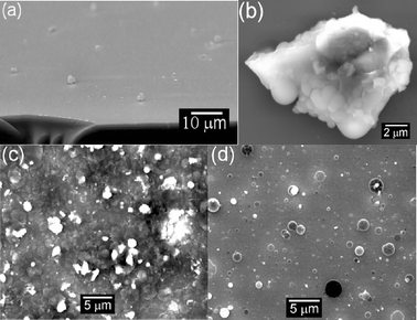 | ||
| Fig. 9 SEM images illustrating particulate inclusion in films grown by 193 nm PLD, in vacuum. (a) Shows a cross-sectional view through a DLC film (10 mTorr N2 background pressure, Tsub ≈ 673 K), while (b) shows a close up of a graphite particulate which shows evidence of partial melting. (c) and (d) show LiF films deposited on Si substrates, with the substrate surface mounted at, respectively, 90° and ∼ 25° to the target surface normal. | ||
Several other strategies for particulate reduction have been demonstrated, though these usually require some redesign of the deposition chamber. One involves the introduction of one or more appropriately synchronised mechanical velocity filters designed so as to transmit fast moving atoms and ions but to block the much more slowly moving particulates.35 Another involves deliberately mounting the substrate so that the surface to be coated is at an acute angle to the plume propagation axis, x. To illustrate the potential of this particular approach, Figs. 9(c) and 9(d) show SEM images of LiF thin films grown by PLD using nanosecond duration 193 nm laser pulses with the Si substrate surface mounted at, respectively, 90° and ∼25° to x; clearly, this strategy can reduce particulate incorporation in the resulting films.36 These images also illustrate that, in the case of UV-PLA of LiF, the particulates leave the target and complete their flight to the substrate as molten droplets, which resolidify after impacting on the substrate. A third strategy involves a combination of an off-axis substrate plus a magnetic field.37 With this method one can arrange that charged particles in the plume are deflected onto the substrate positioned off the surface normal; neutrals (including heavy particulates) are not deflected by the magnetic field and thus do not contribute to the film growth. Use of another laser pulse, propagating parallel to (and close above) the front face of the target and timed so as to intercept the primary ablation plume – and thereby vaporise and/or photodissociate the particulates in the plume – can also lead to dramatic reductions in particulate density.38,39
Conclusions and future prospects
This article has focused on aspects of the fundamental chemical physics of PLA and PLD processes and deposition, and has attempted to track the evolution of material from the target through to the deposited film. Thus we have tried to provide brief overviews of the initial laser–target interactions that cause solid material to enter the gas phase, of the processing and propagation of material in the ablation plume, and of the factors involved in the eventual accommodation of gas phase species onto and into the growing film. The PLA technique is well-established, finding use in applications ranging from MALDI, through many areas of material patterning, to materials analysis by techniques like laser induced breakdown spectroscopy (LIBS).40 The discovery and application of novel materials, and the incorporation of such materials into solid-state devices that may have applications in areas as diverse as biophysics, optoelectronics and nanotechnology, represents a continuing challenge for the solid-state chemical physics community. It has been argued3 that, if one were to list the attributes required for any ‘ideal’ method for depositing thin films of a broad variety of materials, PLD would likely emerge as one of the front-runners amongst the techniques currently available. Congruent transfer from the bulk target into the film is possible (though may require the use of a low pressure of an appropriate background gas). The kinetic energies of ablated particles are typically high enough to promote surface diffusion, but not so high as to induce bulk damage. Ablated species are often activated (as ions, or as electronically excited neutrals), which can aid associative chemistry on the growing film surface. Almost all materials can be ablated, so one could argue that the range of films and multi-layer structures that can be grown in this way is limited only by the ingenuity of the PLD practitioners and the possible applications that can be envisaged. That said, the inclusion of undesirable particulates in films grown by PLD remains an issue, which can be reduced but rarely, as yet, completely eliminated. Clearly, further work is required in this area, in controlling impurity levels within films grown by such methods, and in developing routes to scaling-up and automating the PLD process.Acknowledgements
The authors are grateful to the EPSRC for generous financial support in the form of equipment grants, a Senior Research Fellowship (MNRA), post-doctoral funding (SJH, via the DTI LINK OSDA programme AEROFED) and studentships (FC, GMF). We are also most grateful to Drs N. A. Fox, R. Vincent and Professor D. Cherns for their encouragement of our recent work in this area, and to K. N. Rosser, A. Cheesman, C. J. Rennick and Dr R. J. Lade for their many and varied contributions to this research programme.References
- For a historical overview of the development of PLD see: J. T. Cheung, in Pulsed Laser Deposition of Thin Films, eds. D. B. Chrisey and G. K. Hubler, John Wiley and Sons, New York, Chap. 1, 1994 Search PubMed.
- D. H. Lowdnes, D. B. Geohegan, A. A. Puretzky, D. P. Norton and C. M. Rouleau, Science, 1996, 273, 898 CAS.
- P. R. Willmott and J. R. Huber, Rev. Mod. Phys., 2000, 72, 315 CrossRef CAS.
- I. G. Pallikaris and D. S. Siganos, J. Refractive and Corneal Surgery, 1994, 10, 498 Search PubMed.
- V. Tornari, V. Zafiropulos, A. Bonarou, N. A. Vainos and C. Fotakis, Optics Lasers Eng., 2000, 34, 309 Search PubMed.
- S. Georgiou and F. Hillenkamp editors, Chem. Rev., 2003, 103(2) Search PubMed.
- A. Giardini, V. Marotta, A. Morone, S. Orlando and G. P. Parisi, Appl. Surf. Sci., 2002, 197, 338 CrossRef.
- R. Kelly and A. Miotello, in Pulsed Laser Deposition of Thin Films eds. D. B. Chrisey and G. K. Hubler, John Wiley and Sons, New York, Chap. 3, 1994 Search PubMed.
- W. Hoheisel, K. Jungmann, M. Vollmer, R. Weidenauer and F. Träger, Phys. Rev. Lett., 1988, 60, 1649 CrossRef CAS.
- I. Lee, J. E. Parks, T. A. Callcott and E. T. Arakawa, Phys. Rev. B., 1989, 39, 8012 CrossRef CAS.
- D. J. Krajnovich, J. Chem. Phys., 1995, 102, 726 CrossRef CAS.
- J. S. Gold, W. A. Bassett, M. S. Weathers and J. M. Bird, Science, 1984, 225, 921 CAS.
- J. Steinbeck, G. Braunstein, M. S. Dresselhaus, T. Venkatesan and D. C. Jacobson, J. Appl. Phys., 1985, 58, 4374 CrossRef CAS.
- R. J. Lade, F. Claeyssens, K. N. Rosser and M. N. R. Ashfold, Appl. Phys. A., 1999, 69, S935 CrossRef CAS.
- L. Balasz, R. Gijbels and A. Vertes, Anal. Chem., 1991, 63, 314 CrossRef.
- A. Miotello and R. Kelly, Appl. Phys. A, 1999, 69, S67 CrossRef CAS and references therein.
- A. A. Voevodin and M. S. Donley, Surf. Coat. Technol., 1996, 82, 199 CrossRef CAS.
- F. Claeyssens, A. Cheesman, S. J. Henley and M. N. R. Ashfold, J. Appl. Phys., 2002, 92, 6886 CrossRef CAS and references therein.
- D. J. Krajnovich, J. E. Vazquez and R. J. Savoy, Science, 1993, 259, 1590 CAS.
- See, for example : S. R. Foltyn, in Pulsed Laser Deposition of Thin Films, eds. D. B. Chrisey and G. K. Hubler, John Wiley and Sons, New York, Chap. 4, 1994 Search PubMed and references therein.
- F. Claeyssens, R. J. Lade, K. N. Rosser and M. N. R. Ashfold, J. Appl. Phys., 2001, 89, 697 CrossRef CAS.
- D. B. Geohegan, in Pulsed Laser Deposition of Thin Films, eds. D. B. Chrisey and G. K. Hubler, John Wiley and Sons, New York, Chap. 5, 1994 Search PubMed and references therein.
- F. Claeyssens, M. N. R. Ashfold, E. Sofoulakis, C. G. Ristoscu, D. Anglos and C. Fotakis, J. Appl. Phys., 2002, 91, 6162 CrossRef CAS.
- K. L. Saenger, in Pulsed Laser Deposition of Thin Films, eds. D. B. Chrisey and G. K. Hubler, John Wiley and Sons, New York, Chap. 7, 1994 Search PubMed.
- R. P. van Ingen, J. Appl. Phys., 1996, 79, 467 CrossRef CAS.
- D. H. A. Blank, G. Koster, G. Rijnders, E. van Setten, P. Slycke and H. Rogalla, Appl. Phys. A, 1999, 69, S17 CrossRef CAS.
- J. S. Horwitz and J. A. Sprague, in Pulsed Laser Deposition of Thin Films, D. B. Chrisey and G. K. Hubler, John Wiley and Sons, New York, Chap. 8, 1994 Search PubMed.
- S. J. Henley, M. N. R. Ashfold and D. Cherns, Thin Solid Films, 2002, 422, 69 CrossRef CAS.
- S. Prawer, K. W. Nugent, Y. Lifshitz, G. D. Lempert, E. Grossman, J. Kulik, I. Avigal and R. Kalish, Diamond Relat. Mater., 1996, 5, 433 CrossRef CAS.
- See, for example : A. A. Voevodin and J. S. Zabinski, in Amorphous Carbon: State of the Art, eds. S. R. P. Silva, J. Robertson, W. I. Milne and G. A. J. Amaratunga, 237–251, World Scientific, Singapore, 1998 Search PubMed and references therein.
- M. Yoshimoto, K. Yoshida, H. Maruta, Y. Hishitani, H. Koinuma, S. Nishio, M. Kakihana and T. Tachibana, Nature, 1999, 399, 340 CrossRef CAS.
- M. C. Polo, J. Cifre, G. Sánchez, R. Aguiar, M. Varela and J. Esteve, Appl. Phys. Lett., 1995, 67, 485 CrossRef CAS.
- A. A. Puretzky, D. B. Geohegan, X. Fan and S. J. Pennycook, Appl. Phys. Lett., 2000, 76, 182 CrossRef CAS.
- See, for example : P. R. Willmott and F. Antoni, Appl. Phys. Lett., 1998, 73, 1394 Search PubMed and references therein.
- A. Anders, Surf. Coat. Technol., 1999, 121, 319 CrossRef.
- S. J. Henley, M. N. R. Ashfold and S. R. J. Pearce, Appl. Surf. Sci., 2003, 217, 68 CrossRef CAS.
- G. Radhakrishnan and P. M. Adams, Appl. Phys. A, 1999, 69, S33 CrossRef CAS.
- E. György, I. N. Mihailescu, M. Kompitas and A. Giannoudakos, Appl. Surf. Sci., 2002, 195, 270 CrossRef CAS.
- H. Chiba, K. Murakami, O. Eryu, K. Shihoyama, T. Mochizuki and K. Masuda, Jpn. J. Appl. Phys., 1991, 30(4B), L732 CAS.
- D. A. Rusak, B. C. Castle, B. W. Smith and J. D. Winefordner, Crit. Rev. Anal. Chem., 1997, 27, 257 Search PubMed.
| This journal is © The Royal Society of Chemistry 2004 |