Frequency-dependent electrical detection of protein binding events
Tami L.
Lasseter
,
Wei
Cai
and
Robert J.
Hamers
*
Department of Chemistry, University of Wisconsin-Madison, 1101 University Avenue, Madison, WI 53706, USA. E-mail: rjhamers@wisc.edu; Tel: 608-262-6371
First published on 2nd December 2003
Abstract
Frequency-dependent electrochemical impedance spectroscopy has been used to characterize the changes in electrical response that accompany specific binding of a protein to its substrate, using the biotin–avidin system as a model. Our results show that avidin, at concentrations in the nanomolar range, can be detected electrically in a completely label-free manner under conditions of zero average current flow and without the use of any auxiliary redox agents. Impedance measurements performed on biotin-modified surfaces of gold, glassy carbon, and silicon were obtained over a wide frequency range, from 5 mHz to 1 MHz. On each biotin-modified surface, binding of avidin is most easily detected at low frequencies, <1 Hz. Electrical circuit modeling of the interface was used to relate the frequency-dependent electrical response to the physical structure of the interface before and after avidin binding. Electrical measurements were correlated with measurements of protein binding using fluorescently labeled avidin.
Introduction
While most high-throughput biosensors rely on optical methods such as fluorescence or surface-plasmon resonance to detect biological binding events,1–7 there is great interest in biosensors that involve direct electrical signal transduction. The use of surfaces modified with specific biomolecules as the basis for biological sensing is particularly attractive because sensors of this type could be more easily integrated into very high-density arrays, interfaced to microprocessors, and directly linked to electrical signal-processing methods for detecting biological molecules in real-time.8–11 Understanding the electrical response of surfaces with attached biomolecules is complicated because the overall electrical response contains contributions from the aqueous solutions, the biological layers, and the silicon or other materials that serves as a mechanical and electrical support.Previous studies of electrical detection of biomolecules have focused primarily on changes in DC conductivity that accompany biological binding processes, especially DNA hybridization. These studies have shown that the charge on the DNA molecule, for example, can inhibit diffusion of redox agents to the electrode surface, thereby modifying the resistance across the interface.10,12–16 While DC measurements provide a measurement of overall conductivity, measurements of AC electrical properties can provide a wealth of information about biologically-modified interfaces because the physical and chemical structure at the interface are reflected in the amplitude and phase of the electric current. Perhaps most importantly, a great deal of insight into the mechanism of the analytical signal transduction can be obtained from measurements of electrical properties as a function of frequency. The frequency-dependent properties of surfaces modified with biological molecules can be characterized using techniques such as cyclic voltammetry and electrochemical impedance spectroscopy (EIS).17–20
The previous studies have pointed out two important limitations to the present use of electrical detection for biological systems. First, most electrical detection systems have used redox agents to facilitate electron transfer and have used applied potentials of up to several volts in order force a net current through the biomolecules. However because potentials of even <0.5 V and currents of less than ∼100 µA cm−2 are known to alter the hybridization of DNA21,22 and are likely to modify protein binding, electrical measurements that involve net current flow may be unintentionally modifying the system they are intended to measure. Measurements of delicate biological systems benefit from measurements at lower potentials and low currents. Second, because biomolecules have many different sites that can interact with a surface, understanding the electrical response requires having well-defined, highly reproducible surface chemistry to achieve interfaces with known physical and chemical structure. Most previous EIS studies of biological binding have used multilayer films or other complex structures,17,23 that have made it difficult to achieve a fundamental understanding of the electrical signal transduction process, particularly in the case of proteins.
Here, we use the biotin–avidin system as a model to investigate the intrinsic electrochemical response induced by protein binding. By using very well-defined, covalent chemistry to link the biomolecules to the surfaces, we are able to prepare very reproducible, biotin-modified surfaces of gold, silicon, and glassy carbon. Impedance spectroscopy measurements show that the binding of avidin to a single monolayer of surface-tethered biotin molecules can easily be detected in the nanomolar concentration range even in the absence of any auxiliary redox agents, provided that the measurements are performed in specific frequency ranges. By characterizing the frequency response and how it changes in response to biotin–avidin binding and then coupling this with electrical circuit modeling, our results are able to provide important new insights into the mechanism of signal transduction and the physical factors that control the analytical sensitivity.
Materials and methods
Impedance measurements
The electrochemical cell used in the impedance measurements is depicted in Fig. 1c and d. The cell contains three electrodes: a reference electrode, a working electrode, and a counter electrode. An Ag/AgCl wire was inserted through the fluid channel of a polydimethylsiloxane (PDMS) gasket and into the chamber for use as the reference electrode. The biotinylated surface (gold, silicon or glassy carbon) was used as the working electrode. A ∼0.5 cm × 0.5 cm piece of platinum foil was used as the counter electrode. The counter and the working electrodes formed the top and bottom seals of the chamber after the cell was stacked and pressed together, with a sample area of 0.030 cm2 exposed to the solution. Impedance spectra were measured using a three-electrode potentiostat (Solartron model 1287) coupled with an impedance analyzer (Solartron model 1260). A 30 mV peak-to-peak AC signal was used during all of the experiments; this value was chosen to provide good signal-to-noise at very high impedances while still being close to the thermal broadening of ∼26 mV expected at room temperature. All spectra reported here were measured at the open circuit potential at the start of each scan.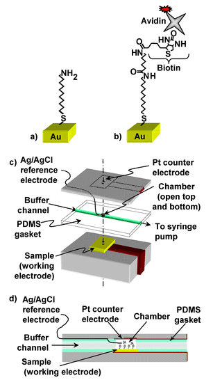 | ||
| Fig. 1 (a) 11-amino undecanethiol hydrochloride (MUAM) adds to a clean gold surface, yielding an amine-terminated surface. (b) A biotin linker, Sulfo-Succinimidyl-6′-(biotinamido)-6-hexamido hexanoate, adds to the amine-terminated surface, yielding a biotinylated surface. Finally, fluorescently labeled avidin binds to the biotinylated surface. (c) Diagram of the fluid cell used for the impedance measurements. (d) A side view of the cell. | ||
Surface modification
Gold surfaces (gold foil, Alfa Aesar) were modified with biotin as outlined in Fig. 1a and b.7 The gold surfaces were first cleaned by exposure to UV light (1.0 A, UV Products) followed by extensive rinsing in deionized water and absolute ethanol. The surfaces were immersed in a solution of 1 mM MUAM solution (11-aminoundecanethiol hydrochloride, Dojindo) in absolute ethanol for 16 h at room temperature in the dark. This step yields an amine-terminated surface that is then reacted with a 1 mM solution of an NHS ester of biotin (sulfo-succinimidyl-6′-(biotinamido)-6-hexamido hexanoate, Pierce Endogen) in 0.1 M triethanolamine buffer, pH 7.0, for 30 min at room temperature. The samples were then rinsed with water to remove excess non-bound NHS ester biotin linker. Gold foil samples functionalized in this way were immediately mounted into a fluid cell for impedance measurements as shown in Fig. 1c and d. N-type (111) silicon surfaces (0.005 Ωcm resistivity) were cleaned, etched, and amine-terminated as described previously.24 Glassy carbon surfaces (Type 2 glassy carbon, Alfa Aesar) were hydrogen terminated in a hydrogen plasma chamber and amine-terminated by exposing the hydrogen terminated surface to trifluoroacetamide-protected 10-aminodec-1-ene under UV light.25 Both the silicon and glassy carbon amine-terminated surfaces were then biotinylated using the same NHS ester of biotin as described above.Buffers
Two different types of buffers were used in these experiments: HEPES buffer (10 mM HEPES, 0.5 M NaCl, pH 8.0) and 2X SSPE buffer (20 mM Na2PO4, 0.3 M NaCl, 2 mM EDTA, pH 7.4, Promega). Triton-X was added to this 2X SSPE buffer, to a final concentration of 0.1 vol.% Triton-X in the 2X buffer. Texas red-labeled avidin (Vector Labs), packaged in HEPES buffer, was used to bind to the biotinylated surfaces. In these experiments, a biotin-functionalized surface was mounted into the electrochemical fluid cell, and buffer was then pumped through the cell at a rate of 0.05 mL min−1 to allow the surface to equilibrate for approximately 1 h. All impedance measurements were taken while buffer was flowing through the cell at a rate of 0.05 mL min−1. Avidin of various concentrations was then injected into the cell. The stock concentration of avidin was 2.0 mg mL−1 (∼30 µM, MW avidin = 68,000 Da), and for these experiments dilutions between 1/5000 and 1/5 from the stock were used. After allowing the avidin to bind to the biotin for 10 min, the surfactant-containing SSPE buffer was drawn through the cell by syringe pump for 5 min at a rate of 0.05 mL min−1 to remove non-bound avidin.Fluorescence imaging
After the impedance measurements were taken, the samples were scanned by a fluorescence scanner (Genomic Systems UC 4 × 4) using a yellow laser source and a 615 nm long pass filter to measure the intensity of the fluorescence due to bound Texas red-labeled avidin. The gain was adjusted as needed to ensure that the signal did not saturate the detector.Results
Avidin binding to biotinylated surfaces was studied using impedance spectroscopy and was confirmed by fluorescence imaging. Electrochemical impedance spectroscopy involves measuring the current that flows in response to a small, sinusoidally-modulated voltage that is applied across the interface. The current has components that are in-phase and out-of-phase with the applied voltage. The electrical properties are typically represented in terms of the impedance,which is described as a complex number Z = Z′+iZ″. In a very simple model, the in-phase (or “real”) component, Z′, arises from resistance, while the out-of-phase (or “imaginary”) component, Z″, is associated with capacitance. Because biomolecular interfaces can have a complicated structure, the impedance represents a combined electrical response of the underlying gold, the molecular interface, and the buffer solution. However, each of these physical structures has its own unique electrical properties. By measuring Z′ and Z″ as a function of frequency, it is possible to separate many of these contributions and thereby optimize sensitivity to processes such as biomolecular binding.

We measured the impedance changes upon exposure to different buffers as background measurements. Fig. 2a and b show the changes in Z′ and Z″ as a function of the applied frequency; the traces are labeled in the order with which the experimental measurements were performed. These same data are presented in the alternative form of a Nyquist plot, as in Fig. 2c. The logarithmic impedance plots (Fig. 2a and b) show the behavior over the entire frequency range, while the linear Nyquist plot (Fig. 2c) more clearly emphasizes the impedance changes at low frequency, where the experiments discussed below show that best sensitivity to the presence of avidin. The impedance of the two different buffers used (SSPE and HEPES) was measured as a function of frequency between 5 mHz and 1 MHz The two traces for HEPES (orange lines, labeled “HEPES bkg”) are completely overlapping in Fig. 2a and b, while on the linear scale in Fig. 2c they can be distinguished upon very close examination. The two traces in SSPE (teal lines, labeled “SSPE bkg”) are also completely overlapping, but are distinct from those of the HEPES buffer. These background measurements show that the impedance is very stable and reproducible over the time scale of the measurements involved (20 min per frequency spectrum).
 | ||
| Fig. 2 The in-phase part (a) and the out-of-phase part (b) of the impedance versus frequency after increasing concentrations of avidin were allowed to bind to the surface. (c) Nyquist plot of the impedance measured after increasing concentrations of avidin were allowed to bind to the surface. (d) Plot of the magnitude of the impedance and fluorescence intensity versus concentration. The impedance change was calculated by subtracting the |Z| value at 0.1 Hz of HEPES background from the 0.1 Hz |Z| values of the various concentrations. Fluorescence data was obtained for comparison with the impedance data. A fluorescence image at the 0.3 µM concentration is shown in the inset. | ||
After ensuring that the sweeps were stable and reproducible, the sample was exposed to varying concentrations of avidin. Because the equilibrium binding constant of avidin to biotin is very large (∼1015 M), binding is expected to be irreversible and limited only by the adsorption kinetics. Under these conditions the density of surface-bound avidin is expected to depend on the total exposure, defined as the solution avidin concentration multiplied by the time of exposure to the biotin-modified surface. The experiments reported here used a fixed exposure time of 10 min. First, a 1/5000 dilution from the stock avidin was injected (0.4 µg mL−1). After allowing 10 min (at 300K) for the avidin to bind, SSPE buffer was drawn through the cell for 5 min at a rate of 0.05 mL min−1. Impedance spectra were then measured in the SSPE buffer and finally in the HEPES buffer, as plotted in Fig. 2a–c. The same experiment—an injection of avidin, a 10 min binding time, a 5 min washing time, and impedance measurements in SSPE and HEPES—was carried out for successively increasing concentrations of avidin, yielding the complete set of traces shown in Fig. 2a–c.
At frequencies less than 1 Hz (Fig. 2a and b) the curves measured after different avidin exposures are distinct, with both Z′ and Z″ of the impedance increasing after exposure to avidin. In this range the impedance appears to be sensitive to the presence of avidin. At intermediate frequencies, between 2 Hz and 20 kHz, all traces are nearly overlapping. At high frequencies, greater than 103 Hz, the curves in HEPES and SSPE buffers diverge and do not depend strongly on avidin concentration, demonstrating that at high frequencies the impedance is sensitive to the composition of the buffer solution; the high-frequency limit corresponds to the ohmic resistance of the solution. Measurements of the open-circuit potential (OCP) also show a shift as avidin is introduced, but this is quite small, shifting only +18 mV over the entire data set from the bare biotin-modified surface to the avidin-saturated surface.
While the logarithmic plot in Fig. 2a and b shows the overall response, the impedance changes in the low-frequency range can be seen more clearly on a linear graph. Fig. 2c shows a Nyquist plot in which the real and imaginary components of the complex impedance at different frequencies are plotted from a locus of points. The impedance increases monotonically as the total exposure to avidin increases. However, after exposure to 1/5 dilution from stock (0.4 mg mL−1), further exposure to 1/10 dilutions (0.2 mg mL−1) produced no further change in the impedance spectrum. The overlap of the traces demonstrates that avidin eventually saturates the surface and the impedance shows no further change.
To verify that the changes in impedance arise from the avidin–biotin binding, control experiments (not shown) were conducted in which biotin-modified surfaces were exposed to avidin that was pre-saturated with biotin, and thus unable to bind to a biotinylated surface. Impedance measurements showed that biotin-saturated avidin produced only a 4.3% change at 10 mHz in the magnitude of the impedance, |Z|, while a 48.7% increase was observed when non-blocked avidin saturated the surface. This data confirms that the impedance changes observed in Fig. 2a–c arise from the specific binding of avidin to biotin and do not arise from other effects such as physisorption or electronic drift.
Since exposure to avidin increases the real and imaginary parts of the impedance, the total impedance,

The impedance changes were corroborated with fluorescence measurements in which various concentrations of avidin were spotted onto a biotinylated gold surface, allowed to bind for 10 min, and then washed for 5 min in the SSPE buffer (Fig. 2d). The impedance data and the fluorescence data both show saturation of the surface when exposed to concentrations of >2 µM of avidin, although the impedance measurements appear to show saturation at a lower total exposure. This difference in exposure needed to saturate the fluorescence intensity and the impedance change remains unclear. A change in impedance could saturate at an anomalously low exposure if avidin binds preferentially at a small number of surface or defect sites that dominate the impedance.26 Alternatively, fluorescence measurements could show saturation only at anomalously high exposures if there is significant quenching due to resonant energy transfer between the fluorescent tag molecules.27,28
To determine whether the ability to detect avidin via electrochemical impedance spectroscopy can be extended to other biotin-modified substrates, we performed similar experiments using silicon and glassy carbon substrates. In each case, the surfaces were amine-terminated,24,25 functionalized with biotin, and then exposed to avidin. The results from these surfaces are shown in Fig. 3. Biotin-modified surfaces of silicon and of glassy carbon both show an increase in the magnitude of both the in-phase (Z′) and the out-of-phase (Z″) components of the impedance after binding, similar to what was observed with gold. These results are important for two reasons: first, they establish the generality of impedance spectroscopy for use as a direct electronic detection technique to monitor protein binding. Second, the similarity in behavior on all three surfaces studied suggests that the impedance changes are not strongly dependent on the substrate, but are due to changes in the molecular layer (the biotin and its linker) arising from the binding of avidin to the biotin-modified surfaces.
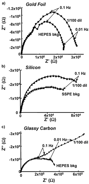 | ||
| Fig. 3 Nyquist (Z″ vs. Z′) plots on three different surfaces, gold foil (a), silicon (b), and glassy carbon (c) are shown. | ||
Discussion
An understanding of the physical origin of the observed response can be enhanced using electrical circuit modeling, in which the electrical response of the physical interface is modeled using various discrete electrical circuit elements. The interface can be divided into three physical regions: (1) the electrolyte, (2) the molecular layer, and (3) the substrate (gold, silicon, or glassy carbon). Previous studies of chemically-modified surfaces have found that simple series and parallel combinations of resistors and capacitors are usually insufficient to represent the electrical response, necessitating the use of more generalized electronic elements, such as constant phase elements (CPEs) and Warburg elements.17,19,23,29–33We have explored fitting the impedance data with a number of commonly used circuit models. The model that provides the best fit to the data is shown in Fig. 4b. This model represents the physical structure of the interface (Fig. 4a) in terms of three layers, each with its own unique electrical properties. The “inner layer” corresponds to the surface-linked MUAM molecules, specifically adsorbed ions at the surface, and a more diffuse layer of counter ions that are interspersed among the MUAM molecules. The thickness of the diffuse layer can be estimated from Gouy–Chapman–Stern theory and is approximately 1 nm under the conditions used in our experiments.34 Because this thickness is close to that of the MUAM layer (∼1.6 nm), the frequency dependence of this layer is complicated and is represented by a parallel combination of a resistor and a constant phase element (CPE). The CPE has an impedance defined by

 | ||
| Fig. 4 (a) Physical representation of the biotinylated surface, showing the total molecular layer, the inner layer (about 10 Å in thickness), and the outer layer. (b) The equivalent circuit model used to fit these data with the labeled brackets showing the likely correlation between electrical components used to model the interface and the physical representation of these layers. The phase angle (θ) versus frequency for the data set from a 1/10 dil SSPE is plotted in (c) and the magnitude (|Z|) versus frequency is shown in (d). The values of the circuit elements obtained from the equivalent circuit model are plotted versus frequency in (d). The bar scale at the top of (c) and (d) identify which circuit element dominates the total impedance in each frequency range. | ||
While no equivalent model can be guaranteed to be unique, the validity of the model in Fig. 4b is supported by the fact that it fits the data extremely well over the entire frequency range (more than 8 decades). Table 1 shows selected values of the circuit elements obtained by fitting the experimental data in Fig. 2 to the circuit model shown in Fig. 4b. The role of the electrolyte ohmic resistance Rbulk can be easily separated from the other contributing circuit elements by changing buffers and noting the changes at high frequency. However, the similarities of the fit parameters associated with the inner and outer molecular layers makes definitive assignments of these layers to their specific electrical components difficult, and our experiments show that binding of avidin to biotin changes both the inner and outer molecular layers. This result is not surprising, since the length scales associated with the diffuse layers and the molecular layer are comparable to one another and the physical structure of the interface is not atomically sharp. A detailed discussion of the circuit modeling of these layers will be presented in a future publication.35
| OCP, V | R bulk/Ω | R inner/MΩ | CPEinner:Tinner | CPEinner:ϕinner | Router/MΩ | CPEouter:Touter | CPEouter:ϕouter | |
|---|---|---|---|---|---|---|---|---|
| SSPE bkg | −0.236 | 139 ± 0.6 | 0.558 ± 0.027 | (1.36 ± 0.01) × 10−7 | 0.939 ± 0.006 | 2.06 ± 0.04 | (494 ± 15) × 10−7 | 0.897 ± 0.011 |
| 1/5000 dil avidin in SSPE | −0.232 | 135 ± 0.7 | 0.534 ± 0.027 | (1.31 ± 0.02) × 10−7 | 0.940 ± 0.006 | 2.32 ± 0.04 | (476 ± 14) × 10−7 | 0.900 ± 0.012 |
| 1/5 dil avidin in SSPE | −0.221 | 134 ± 0.6 | 0.725 ± 0.046 | (1.35 ± 0.02) × 10−7 | 0.937 ± 0.007 | 2.75 ± 0.07 | (435 ± 17) × 10−7 | 0.913 ± 0.016 |
From the standpoint of biological sensing, the most important result of the circuit modeling is that it provides a way to understand the frequency dependence of the electrical response resulting from biotin–avidin binding. Fig. 4c and d show an analysis of the impedance data and also indicate the electrical components that control the total impedance in each frequency range. In this plot, the data are presented in terms of the magnitude and phase angle of the impedance data. At frequencies below ∼0.5 Hz, the total impedance is dominated by Router and the impedance of CPEouter. At intermediate frequencies (between 2 Hz and 20 kHz) the impedance is dominated primarily by the inner constant phase element CPEinner, which provides no significant sensitivity to avidin binding. At the highest frequencies (greater than 20 kHz), the impedance is dominated by the bulk solution resistance, Rbulk which is dependent upon the ionic strength of the buffer that is used, but does not change when avidin binds to the surface.
Detailed analysis of the data shows that when avidin is added to the system, the principal changes are in the values of the resistors in the molecular layer, Rinner and Router, along with the parameters of CPEouter. The avidin-induced changes can be sensed electrically at low frequencies because in this frequency range the overall impedance is dominated by the resistance of the molecular layer. At the highest frequencies, the circuit model predicts that the overall impedance of the system is controlled by the bulk solution resistance, Rbulk. The validity of this conclusion is clearly demonstrated by the fact that in Fig. 2a and b, the impedance curves at >20 kHz reflect primarily the composition of the HEPES and SSPE buffer solutions and are not affected by the presence of avidin.
A comparison of the impedance spectra on each of the different surfaces (gold, glassy carbon, and silicon) shows that in each case the binding of avidin to the biotin-modified surfaces produces an increase in Router and Rinner. Since attachment of biotin to these surfaces involves very similar chemistry, the chemical structure of the molecular layer is expected to be nearly the same. However, the physical structure of the molecular layer depends on the smoothness and porosity of the underlying surface, which is expected to be different for gold, silicon and glassy carbon. Wet-etched Si(111) surfaces are known to be very smooth,36 and at the high doping level used in our studies it is expected to be nearly metallic. The gold foil used in our impedance studies is rough on a molecular level, while the glassy carbon is somewhat porous due to the surface structure described as having tangled ribbons of graphite crystals.37 The effects of these different physical interface structures are evidenced by the differences in the shapes of the Nyquist plots in Fig. 3, and by different values of the circuit elements used to model the data. In the case of glassy carbon, the long tail observed (Fig. 3c) at low frequencies is suggestive of a diffusion-controlled reaction, which is commonly fit using a Warburg element.19,23 Yet, fitting the data with a Warburg Element instead of the CPE decreased the quality of the fit, suggesting that the impedance is not entirely diffusion controlled. On each of the three surfaces, an increase in the resistance of Rinner and Router is observed upon avidin binding. Thus, our results suggest that the increase in impedance associated with binding of avidin to biotin-modified surfaces is a general phenomenon that arises from the biomolecular layers.
While there are many possible methods for detecting biological binding events, EIS has the ability to detect biological binding events without the use of labels or additives of any kind and directly converts biological information into electrical information. Most previous electrochemical studies of surfaces modified with biomolecules have added a redox couple to act as an intermediate for electron transfer during impedance measurements.38,39 In fact, elaborate methods have been used to bind a redox agent to a biomolecule, such as a ferrocene–avidin conjugate.40 However, redox-based detection methods ultimately may find limited utility because the molecular layers used to attach the biomolecules to the surface may prevent the electron transfer, while the redox agents can decrease the stability of the surface.41 Furthermore, applying significant voltages in order to force a steady current through the biological system brings with it the unintended possibility of inducing chemical or physical modifications that may alter binding or otherwise reduce the stability of the interface.10,21,42 In contrast, the measurements that we report here were obtained at the open circuit potential, where the net current flow is zero. Since the sinusoidal modulation voltage of 30 mV involves an electrical energy that is comparable with thermal energies (kBT/e = 26 mV at 300K) and is small compared with typical bond strengths of 2–5 eV, the use of EIS at the open circuit potential is an extremely gentle measurement technique. While demonstrated here for the binding of avidin to biotinylated surfaces, the combination of specific molecular recognition (via chemical modification of the surface) with electrical detection provides a very sensitive, label-free way of detecting a wide range of protein binding events.
Conclusions
Our results show that impedance spectroscopy can be used as a basis for high-sensitivity detection of proteins. Characterizing and analyzing the electrical response over a wide range of frequencies provides information that can be used to optimize sensor response and to improve the ability to distinguish specific biological binding events from other physical and/or chemical processes at the interface, such as changes in buffer composition or sensor degradation. The overall similarity in the frequency-dependent response on gold, glassy carbon, and silicon surfaces indicates that similar physical processes are controlling the overall electrical response, albeit with some differences arising from differences in microscopic morphology. Although most previous studies have added auxiliary redox agents to facilitate electron transfer, our results show that these redox agents are not necessary when using AC methods instead of DC methods and operating at the open circuit potential. Since the measurement process does not contribute any additional electrical potential and the AC voltage is very small, this set of conditions represents a very non-intrusive way for characterizing the intrinsic electrical properties of biomolecular interfaces that should be applicable to much weaker protein binding events as well as a wide range of other biological systems such as antibody-antigen binding, enzymatic reactions, and cellular dynamics.Acknowledgements
The authors gratefully acknowledge Professor Lloyd M. Smith, Professor Daniel van der Weide, Wensha Yang, and John Peck. This work was supported by the Wisconsin Alumni Research Foundation and the National Institutes of Health Grant R01 EB00269. Any opinions, findings, and conclusions or recommendations expressed in this publication are those of the authors and do not necessarily reflect the views of these agencies.References
- S. P. A. Fodor, R. P. Rava, X. H. C. Huang, A. C. Pease, C. P. Holmes and C. L. Adams, Nature, 1993, 364, 555 CrossRef CAS.
- D. I. Stimpson, J. V. Houer, W. T. Hsieh, C. Jou, T. Theriault, R. Gamble and J. D. Baldeschwieler, Proc. Natl. Acad. Sci. USA, 1995, 92, 6379 CAS.
- U. Maskos and E. M. Southern, Nucleic Acids Res., 1993, 21, 2267 CAS.
- A. P. Blanchard, R. J. Kaiser and L. E. Hood, Biosens. Bioelectron., 1996, 11, 687 CrossRef CAS.
- E. Southern, K. Mir and M. Shchepinov, Nat. Genetics, 1999, 21, 5 Search PubMed.
- K. A. Peterlinz, R. M. Georgiadis, T. M. Herne and M. J. Tarlov, J. Am. Chem. Soc., 1997, 119, 3401 CrossRef CAS.
- C. E. Jordan, A. Frutos, G. A. J. Thiel and R. M. Corn, Anal. Chem., 1997, 69, 4939 CrossRef CAS.
- P. Bergveld, IEEE Trans. Biomed. Eng, 1970, 17, 70 CAS.
- E. Souteyrand, J. P. Cloarec, J. R. Martin, C. Wilson, I. Lawrence, S. Mikkelsen and M. F. Lawrence, J. Phys. Chem., B, 1997, 101, 2980 CrossRef CAS.
- X. H. Xu and A. J. Bard, J. Am. Chem. Soc., 1995, 117, 2627 CrossRef CAS.
- M. J. Schöning and A. Poghossian, Analyst, 2002, 127, 1137 RSC.
- D. Hall, R. E. Holmlin and J. K. Barton, Nature, 1996, 382, 731 CrossRef CAS.
- A. B. Steel, T. M. Herne and M. J. Tarlov, Anal. Chem., 1998, 70, 4670 CrossRef CAS.
- A. B. Steel, T. M. Herne and M. J. Tarlov, Bioconjugate Chem., 1999, 10, 419 CrossRef CAS.
- S. O. Kelley, N. M. Jackson, M. G. Hill and J. K. Barton, Angew. Chem. Int. Ed., 1999, 38, 941 CrossRef.
- E. M. Boon, D. M. Ceres, T. G. Drummond, M. G. Hill and J. K. Barton, Nat. Biotechnol., 2000, 18, 1096 CrossRef CAS.
- A. B. Kharitonov, J. Wasserman, E. Katz and I. Willner, J. Phys. Chem., B, 2001, 105, 4205 CrossRef CAS.
- J. P. Cloarec, N. Deligianis, J. R. Martin, I. Lawrence, E. Souteyrand, C. Polychronakos and M. F. Lawrence, Biosens. Bioelectron., 2002, 17, 405 CrossRef CAS.
- Z. Wu, J. Tang, Z. Cheng, X. Yang and E. Wang, Anal. Chem., 2000, 72, 6030 CrossRef CAS.
- M. M. de Ficquelmont-Loizos, H. Takenouti and W. Kante, J. Electroanal. Chem., 1997, 428, 129 CrossRef.
- R. J. Heaton, A. W. Peterson and R. M. Georgiadis, Proc. Natl. Acad. Sci., 2001, 98, 3701 CrossRef CAS.
- R. G. Sosnowski, E. To, F. W. Butler, J. P. O'Connell and M. J. Heller, Proc. Natl. Acad. Sci. USA, 1997, 94, 1119 CrossRef CAS.
- M. M. de Ficquelmont-Loizos, H. Takenouti and W. Kante, J. Electroanal. Chem., 1997, 428, 129 CrossRef.
- T. Strother, W. Cai, X. Zhao, R. J. Hamers and L. M. Smith, J. Am. Chem. Soc., 2000, 122, 1205 CrossRef CAS.
- T. Strother, T. Knockerbocker, J. N. Russell, Jr, J. E. Butler, L. M. Smith and R. J. Hamers, Langmuir, 2002, 18, 968 CrossRef CAS.
- P. Diao, M. Guo and R. Tong, J. Electroanal. Chem., 2001, 495, 98 CrossRef CAS.
- G. H. McGall, A. D. Barone, M. Diggelmann, S. P. A. Fodor, E. Gentalen and N. Ngo, J. Am. Chem. Soc., 1997, 119, 5081 CrossRef CAS.
- T. Förster, Naturwissenschaften, 1947, 6, 166.
- J. Liu and S. Dong, Electrochem. Commun., 2000, 2, 707 CrossRef CAS.
- S. Varma and C. K. Mitra, Electroanalysis, 2002, 14, 1587 CrossRef CAS.
- Z. Wu, B. Wang, Z. Cheng, X. Yang, S. Dong and E. Wang, Biosens. Bioelectron., 2001, 16, 47 CrossRef CAS.
- E. Boubour and R. B. Lennox, Langmuir, 2000, 16, 7464 CrossRef CAS.
- J. Bisquert, G. Garcia-Belmonte, F. Fabregat-Santiago, N. S. Ferriols, P. Bogdanoff and E. C. Pereira, J. Phys. Chem., B, 2000, 104, 2287 CrossRef CAS.
- A. J. Bard and L. R. Faulkner, in Electrochemical Methods: Fundamentals and Applications, John Wiley & Sons Inc., 2nd edn. 2001, pp. 534 Search PubMed.
- T. L. Lasseter, and R. J. Hamers, article in preparation.
- M. A. Hines, Y. J. Chabal, T. D. Harris and A. Harris, J. Chem. Phys., 1994, 101, 8055 CrossRef CAS.
- P. Heiduschka, A. W. Munz and W. Gopel, Electrochim. Acta, 1994, 39, 2207 CrossRef CAS.
- J. Xu, Q. Chen and G. M. Swain, Anal. Chem., 1998, 70, 3146 CrossRef CAS.
- S. Ferro and A. D. Battisti, Electochim. Acta, 2002, 47, 1641 CrossRef CAS.
- C. Padeste, A. Grubelnik and L. Tiefenauer, Biosens. Bioelectron., 2000, 15, 431 CrossRef CAS.
- M. Dijksma, B. A. Boukamp, B. Kamp and W. P. van Bennekom, Langmuir, 2002, 18, 3105 CrossRef CAS.
- W. R. Everett and I. Fritschfaules, Anal. Chim. Acta, 1995, 307, 253 CrossRef CAS.
| This journal is © The Royal Society of Chemistry 2004 |