Measurement of density and chemical concentration using a microfluidic chip
D.
Sparks
*,
R.
Smith
,
M.
Straayer
,
J.
Cripe
,
R.
Schneider
,
A.
Chimbayo
,
S.
Anasari
and
N.
Najafi
Integrated Sensing Systems Inc, 391 Airport Industrial Dr, Ypsilanti, MI 48198, USA. E-mail: dsparks@mems-issys.com; Fax: (734)547-9964; Tel: (734)547-9896 ext 119
First published on 3rd February 2003
Abstract
A new microfluidic product for measuring fluid density, specific gravity and chemical concentration has been developed. At the core of this lab-on-a-chip sensor is a vacuum-sealed resonating silicon microtube. Measurements can be made with under a microliter of sample fluid, which is over 1000× less than is conventionally required. Since the product is MEMS-based the overall system size is a fraction of conventional density meters and it weighs much less than the traditional desk-top, temperature controlled, density meters. The syringe or pipette loaded system includes a dynamic temperature control system that operates between 0 °C and 90 °C with an accuracy of less than 0.01 °C. Density measurement accuracies of 4 to 5 digits have been observed with aqueous solutions. Measurement examples and applications will be discussed.
Introduction
A lab-on-chip device capable of measuring the density or specific gravity of a fluid as well as mass-based chemical concentration of liquid mixtures to very precise levels of accuracy is covered in this paper.A variety of density measurement techniques are currently in use. For solids and slurries, gravimetric, gamma ray, microwave and ultrasonic techniques are employed. For liquids floating bulb hydrometers are used for approximate density measurements (2 digits of accuracy), but for more accurate readings (3–5 digits of accuracy) density is most often measured using a resonating glass or metal tube.
The vibrating tube liquid density meter concept dates back to the 1920s, when the measurement of the audio frequency of fluid filled vibrating columns was first employed by Ruben.1 Between 1965 and 1973, electronically controlled U-shaped oscillating metal and glass tubes and temperature control were applied to the manufacturing density meters.2,3 Density measurement methodology is simple in such a device, the higher the weight of the fluid, the lower the resonant frequency of the filled tube.
Applications for density sensors exist in the pharmaceutical, biomedical, nuclear, perfume, petroleum and beverage industries as well as in distilleries, hematology and urology. The device can be used to measure density, specific gravity, proof, °Brix, °Plato, API gravity and chemical concentrations. The beverage industry uses the meter for determining the sucrose, alcohol and extract percentages. Since distilleries are taxed based on alcohol content, measurement accuracy is of great importance. The petroleum industry employs the device to check fuel grade and water and alcohol percentage. Pharmaceutical companies utilize the device for serum, fermenter and lab checks. Acid concentration is checked with a density meter with respect to batteries, electroplating and industrial processing. Urine typically has a specific gravity range of 1.010 to 1.025. Urologists test the specific gravity of urine to assist in diagnosing diabetes, glucosuria, proteinuria, hypertension, stroke, dehydration, toxic poisoning, renal and heart failure.4 Density meters have also been employed to measure or control perfume processing, blood hematocrit, deuterium percentage and pesticide concentration.
Experimental
Silicon microtube technology
Laboratory micromachined density sensors have been under basic development for several years.5–7 In this paper the first laboratory-grade density meter, made using micromachining technology, will be discussed. The fabrication process uses a combination of plasma and wet etching, photolithography, along with wafer bonding to form the microfluidic chips. The Integrated Sensing Systems Inc. (ISSYS) silicon microtube process technology allows tube channel widths to vary from 10 to over 1000 microns in width, which enables design variation in sample size and sensitivity. Fig. 1 shows a comparative cross-section of a single crystal silicon microtube and a human hair at the same magnification (750×). The density or specific gravity sensor employs a chip-level, vacuum packaged, resonating silicon tube. Fig. 2 shows the size of such a U-shaped microtube chip next to a coin. The configuration shown in Fig. 2 was used to take all data cited in this paper. This particular microtube has a cross-section of 500 μm by 120 μm. The process has been described in detail previously5,7 and involves several micromachined wafer bonding and etch steps to produce the final chip. The silicon tube, shown on the left of Fig. 2, is anodically bonded to glass. This glass wafer contains the metal electrodes and runners used to carry electrical signals. A silicon-capping wafer is bonded to the glass wafer to form the microvacuum chamber. Both a vacuum capped chip and uncapped chip, showing the tube, are presented in Fig. 2. Two half-millimeter diameter holes in the bottom glass chip admit fluid into the U-shaped silicon microtubes. While filled with a fluid, the tube is driven into resonance electrostatically and its motion sensed capacitively using metal electrodes under the tube and accompanying electronic circuits connected to the MEMS (MicroElectroMechanical System) chip via wire bonding. The metal electrodes are formed on the glass wafer and are the same width as the microtubes (500 μm). The resonant frequency of the microtube varies from 11 KHz empty down to 6 KHz when filled with a dense (2 g cm−3) fluid. As an example of frequency change, the frequency of a water filled microtube is 8581 Hz at 23 °C. | ||
| Fig. 1 A cleaved silicon microtube and a human hair (750×). | ||
 | ||
| Fig. 2 Vacuum capped MEMS die (right) and an uncapped density chip (left). The temperature sensor is also located on the glass chip. | ||
A capacitive sensor performs best with small gaps between electrodes. For micromachines, close spacing leads to squeeze film damping during motion.8 For a resonant device, extensive damping results in low Q values (resonator quality factor) or poor signal-to-noise ratio. Vacuum packaging of the microtube is employed to overcome this problem along with a compatible electrical lead transfer design. This has been accomplished using vacuum wafer-to-wafer bonding methods. Wafer-to-wafer bonding has been used reliably for decades to hermetically seal pressure sensors, accelerometer, gyroscopes and other microsystems.9–11Q values in the 5000 to 20000 range have been obtained through wafer bonding with this sensor. This hermetic seal has survived thermal shock, vibration and over 7000 h of accelerated high temperature testing at 95 °C without loss of vacuum. Since it does not plastically deform below 700 °C, single crystal silicon is an excellent material choice for fabricating resonators. Like glass, single crystal silicon is not subject to the cyclic fatigue problems that have been noted in polycrystalline silicon or metal micromachined resonators.12,13 The hollow silicon resonators used in this density meters have sustained billions of cycles without failure.
While close micromachine electrode gaps lead to squeeze film damping, on a positive side they also result in lower bias requirements for electrostatically driven resonators when coupled with excellent vacuum quality. The silicon density meter devices described in this paper requires from 0 to 5 V of DC bias to electrostatically resonate. Because of this low bias requirement charge pumps or other techniques are not needed to boost the incoming system supply voltage, and electrostatic stiction and sensor drift is less likely. Stiction is a problem encountered with micromachined devices, in which a cantilever or diaphragm sticks to an opposing surface.
By utilizing micromachining technology, the sample volume required to take a mass-based binary chemical concentration measurement has been reduced by over 1000 times that required by conventional glass tube sensors. From 1 to 3 ml of fluid is required for the glass tube sensor, while only 1 microliter is recommended for the silicon microtube. The resonating portion of the microtube shown in Fig. 2 actually holds just 600 nanoliters, and this amount can be reduced through a MEMS design shrink if needed.
System design and operation
Useful density and specific gravity measurements require more than just a microchip. A complete system with adjustable temperature, easily used fluid ports and data output (display and RS 232) are required. Density, specific gravity and temperature are displayed. Fig. 3 shows the assembled meter. Fluids are loaded into the meter via a syringe, pipette or pump. The sample fluids wet silicon, glass and stainless steel. After air bubble removal and priming, pump pressures as low as 5–10 psi can be used to supply liquids to the density meter. As in the case of the existing glass resonating density sensors, the tubes must be cleaned of any fluids that could leave behind a coating. If this is not done, the tube coating will affect the baseline resonant frequency requiring recalibration using air and degassed, de-ionized (DI) water. By using a needle tipped syringe the fluid dead space can be minimized for valuable samples. Volatile, multi-component samples can be drawn from a septum-covered vial to preserve the light molecules. Lower sample volume capability is important to the system user when samples are difficult and/or expensive to obtain. Also with a 1 ml sample, one test can be made with the glass tube device, while 10 to 100 could be tested with the microtube device. Multiple data points from the same sample enable the statistical analysis of the sample to both reduce and measure experimental error. Sources of testing error include gas bubbles, inhomogeneous particle distributions, temperature variability and time since the last system calibration. | ||
| Fig. 3 Syringe loading of the temperature controlled, micro density meter. | ||
Since the density of most fluids varies strongly with temperature, precise temperature control is required to produce an accurate meter. Temperature control requires a heating and cooling system, heat sinks and a stable thermal mass. The measurement temperature of the system can be controlled between 0 °C and 90 °C. The microfluidic chip is mounted between two Peltier panels. An on-chip temperature sensor and feedback control enables a temperature stability of ±0.01 °C. Since a micromachined sensor chip is employed, the temperature control system weighs only 1 kg which is much less than traditional (20–28 kg) temperature controlled density meters. The majority of the weight is required for thermal stability. For field testing, weight is one of the most important system specifications when both accuracy and mobility are required. Microsystem technology enables this weight advantage over conventional measurement technologies.
Results
The key results for evaluating an accurate density meter involve temperature control capability, measurement accuracy of known standards and how the system can be used to measure chemical concentrations of multi-component solutions.Through the use of the Peltier panels, on-chip temperature sensors and control circuits, a temperature control of 10 milli-degrees Celsius has been obtained. The time it takes for the sample to achieve this temperature varies with the fluid and its temperature prior to loading in the meter, but is typically under 1 to 2 min.
The density measurement accuracy can be tested with well understood fluids. Deionized water was employed to test the accuracy of the device. Only 1 min of soak time was taken between measurements. The temperature of the meter was set to 15.55 °C and the water sample, at 23 °C, was loaded into the system with a syringe. Twenty measurements were made. The average density reading was 0.999023 g cm−3 with a standard deviation of 0.000028 g cm−3. The reference density value for water at 15.55 °C is 0.999022 g cm−3.14
To illustrate how the system can be used to measure chemical concentration, data were taken for various volume percentages of methanol/water solutions. Fig. 4 shows a plot of methanol concentration versus density at 20 °C. Methanol concentration in water is of importance in fuel cell development. This type of density data is also used by the beverage industries for measuring sucrose and alcohol percentage in aqueous solutions, in the petrochemical industry for mixing and grading fuels, and in a variety of other chemical and pharmaceutical applications for both manufacturing and quality control.
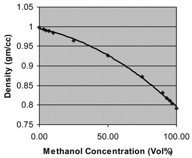 | ||
| Fig. 4 Density measurements versus methanol/water concentration at 20 °C. | ||
Conclusions
A new microfluidic device for measuring fluid density, specific gravity and concentration has been developed. At the core of this sensor is a resonating silicon microtube. Measurements can be made with less than a microliter of sample fluid. Since the product is MEMS-based, the required sample volume and overall system size are a fraction of those of current density meters and its weight is much less than that of a conventional desk-top density meter. The system includes a dynamic temperature control system that operates between 0 °C and 90 °C with an accuracy of better than 0.01 °C. The sensor is capable of better than 4 to 5 digits of accuracy. Applications for this device are found in the pharmaceutical, biomedical, nuclear, perfume, petroleum and beverage industries as well as in distilleries, hematology and urology.References
- S. Ruben, US Patent 1,570,781, 1926.
- W. Banks, US Patent 3,177,705, 1965.
- S. Janssen, US Patent 3,728,893, 1973.
- NIH, Medical Encyclopedia, MedLinePlus, www.nlm.nih.gov/medlineplus/ency, 2002.
- Y. Zhang, S. Tadigadapa and N. Najafi, Transducers’01, The 11th International Conference on Solid-State Sensors and Actuators, Munich, Germany, June 10–14 2001, p. 1460 Search PubMed.
- P. Enoksson, G. Stemme and E. Stemme, Sens. Actuators A, 1995, 46, 327 CrossRef.
- S. Tadigapada, C. Tsai, Y. Zhang and N. Najafi, US Patent 6477,901, 2002.
- J. Starr, Proc. Solid-State Sensors & Actuator Workshop, 1990, 44 Search PubMed.
- W. Ko, J. Suminto and G. Yeh, Micromachining and Micropackaging of Transducers, Elsevier Science Publishers, Amsterdam, 1985, p. 41 Search PubMed.
- D. Sparks, D. Slaughter, R. Beni, L. Jordan, M. Chia, D. Rich, J. Johnson and T. Vas, Sens. Mater., 1999, 11, 197 Search PubMed.
- D. Sparks, G. Queen, R. Weston, G. Woodward, M. Putty, L. Jordan, S. Zarabadi and K. Jayakar, J. Micromech. Microeng., 2001, 11, 630 CrossRef CAS.
- J. Bagdahn and W. Sharpe, MEMS 2002, IEEE International Conference, Las Vegas, USA, 2002, p. 447 Search PubMed.
- D. Sparks, M. Chia and G. Jiang, Sens. Actuators A, 2001, 95, 61 CrossRef.
- H. Bettin and F. Spieweck, Die Dichte des Wassers als Funktion der Temperatur nach Einfurung der Internationalen Temperaturskala van 1990, PTB-Mitt., 1990, 100, 195 Search PubMed.
| This journal is © The Royal Society of Chemistry 2003 |