3,4-Ethylenedioxy-substituted bithiophene-alt-thiophene-S,S-dioxide regular copolymers. Synthesis and conductive, magnetic and luminescence properties.
Anna
Berlin
*a,
Gianni
Zotti
*b,
Sandro
Zecchin
b,
Gilberto
Schiavon
b,
Massimo
Cocchi
c,
Dalia
Virgili
c and
Cristiana
Sabatini
c
aIstituto CNR di Scienze e Tecnologie Molecolari, via C.Golgi 19, 20133 Milano, Italy
bIstituto CNR per l'Energetica e le Interfasi, C.o Stati Uniti 4, 35127 Padova, Italy. E-mail: g.zotti@ieni.cnr.it
cIstituto CNR per la Sintesi Organica e la Fotoreattività, via P.Gobetti 101, 40129 Bologna, Italy
First published on 8th November 2002
Abstract
Polyconjugated regular bithiophene-alt-thiophene-S,S-dioxide copolymers were produced by anodic coupling of variously 3,4-ethylenedioxy-substituted 2,5-bis(2-thienyl)thiophene-S,S-dioxide. The polymers were characterized by cyclic voltammetry, FTIR reflection-absorption and UV-vis spectroscopy, MALDI-TOF mass spectroscopy, electrochemical quartz crystal microbalance, in situ ESR and in situ conductivity techniques, photo- and electro-luminescence measurements. The regular alternation of electron-rich and -poor thiophene rings in the polymer chain operated by the ethylenedioxy and S,S-dioxide moieties produces a finite window of conductivity. Alkyl-protection of the β-positions of the thiophene-S,S-dioxide ring gave low-defect and soluble oligomers which were investigated in single-layer organic light-emitting devices (OLEDs). Photoluminescence quantum efficiency of ca. 1% and external electroluminescence quantum efficiencies of 0.01% photon/electron at a luminance of 100 cd m−2 were obtained.
Introduction
The rich field of polyconjugated material has recently enjoyed the contribution of oligo-1–4 and poly-5 thiophene-S,S-dioxides. These materials, in particular the oligothiophenes, have shown excellent performances in LEDs4,6–8 and lasers.9Such polythiophenes alternate regularly thiophene and thiophene dioxide units, which produces an alternation of electron rich and poor units in the polyconjugated backbone. In previous work we investigated a series of polyconjugated polymers in which a regular alternation of electron rich and poor moieties caused the appearance of finite windows of conductivity.10 We have stressed or released charge localization using the electron-donor 3,4-ethylenedioxy (ED) moiety at the thiophene (T) and/or thiophene-S,S-dioxide (O) rings in 2,5-bis(2-thienyl)thiophene-S,S-dioxide (T-O-T). The monomer substitution pattern (see Chart 1) presents in particular an opposite arrangement of the ED substituents, namely in EDT-O-EDT (1) and T-EDO-T (4); moreover 3,4-dihexyl- and didodecyl-substituted thiophene-S,S-dioxide moieties have been used in the EDT-O-EDT arrangement, i.e. monomers 2 and 3, in order to produce soluble polymers.
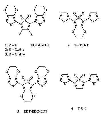 | ||
| Chart 1 | ||
The insertion of a thiophene-S,S-dioxide moiety in oligothiophenes has previously been shown to improve their photoluminescence efficiencies.6–8 It is also established that the ethylenedioxy ring improves oligothiophenes characteristics11 reducing strongly the amount of oxidative defects through capping of the 3 and 4 positions on the thiophene ring. Moreover the charge injection properties are also expected to be improved through the lowering of the oxidation potential given by the electron donor ethylenedioxy substituent.11 Our molecules, in which both these elements of molecular structure are present, seem to be good candidates as active materials in organic light-emitting devices (OLEDs).
This paper reports the synthesis of the monomers, their polymerization by anodic coupling in acetonitrile, the characterization of the polymers and the investigation of their in situ conductivity and in situ ESR behavior, namely their potential-dependent conductive and magnetic properties. Finally the photo- and electroluminescence characteristics of one of the monomeric molecular structures 2 and of its electrochemically prepared polymer poly(2) are also reported.
Results and discussion
Synthesis of the monomers
Compounds 1–4 were obtained by cross coupling reaction between the proper 2,5-dibromothiopene-1,1-dioxide and the proper 2-(tributylstannyl)thiophene in the presence of in situ generated Pd(AsPh3)4, following the procedure described in the literature for the preparation of similar compounds.5Electrosynthesis and electrochemical characterization of the polymers.
The electrochemical parameters of the monomers and of the relevant polymers are summarized in Table 1 along with the optical and conductive parameters. In the following sections the polymerization of the individual monomers are described in detail.| Monomer | E p ox; Epreda/V | E 0 ox;E0red; ΔE0/V | λ m b; λp(Eg)/nm (eV) | σ/S cm−1 |
|---|---|---|---|---|
| a Reversible process. b In CHCl3. c From ref. 2. | ||||
| 1 | 0.70; −1.60 | 0.50; −1.40; 1.9 | 463; 640 (1.95) | 0.05 |
| 2 | 0.85; −1.80 | 0.40; −1.80; 2.2 | 402; 535 (2.30) | 0.002 |
| 3 | 0.85; −1.80 | 0.50; −1.75; 2.25 | 404; 535 (2.30) | 0.004 |
| 4 | 0.78; −1.76 | 0.50; −1.60; 2.1 | 439; 605 (2.05) | 1.5 |
| 5 | 0.47; −1.90 | −0.10; −1.80; 1.7 | 452; 680 (1.80) | 2 |
| 6 c | 1.25; −1.65 | 0.75; −1.55; 2.3 | 415; 575 (2.15) | — |
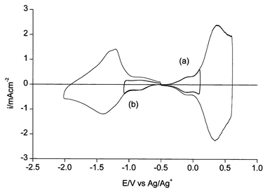
The polymer film displays a reversible oxidation process at E0 = 0.5 V (Fig. 1a). The charge yield, i.e. the ratio of reversible charge at 0.7 V (beyond 0.8 V degradation occurs) over deposition charge at the undoped state, is high (20–30%).
 | ||
| Fig. 1 Cyclic voltammograms of (a) poly(1) and (b) poly(4) in acetonitrile + 0.1 M Bu4NClO4. Scan rate: 0.1 V s−1. Reversible oxidation charge: (a) 15; (b) 1.5 mC cm−2. | ||
The polymer is also reversibly reduced at E0 = −1.40 V (Fig. 1a). The reversible charge is half the charge involved in the oxidation process if the films are thin, i.e. if the oxidation reversible charge does not exceed 10–20 mC cm−2. For thicker films the reduction reversible charge is comparatively lower probably due to a difficult permeation to cations. For this reason films thick enough for in situ conductivity (see below) were able to display their full reversible oxidation but were not practically reducible.
A comparison with the thiophene analogue 6 (see Chart 1) is worth making. The oxidation potential of poly(1) is lower than that of poly(6)5 due to the electron donor properties of the ethylenedioxy units whereas the reduction potential is somewhat higher. As a consequence poly(6)5 is reversibly oxidized and reduced with a higher energy gap (2.3 eV) than for poly(1) (1.9 eV).
 | ||
| Fig. 2 Cyclic voltammograms for (a) oxidation and (b) reduction of trapped charges in poly(1) in acetonitrile + 0.1 M Bu4NClO4. Scan rate: 0.1 V s−1. Overall reversible oxidation charge: 15 mC cm−2. | ||
Oxidation leads to the growth of the polymer film which displays reversible oxidation and reduction processes at potentials given in Table 1. The separation of the polymer redox potentials is increased in comparison with poly(1) following the decoplanarization of the structure by the substituent alkyl chains. The charge yield is low for 2 (2–4%) suggesting a strong dissolution of oxidized oligomers. Moreover the reduction process is scarcely reversible due to dissolution of the anionic oligomers thereby formed. At difference poly(3) is produced with a relatively high yield (ca. 10%) in agreement with the lower solubility of the monomer (ca. 5 × 10⁻⁴ M) in the medium. In addition the reduction is not accompanied by extensive dissolution of oligomeric anions.
The satellite redox processes shown by poly(1) are not displayed at all in the CVs of the alkylsubstituted polymers poly(2) and poly(3). This confirms that their origin lies in the non protection of the β-positions of the thiophene-S,S-dioxide ring.
Oxidation and reduction CVs of poly(4) are shown in Fig. 1b. In this case, at difference with poly(1), the reversible charges for the two processes are comparable. The charge yield of this polymer is low (ca. 5%).
The CV of 5 was performed at 50 °C in order to increase its low solubility in acetonitrile to ca. 5 × 10⁻⁴ M. Its irreversible oxidation peak is displayed at a potential (Ep = 0.47 V) even lower than that of poly(1) due to the electron donor properties of the three ethylenedioxy units. Oxidation at this potential leads to the growth of the polymer film on the anode.
The behavior of poly(5) is similar to that of poly(2) and poly(3) since it is reversibly oxidized and reduced with the same charges and no satellite CVs are displayed (the 3 and 4 positions are capped). The charge yield (ca. 50%) is higher than that of poly(1), compatible with a lower solubility of the produced oligomers. The electrochemical gap is 1.7 eV, i.e. the lowest value in the series.
Optical analysis of the polymers
With the exception of poly(2) and poly(3) (see below) the polymers are insoluble in the common solvents. The polymers in the undoped state display an absorption maximum at wavelengths given in Table 1. In the same Table the corresponding optical gap Eg is compared with the electrochemical gap given by the difference of oxidation and reduction redox potentials ΔE0. It may be observed that optical and electrochemical gaps are in fairly good agreement. With the only exception of alkylsubstituted poly(1), i.e. (poly(2) and poly(3), see below) the gaps (1.8–2.05 eV) are lower than for the thiophene-based polymer poly(6) (2.15 eV5). Moreover the trend of decreasing Eg is in the order poly(4) > poly(1) > poly(5), i.e. it decreases as the amount of ethylenedioxy units is increased. This result follows the decrease of the optical gap from polythiophene (2.3 eV14) to poly(3,4-ethylenedioxythiophene) (PEDT) (2.15 eV15).The blue polymer films turn to almost colorless when oxidized (Fig. 3) which is attributable to the low absorption in the visible range. In fact the absorbance of the doped polymer increases appreciably going from 500 to 900 nm, in contrast with doped PEDT and its alkylsubstituted derivatives which, in spite of the comparable optical gaps, display in the same region a low and almost flat response.16–19
 | ||
| Fig. 3 UV-vis spectra of (_____) undoped and (- - - -) oxidized poly(5) in acetonitrile + 0.1 M Bu4NClO4. | ||
The alkylsubstituted polymer (poly(2) and poly(3)) films, which in the undoped state display an absorption maximum at 535 nm, are to a high extent soluble in CHCl3 where a maximum at 535 nm is shown (no solvatochromic effect). According to MALDI this CHCl3-soluble polymer fraction is composed of a mixture of oligomers up to the heptamer with dominance of the trimer (DP = 3, namely 9 rings). At confirmation its 1H NMR spectrum, which resembles strictly that of the monomer (the signals are obviously broader and less resolved), gives a ratio of the integral of the aromatic signal (6.60 ppm, protons in 5 and 5″) over that of the aliphatic signal (0.90 ppm, methyl groups) corresponding to an average molecular weight of about three repeat units.
The CHCl3-insoluble alkylsubstituted polymer film shows the absorption maximum at 545 nm. The polymer is soluble in TCE where it displays the same absorption maximum. Though no MALDI spectra could be obtained, extrapolation from the maxima of the monomer and the trimer indicates a degree of polymerization DP = 8–10, i.e. 24–30 rings.
The optical gap of the CHCl3-insoluble alkylsubstituted polymers (2.3 eV) is the highest in the series and is due to the above mentioned decoplanarization of the thiophene rings operated by the alkyl substituents.
FTIR analysis of the polymers
The FTIR reflection-absorption spectrum of the undoped poly(1) film, compared with that of the monomer, shows the strong bands of the S,S-dioxide moiety at 1300 and 1140 cm−1 (1290 and 1130 cm−1 in the monomer) and of the ethylenedioxy moieties at 1080 (1170 and 1070 cm−1 in the monomer). A single C–O–C stretching band in the polymer instead of the two in the monomer has recently been shown for PEDT.20 A similar pattern is shown by the other polymers.In the case of poly(4) the polymer displays strong bands at 790 and 690 cm−1, due to the out-of-plane deformation of the inner hydrogen atoms and of the terminal hydrogen atoms respectively. The ratio of integrated intensity A690/A790 was used for an evaluation of DP by means of the empirical relationship established for polythiophenes.21 The result is that DP = 4–5, (12–15 rings) i.e. the relatively low value expected for polythiophenes.21
EQCM analysis of the polymers
EQCM analysis has been performed on the polymers with the opposite arrangements of the EDT substituents, namely poly(1) and poly(4). Correlation of EQCM dry mass and reversible charge (measured at full oxidation, 0.7 V) indicates that 1 and 0.8 electron per repeat unit respectively is exchanged during an oxidation CV cycle, as found recently for poly(bis-EDT-carbazole).22 At the same time the charge exchanged in the reduction process corresponds to 0.5 and 1.0 electron per repeat unit respectively.On the basis of these results we can formulate the following electrochemical pathway for the investigated polymers. The undoped polymers resulting from anodic coupling (two electrons per repeat unit with release of two protons) are reversibly oxidized with two electrons per two repeat units whereas they are reduced with one (for poly(1)) and two (for poly(4)) electrons per unit. Oxidation produces a bipolaron at two bithiophene subunits whereas reduction locates a polaron over one or two thiophene-S,S-dioxide moieties. ESR analysis given in the next section supports this indication.
In situ ESR of the polymers
In situ ESR of poly(1) during the oxidation process shows the appearance of a strong signal 2 G wide at g = 2.0030. The signal reaches its maximum at a potential close to the E0 value and then goes to zero (Fig. 4a). The maximum spin concentration corresponds to ca. 0.1 spins per repeat unit. The overall process is the production of rather stable radical cations (polarons) followed by their disappearance to give spinless dications (bipolarons). The fact that the maximum spin concentration is lower than 1 spin per repeat unit may be attributed to the proximity of the two subsequent one-electron processes (i.e. neutral-to-polaron and polaron-to-bipolaron) and/or to the occurrence of magnetic dimerization of the initially produced polarons.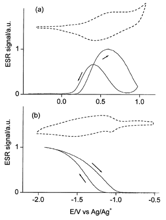 | ||
| Fig. 4 In situ ESR vs. potential for (a) oxidation and (b) reduction of poly(1) in acetonitrile + 0.1 M Bu4NClO4. Dashed curves: CVs for comparison. | ||
During the reduction a similar signal 1.5 G wide appears (Fig. 4b) at the same g = 2.0030. Also its maximum intensity is the same, ca. 0.1 spins per repeat unit. The difference is that the signal attains a plateau at full reduction. This situation corresponds to the production of stable radical anions (negative polarons). The maximum spin concentration is lower than 1 spin per repeat unit which in this case is attributable simply to the occurrence of magnetic dimerization of the negative polarons.
The g value of the radical anion is close to that measured in n-doped polythiophene, which is higher than that of the free electron (2.0023) due to interaction with the sulfur atoms.23 The fact that the same interaction is displayed in the radical cation vs. usual values around 2.002524 suggests a higher participation of the oxygen atoms from the ethylenedioxy moieties in agreement with the results obtained with PEDT.23
In situ ESR of poly(4) and poly(5) during the oxidation gives the same results (same g values and maximum spin concentrations) of poly(1).
In situ conductivity of the polymers
Given the difficulties to reduce thick deposits (see above) the conductivity of the n-doped polymer could not be measured. Conductivities of the p-doped materials were obtained regularly instead and are summarized in Table 1.The conductivity of p-doped poly(1) as a function of the applied oxidation potential appears as a distinct peak in correspondence of the redox potential (Fig. 5a), with a maximum value of 5 × 10⁻² S cm−1. These features, namely the peak shape and the low conductivity, are clear evidences of charge localization.
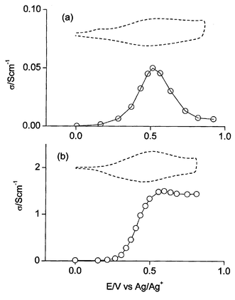 | ||
| Fig. 5 In situ conductivity vs. potential of (a) poly(1) and (b) poly(4) in acetonitrile + 0.1 M Bu4NClO4. Dashed curves: CVs for comparison. | ||
At difference the conductivity of the p-doped poly(5) and poly(4) as a function of the applied oxidation potential appears as a plateau in correspondence of the redox potential (Fig. 5b), with a maximum value of 2 and 1.5 S cm−1 respectively. In these cases no net charge localization was expected and in fact the bipolaron conductivity is high and not particularly potential limited.
The conductivities of p-doped poly(2) and poly(3) (ca. 10−3 S cm−1, see Table 1) are 10–20 times lower than that of poly(1), which is accounted for by a higher hopping distance among the polyconjugated chains.
Charge localization and conductivity
The subunits of poly(1), namely 2,2′-bis-EDT and thiophene-S,S-dioxide, are electron donors and acceptor moieties respectively. The oxidation peak potential of the 2,2′-bis-EDT molecule is 0.51 V vs. Ag/Ag+.25 Though the oxidation potential of thiophene-S,S-dioxide is not available (due to the instability of the compound) it may be roughly estimated as ca. 2.3 V from the potentials of EDT-S,S-dioxide (1.65 V26), thiophene (1.73 V27) and EDT (1.04 V22). Given the high difference of oxidation potential between the two moieties (ca. 1.7 V) the oxidation process of poly(1) may be assumed to involve the 2,2′-bis-EDT moiety only, i.e. with strong charge localization.At the opposite the subunits of poly(4), namely bithiophene and EDT-S,S-dioxide, possess much closer oxidation potentials. The oxidation peak potential of bithiophene (0.97 V27) is still negative in comparison with that of EDT-S,S-dioxide (1.65 V26) but the difference of potentials (ca. 0.6 V) is not that dramatic and charge delocalization over the whole polyconjugated chain is appreciable. A consequence of this is also the symmetry of the oxidation and reduction processes, which involve the same charges (1 electron per repeat unit).
These considerations allow an interpretation of the different conductive behavior of the investigated polymers. Thus the conductivity of poly(1) displays the potential dependence and the level characteristic of bipolaron conduction in a narrow potential window.10 In poly(4) the decrease of charge density alternation produces the sigmoid dependence of conductivity on the potential usually found in polyconjugated polymers such as e.g. PEDT and its alkylsubstituted derivatives.19
Photoluminescence and electroluminescence
The photoluminescence quantum efficiencies of the investigated monomers are similar. Also the effect of ethylenedioxy substitution on quantum yield seems to be negligible since we have found for monomer 2 (particularly investigated along with its soluble polymer, see below) an emission quantum yield of 0.8% in THF solution, which is comparable to that (ca. 1%) reported in the literature for monomer 6.4Photoluminescence (PL) and electroluminescence (EL) spectra of a single-layer OLED with TPD∶2 and TPD∶poly(2) blends as active layers (TPD = N,N′-dipheny-N,N′-bis(3-metylphenyl)-1,1′-biphenyl-4,4′-diamine, see Experimental section) are reported in Fig 6. The PL emission gives a peak at 540 nm for the TPD∶2 blend and at 650 nm for the TPD∶poly(2) blend. Both spectra are strongly red shifted with respect to the absorption ones (see Table 1).
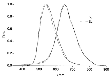 | ||
| Fig. 6 Photoluminescence (PL) spectra of the TPD∶2∶PC (left) and TPD∶poly(2)∶PC (right) films excited at 420 nm; electroluminescence (EL) spectra of the ITO/TPD∶2∶PC/Ca (solid) and ITO/TPD∶poly(2)∶PC/Ca OLEDs. All spectra are normalised. | ||
The EL spectra of both devices are entirely due to radiative decay of 2 and poly(2) excitons as no TPD emission is detected. PL and EL shapes are similar and no field effect was detected on EL spectra. The PL quantum efficiency (φPL) is ca. 1% for both blends.
External EL quantum efficiencies (φEL) as a function of applied field for both devices are reported in Fig. 7. The TPD:poly(2) device has an external EL quantum efficiency of 0.01% photon/electron at a luminance of 100 cd m−2. This value is one order of magnitude higher than that of the TPD∶2 device (Fig. 7). This result may be ascribed to a higher probability of charge recombination in poly(2) than in 2 films, due to the lower oxidation potential of the former (see Table 1). This could enhance the hole injection efficiency with the standard ITO anode (work function = 4.9 eV) thus achieving a better balance of charge injection. Alternatively the difference may be due to a different ability to create singlet molecular excitons as suggested in the recent literature.28,29
 | ||
| Fig. 7 External quantum efficiency vs. applied electric field for the ITO/TPD∶2∶PC/Ca (circles) and ITO/TPD∶poly(2)∶PC/Ca (squares) OLEDs. | ||
Conclusions
Coupling of various 3,4-ethylenedioxy-substituted 2,5-bis(2-thienyl)thiophene-S,S-dioxides in acetonitrile has produced polymers regularly alternating bithiophene and thiophene-S,S-dioxide subunits. Alternation of electron rich (ethylenedioxy) and poor (S,S-dioxide) moieties in the polythiophene chain has produced a polymer with a finite window of conductivity.Alkyl-protection of the β-positions of the thiophene-S,S-dioxide ring has given low-defect soluble oligomers which were investigated in single-layer OLEDs. Photoluminescence quantum efficiency of ca. 1% and external electroluminescence quantum efficiencies of 0.01% photon/electron were obtained at a luminance of 100 cd m−2.
Electroluminescence efficiencies are fairly low and correspond to a low photoluminescence quantum efficiency. Further molecular engineering, such as e.g. the introduction of additional alkyl chain spacers to prevent aggregation, is required to increase the emission efficiency and improve the performance of these devices.
Experimental
Chemicals and reagents
All melting points are uncorrected. All reactions of air- and water-sensitive materials were performed under nitrogen. Air- and water-sensitive solutions were transferred with double-ended needles. The solvents used in the reactions were dried by conventional methods and freshly distilled under nitrogen. Acetonitrile was reagent grade (Uvasol, Merck) with a water content <0.01%. The supporting electrolyte tetrabutylammonium perchlorate (Bu4NClO4) was previously dried under vacuum at 70 °C. 1,1′,2,2′-tetrachloroethane (TCE) and all other chemicals were reagent grade and used as received.The following compounds were prepared according to literature prescriptions: 2-(tributylstannyl)thiophene,30 2-(tributylstannyl)-3,4-(ethylenedioxy)thiophene,31 2,5-dibromothiophene-1,1-dioxide,32 2,5-dibromo-3,4-dihexylthiophene-1,1-dioxide,5 2,5-dibromo-3,4-didodecylthiophene,33 2,5-dibromo-3,4-(ethylenedioxy)thiophene.34
1H NMR spectra were recorded on a Bruker AC 300 (300 MHz for 1H); chemical shift values are given in ppm and are referred to tetramethylsilane. Electron-impact mass spectra (EI-MS) were taken on a VG 7070 EQ-HF spectrometer.
Electrochemical measurements
Experiments were performed at 25 °C under nitrogen in three electrode cells. The counter electrode was platinum; the reference electrode was a silver/0.1 M silver perchlorate in acetonitrile (0.34 V vs. SCE). The voltammetric apparatus (AMEL, Italy) included a 551 potentiostat modulated by a 568 programmable function generator and coupled to a 731 digital integrator.The working electrode for cyclic voltammetry was a platinum minidisc electrode (0.003 cm2). For electronic spectroscopy a 0.8 × 2.5 cm indium-tin-oxide (ITO) sheet (ca. 80% transmittance, ca. 20 Ω sq−1 resistance, from Balzers, Liechtenstein) was used.
FTIR spectra of the polymer films were taken in reflection–absorption mode on a Perkin Elmer 2000 FTIR spectrometer; electronic spectra were obtained from a Perkin-Elmer Lambda 15 spectrometer.
Matrix-assisted laser desorption ionization time-of-flight (MALDI-TOF) mass spectra were taken on a Reflex TOF spectrometer (Bruker) operating in the positive reflection mode, using 2,5-dihydroxybenzoic acid as the matrix.
In situ ESR spectra were taken on a Bruker ER 100D following the procedure previously described.35 Absolute spin calibration was performed with VOSO4.5H2O crystals, g-value calibration with thin films of DPPH (g = 2.0037).
Electrochemical quartz crystal microbalance (EQCM) analysis was performed with a platinum-coated AT-cut quartz electrode (0.2 cm2), resonating at 9 MHz, onto which the polymers were deposited. Absolute polymer mass measurements were performed outside the depositing solution in order to measure the mass of polymer films in the dry state as well as to avoid errors due to polymer roughness. The oscillator circuit was home-made and the frequency counter was Agilent mod.53131A.
The apparatus and procedures used in the in situ conductivity experiments were previously described in detail.36 The relevant working electrode was a two-band platinum electrode (0.3 cm × 0.01 cm for each band) with interband spacing of 20 µm, typically polymer-coated with the passage of 20 mC, which assured the attainment of limit resistance conditions.
Acknowledgements
The authors would like to thank A. Randi, S. Sitran, L. Ventura and R. Cortesi of the CNR for their technical assistance. This work was supported in part by CNR targeted project PF-MSTA II and MIUR project “Nanotecnologie” (legge 95/95).References
- C. Arbizzani, G. Barbarella, A. Bongini, L. Favaretto, M. Mastragostino, P. Ostoja, O. Pudova and M. Zambianchi, Opt. Mater., 1998, 9, 43 CrossRef CAS.
- G. Barbarella, L. Favaretto, M. Zambianchi, O. Pudova, C. Arbizzani, A. Bongini and M. Mastragostino, Adv. Mater., 1998, 10, 551 CrossRef CAS.
- G. Barbarella, O. Pudova, C. Arbizzani, M. Mastragostino and A. Bongini, J. Org. Chem., 1998, 63, 1742 CrossRef CAS.
- G. Barbarella, L. Favaretto, G. Sotgiu, L. Antolini, G. Gigli, R. Cingolani and A. Bongini, Chem. Mater., 2001, 13, 4112 CrossRef CAS.
- G. Barbarella, L. Favaretto, G. Sotgiu, M. Zambianchi, C. Arbizzani, A. Bongini and M. Mastragostino, Chem. Mater., 1999, 11, 2533 CrossRef CAS.
- G. Barbarella, L. Favaretto, G. Sotgiu, M. Zambianchi, V. Fattori, M. Cocchi, F. Cacialli, G. Gigli and R. Cingolani, Adv. Mater., 1999, 11, 1375 CrossRef CAS.
- V. Fattori, M. Cocchi, P. Di Marco, G. Giro, G. Barbarella and G. Sotgiu, Synth. Met., 2000, 111, 93 CrossRef.
- G. Gigli, G. Barbarella, L. Favaretto, F. Cacialli and R. Cingolani, Appl. Phys. Lett., 1999, 75, 439 CrossRef CAS.
- M. Zavelani Rossi, G. Lanzani, S. De Silvestri, M. Anni, G. Gigli, R. Cingolani, G. Barbarella and L. Favaretto, Appl. Phys. Lett., 2001, 79, 4082 CrossRef CAS.
- G. Zotti, S. Zecchin, G. Schiavon, A. Berlin, G. Pagani, M. Borgonovo and R. Lazzaroni, Chem. Mater., 1997, 9, 2876 CrossRef CAS.
- B. L. Groenendaal, F. Jonas, D. Freitag, H. Pielartzik and J. R. Reynolds, Adv. Mater., 2000, 12, 481 CrossRef CAS.
- G. Zotti, G. Schiavon and S. Zecchin, Synth. Met., 1995, 72, 275 CrossRef CAS and references contained therein.
- J. R. Smith, S. A. Campbell, N. M. Rathcliffe and M. Dunleavy, Synth. Met., 1994, 63, 233 CrossRef CAS.
- P. Bauerle, Adv. Mater., 1992, 4, 102.
- Q. Pei, G. Zuccarello, M. Ahlskog and O. Inganäs, Polymer, 1994, 35, 1347 CrossRef CAS.
- B. Sankaran and J. R. Reynolds, Macromolecules, 1997, 30, 2582 CrossRef CAS.
- A. Kumar, D. M. Welsh, M. C. Morvant, F. Piroux, K. A. Abboud and J. R. Reynolds, Chem. Mater., 1998, 10, 896 CrossRef CAS.
- S. A. Sapp, G. A. Sotzing and J. R. Reynolds, Chem. Mater., 1998, 10, 2101 CrossRef CAS.
- L. Groenendaal, G. Zotti and F. Jonas, Synth. Met., 2000, 118, 105 CrossRef.
- C. Kvarnstrom, H. Neugebauer, S. Blomquist, H. J. Ahonen, J. Kankare and A. Ivaska, Electrochim. Acta, 1999, 44, 2739 CrossRef CAS.
- Y. Furukawa, M. Akimoto and I Harada, Synth. Met., 1987, 18, 151 CrossRef.
- G. Zotti, S. Schiavon, S. Zecchin and L. Groenendaal, Chem. Mater., 1999, 11, 3624 CrossRef CAS.
- G. Zotti, S. Zecchin, G. Schiavon and L. Groenendaal, Chem. Mater., 2000, 12, 2996 CrossRef CAS.
- K. Kaneto, S. Hayashi, S. Ura and K. Yoshino, J. Phys. Soc. Jpn., 1985, 54, 1146 Search PubMed.
- G. A. Sotzing, J. R. Reynolds and P. J. Steel, Adv. Mater., 1997, 9, 795 CrossRef CAS.
- G. Zotti and L. Groenendaal, unpublished results.
- A. F. Diaz, J. Crowley, J. Bargon, G. P. Gardini and J. B. Torrance, J. Electroanal. Chem., 1981, 121, 355 CrossRef CAS.
- Y. Cao, I. D. Parker, G. Yu, C. Zhang and A. Heeger, Nature, 1999, 397, 414 CrossRef CAS.
- M. Wohlgenannt, K. Tandon, S. Mazumdar, S. Ramasesha and Z. V. Vardeny, Nature, 2001, 409, 494 CrossRef CAS.
- J. T. Pinhey and E. G. Roche, J. Chem. Soc., Perkin Trans. 1, 1989, 2415 Search PubMed.
- S. S. Zhu and T. M. Swager, J. Am. Chem. Soc., 1997, 119, 12568 CrossRef CAS.
- N. Furukawa, H. Hoshiai, T. Shibutani, M. Higaki and F. Fujihara, Heterocycles, 1992, 34, 1085 Search PubMed.
- F. Andreani, E. Salatelli and M. Lanzi, Polymer, 1996, 37, 661 CrossRef CAS.
- F. Tran-Van, S. Garreau, G. Louarn, G. Froyer and C. Chevrot, J. Mater. Chem., 2001, 11, 1378 RSC.
- G. Zotti and G. Schiavon, Synth. Met., 1989, 31, 347 CrossRef CAS.
- G. Zotti, A. Berlin, G. Pagani, G. Schiavon and S. Zecchin, Adv. Mater., 1995, 7, 48 CrossRef CAS.
| This journal is © The Royal Society of Chemistry 2003 |
