A new microwave ‘smart window’ based on a poly(3,4-ethylenedioxythiophene) composite
Rong
Zhang
a,
Alan
Barnes
a,
K.
Lee Ford
b,
Barry
Chambers
b and
Peter V.
Wright
*a
aDepartment of Engineering Materials, University of Sheffield, Mappin Street, Sheffield, South Yorkshire, UK S1 3JD. E-mail: p.v.wright@sheffield.ac.uk
bDepartment of Electronic and Electrical Engineering, The University of Sheffield, Mappin Street, Sheffield, South Yorkshire, UK S1 3JD
First published on 12th November 2002
Abstract
The preparation and dc and microwave characterisation of a new microparticulate mixed polymeric conductor containing poly(3,4-ethylenedioxythiophene) (PEDOT) and copper metal in a poly(ethylene oxide)–Cu(BF4)2–LiBF4 polymer electrolyte matrix is described. The composites exhibit large, rapid and reversible changes in their microwave transmission coefficients when small dc or ac fields (5–7 V) are applied radially across annular samples (13 mm o.d.) from the edges. At 1 GHz, changes of −6 dB (0 V) to −15 dB (5 V) with switching speeds of ≤250 ms were observed, and −2 to −12 dB at slower rates. Single cell experiments show that redox processes are confined to thin surface layers of the PEDOT particles. A mechanism for switching involving the polarisation of PEDOT particles under an applied field is proposed.
Introduction
Dispersions of conjugated polymers (CPs) such as poly(aniline) (PANi) and poly(pyrrole) (PPy) in insulating polymer matrices have been studied for their potential application in electromagnetic shielding (EMS) since the early 1980s.1 However, these materials show only passive (non-switchable) absorption characteristics. There is also a need for controllable microwave surfaces, or microwave ‘smart windows’; a number of approaches to solving this problem have been described in the literature and these have been reviewed by Chambers and co-workers.2–4CPs generally exhibit at least two oxidation states, neutral or uncharged forms having low conductivity and charged (usually oxidised) forms being highly conducting. The low conductivity forms of CPs are highly transmissive to microwaves, whilst the conducting forms are highly reflective. Thus, a microwave ‘smart window’ (Fig. 1) capable of controlling the transmission of microwave radiation requires that the CP is able to undergo a redox reaction under the influence of an applied stimulus. We have previously published work in this field using either PANi5or PPy6 as the CP component and silver metal as a reducing agent in a polymer electrolyte matrix comprising AgBF4 in poly(ethylene oxide) (PEO). Large, rapid and reversible changes in microwave transmission/reflection coefficients were observed when small (ca. 10 V cm−1) dc/ac fields were applied across samples of the composites (1–3 cm) from the edges in either waveguide or coaxial line test sets. The electrodes must be applied at the edges of the composite film because they have very high microwave reflection coefficients; thus redox processes must propagate across the film by some kind of ‘cascade’ process.
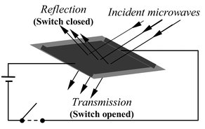 | ||
| Fig. 1 A ‘smart’ microwave window with fields applied from the edges. | ||
The composites may be described in terms of a series of microcells at the CP–polymer electrolyte interfaces, with the reducing metal particles in close proximity to the CP particles. Each microcell may be represented by the electrochemical cell,
| M|PEO–M(BF4)x–LiBF4|CP | (1) |
 | (1) |
In this paper, we present the results of our investigations on a new composite composed of poly(3,4-ethylenedioxythiophene) (PEDOT, Fig. 2) and a Cu/Cu2+ redox couple in a PEO–Cu(BF4)2–LiBF4 polymer electrolyte that shows much improved long term stability and reproducibility, presumably due to the enhanced thermal and environmental stability of PEDOT.7
 | ||
| Fig. 2 The structure of neutral PEDOT. | ||
Experimental
Synthesis of poly(3,4-ethylenedioxythiophene)
3,4-Ethylenedioxythiophene (EDOT), sold under the trade name Baytron M™, was generously donated by Bayer (UK) Ltd. and was used without further purification. All procedures were carried out at room temperature, unless otherwise stated.PEDOT was prepared using a variation of the method described by Corradi.8 To a dispersion of EDOT (0.2 g, 1.4 mmol) in distilled water (20 cm3) was added anhydrous iron(III) chloride (4.4 g, 27 mmol). The solution was stirred for 72 h, after which time the product was collected by gravity filtration, washed with distilled water until the filtrate gave a negative response to sodium thiocyanate solution (10 wt%) and then dried in vacuo. The room temperature dc conductivity of the dried, compacted product was found to be 20 S cm−1 (lit.8σrt = 20 S cm−1); yield: 80 wt%.
Another sample of PEDOT was also prepared using similar quantities of starting materials, although in this case the PEDOT product was not washed, but used as collected from the first filtration; σrt = 30 S cm−1. We hereafter describe samples from these two preparative procedures as ‘washed’ and ‘unwashed’, respectively.
Preparation of 26 wt% PEDOT microparticulate composites containing 0.85 wt% copper
The polymer electrolyte component of the composite material was prepared by dissolving PEO (0.57 g, 13 mmol; 60% molar mass = 5 × 10⁶, 40% molar mass = 3 × 10⁵) in acetonitrile (15 cm3) and stirring overnight. Copper(II) tetrafluoroborate hydrate (0.15 g, 0.63 mmol) in acetonitrile (2 cm3) was then added and stirring continued for a further 20 min.PEDOT (prepared from 0.2 g EDOT) was suspended in acetonitrile (10 cm3) and copper metal (0.015 g; average particle size <10 µm), copper(II) tetrafluoroborate hydrate (0.15 g, 0.63 mmol) and lithium tetrafluoroborate (0.12 g, 1.3 mmol) in acetonitrile (3 cm3) added. The suspension was stirred overnight and then added to the polymer electrolyte component. After stirring the composite suspension for 4 h, the solvent was removed by rotary evaporation at 40 °C and the last traces removed on the vacuum line. Some composites were prepared using ‘washed’ PEDOT whilst others were prepared using the ‘unwashed’ product.
Films of the conducting polymer composite were prepared by pressing the dried product between two steel rollers until a sample thickness of about 1 mm was achieved. Annular discs of the composites (outer diameter = 13 mm, inner diameter = 5 mm) suitable for microwave transmission measurements using a coaxial line test-set were cut out of the film. Silver conducting paint was applied to the inner and outer perimeters to ensure good electrical contact.
Preparation of single cell
The cell Pt|composite PEO–LiBF4–PEDOT|‘amorphous’ PEO–LiBF4|Cu was constructed using a composite of 40 wt% PEDOT (no Cu salts or metal). The cell was prepared by pressing the composite film (1 cm × 1 cm × 0.1 cm) onto platinum foil and completed using amorphous PEO–LiBF4 electrolyte and a Cu foil counter electrode. A branched amorphous polyether, ‘PEO/EM/AGE’, was generously supplied by the Daiso company and was used for the central polymer electrolyte electrode separator phase. The polymer electrolyte layer was deposited onto the copper electrode from an acetonitrile solution ([EO]∶[LiBF4] = 5∶1) into a window (1 cm2 ) of a 60 µm Sellotape™ spacer. | (2) |
Results and discussion
The electrochemical properties of PEDOT composites
Fig. 3 shows a plot of log10 conductivity (σ) versus composition for composites from both ‘washed’ and ‘unwashed’ PEDOT and with or without LiBF4 present in the polymer electrolyte phase. All four plots are essentially sigmoidal in form. The regions of maximum gradients between ca. 10 and 20 wt% indicate the ‘percolation thresholds’ in the various materials, at which the transport of charge becomes facilitated by a critical proximity of adjacent particles (see Fig. 4). This observation is consistent with the Scarisbrick9 theory for random walks of conducting spheres with ohmic interparticle contacts. According to this theory, a decrease of about 8 orders of magnitude in resistivity is estimated between ca. 6 and 20 vol%. Assuming a density for PEDOT particles of approximately 1.5 g cm−3 and a density of approximately unity for the matrix, the experimental data in Fig. 3 suggest percolations are in the range 8–12 vol%. This figure may be considerably less in systems with interacting particles, such as carbon in hydrocarbon rubbers in which ‘concatenation’ or ‘necklaces’ occur. In these cases, the observed percolation threshold may be as low as ca. 5 vol%. This phenomenon has been attributed to de-wetting of the particles by the matrix.10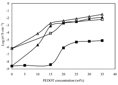 | ||
| Fig. 3 Percolation threshold of microparticulate PEDOT composites: (■) ‘washed’ PEDOT; (□) ‘washed’ PEDOT + LiBF4; (▲) ‘unwashed’ PEDOT; (△) ‘unwashed’ PEDOT + LiBF4. Measurements were performed using 5 V square waves, 0.05 Hz. | ||
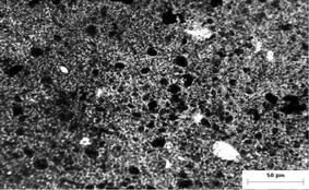 | ||
| Fig. 4 Transmission optical micrograph of ca. 10 µm thick composite film with 26 wt% PEDOT loading. | ||
The Scarisbrick theory assumes that particles are non-interacting, i.e. are well ‘wetted’ by the matrix. The optical micrograph in Fig. 4 for a 26 wt% (∼17 vol%) PEDOT composite shows that the PEDOT particles are approximately 1 µm in dimension. There are no clear indications of concatenation and it is apparent that most particles are not in physical contact with their neighbours. However, there are larger particles (5–10 µm), some of which are Cu metal particles (as shown by SEM), and also clusters of PEDOT particles.
Thus, the presence of the LiBF4 apparently has little influence on the critical percolation compositions of either ‘washed’ or ‘unwashed’ composites. However, LiBF4 clearly has a significant influence on the conductivities of the ‘washed’ composites, raising the conductivities by a factor of ca. 103 throughout the range of compositions. In the case of the ‘unwashed’ material, however, it is only below the percolation composition that LiBF4 increases the conductivity. At percolation and above, the ‘unwashed’ composites, with and without the added salt, have similar conductivities. A plausible explanation for this observation is that the ‘excess’ FeCl3 carried on the surface of the ‘unwashed’ particles migrates to the polymer electrolyte phase, promoting the conductivity of this phase. {From gravimetric analysis, it was estimated that for the ‘unwashed’ composite at a composition just above the percolation region (ca. 25 wt% PEDOT/PEO + PEDOT), the concentration of FeCl3 in the electrolyte phase corresponds to a molar composition of [FeCl3]∶[ether oxygen] ≅ 1∶7.}
Fig. 5 shows resistance versus voltage for annular samples (13 mm outer diameter, 5 mm inner diameter) of 26 wt% PEDOT composites prepared from ‘washed’ and ‘unwashed’ microparticulate PEDOT, both containing Cu, Cu(BF4)2 and LiBF4. As shown in Fig. 5(ii), from which plot b in Fig. 5(i) was constructed, the current reaches a maximum in 0.25 s or less. Fig. 5(i) shows that both composites are non-ohmic for applied potentials of 0 to ca. 2 V, but greater field dependence is seen with the ‘unwashed’ material. Above 2 V, both materials have similar resistances.
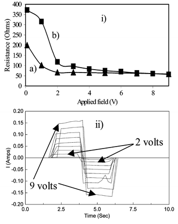 | ||
| Fig. 5 The dependence of resistance on applied field for the annular samples of PEDOT–Cu(BF4)2–LiBF4–Cu composite films containing 26 wt% of PEDOT; molar ratio of EDOT∶Cu metal = 6∶1. (i) ‘Washed’ PEDOT composite (a), ‘unwashed’ PEDOT composite (b). (ii) Square waves of frequency 0.25 Hz, from which plot b for the unwashed sample was obtained. | ||
According to Fig. 3, both composites are above the percolation thresholds, although there are differences in their resistance changes with potential. The composite with ‘unwashed’ PEDOT is more resistive at low fields and, so, shows the larger change between 0.1 and 2 V in Fig. 5(i). With further increases in applied voltage, the resistance decreases only slightly in both samples.
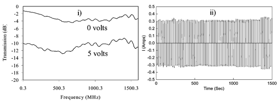 | ||
| Fig. 6 Microwave transmission of ‘washed’ PEDOT composite film measured using a coaxial line analyser with square waves of 0 and 5 V applied: (i) change in microwave transmission coefficient; (ii) applied square wave. | ||
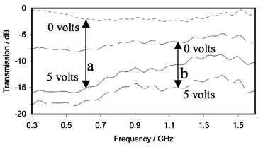 | ||
| Fig. 7 Microwave transmission of ‘unwashed’ PEDOT composite film measured using a coaxial line analyser: (a) field applied using cyclic voltammetry, 50 mV s−1; (b) field applied using square wave, 0.05 Hz. | ||
All of the experiments suggest greater changes at 300 MHz. In Fig. 7(a), for example, the change from ca. −0.3 to −16 dB corresponds to an impedance change from ca. 710 to 4.5 Ω. The origins of this frequency dependence are not clear. It may reflect features of the composite structure (particle size, matrix conductivity, etc.). Alternatively, modelling of the coaxial experiment suggests that the phenomenon may arise from inductive effects due to the creation of highly conducting pathways (‘wires’) having resistances significantly lower than most of the area of the disc.
Any change of temperature within the discs as a consequence of the currents passed are not considered to be responsible for the observed changes in resistivities and microwave transmission. This was tested by independently raising the temperature of a composite disc using warm air and measuring its resistance. A negligible temperature coefficient for the conductivity of the composite material over the range 20–55 °C was observed. The temperature of the sample in situ in the coaxial line was also measured with a square wave current of 0.5 A, and the temperature rise was found to be well within this range with a maximum of ca. 35 °C. Furthermore, the thermal capacity of the system should have ensured that the steady-state temperature was constant and could not follow the observed rapid changes in microwave transmission. Finally, it is noted from Fig. 5 that the largest changes in resistance take place at lower fields, becoming almost constant above 2 V, where larger increases in temperature might have been anticipated.
Single cell experiment
Fig. 8 shows a cyclic voltammogram for a cell incorporating a PEDOT composite electrode, Pt|composite PEO–LiBF4–PEDOT/PEO + LiBF4|Cu, at a scan rate of 2 mV s−1. The polymer electrolyte in the composite has the same composition as that of the central ‘separator’ phase. Although oxidation and reduction peaks can be discerned, it is apparent that they are very indistinct and that the redox process (eqn. 1) takes place only to a minimal degree. From the area under the peaks and the dimensions of the electrode (1 cm × 1 cm × 0.1 cm) it may be estimated that only ca. 0.01% of the PEDOT in the composite electrode partakes in the exchange. Assuming that this is distributed uniformly throughout all the particles of the electrode, it must be concluded that only the surface layer of each PEDOT particle is involved. A solvent-free cell incorporating an electrodeposited polyaniline film versus Ag and using an “amorphous PEO” electrolyte was observed by Despotakis11 to give a cyclic voltammogram having better defined redox peaks. However, the peak areas similarly demonstrated that only the surface layer of the film (ca. 20 Å) was involved in the exchange. This is to be anticipated in a solvent-free system in which the polymer electrolyte is incapable of swelling the conjugated polymer particles so that the migration of counterions into the interior of the particles is very slow. These observations suggest that the mechanism of rapid switching observed in the microwave transmission measurements involves only exchange of charge at the PEDOT–polymer electrolyte interface.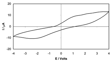 | ||
| Fig. 8 Cyclic voltammogram of single cell Pt|composite|PEO + LiBF4|Cu; scan rate 2 mV s−1. | ||
A proposed mechanism for switching
The composites described in this paper contain 26 wt% (∼17 vol%) of PEDOT. Although this composition is greater than the critical percolation compositions in Fig. 3, Fig. 4 suggests that the PEDOT particles are, for the most part, uniformly dispersed as ‘islands’ in the polymer electrolyte matrix, with little evidence for ‘necklaces’ of directly contacting particles. Indeed, composites with PANi11,12 or PEDOT contents in excess of ca. 45 wt% (in which considerable particle–particle contacts might be anticipated) have high conductivities but do not allow field control of the microwave transmission/reflection. On the other hand, we have already reported significant changes in microwave impedance in PANi composites containing as little as 10 wt% of the CP in the PEO matrix.12 This indicates that field-controlled microwave switching requires a low degree of particle–particle contact. However, local contacts could assist in propagating the applied field across the film. It may therefore be concluded that the process takes place by both particle polarisation and percolation processes.The redox components M/Mn+ are also essential for the observation of field-controlled behaviour and the presence of the supporting electrolyte, LiBF4, is required for rapid, reproducible and sustainable cycling, particularly in the case of ‘washed’ composites. However, from the single cell experiments, we conclude that the redox processes may take place only on the surfaces of the particles, particularly during the higher frequency application of the alternating fields.
These experimental observations suggest a tentative schematic model for the composite material, as shown in Fig. 9. In the absence of the applied field, the core of each particle remains in the higher conductivity state, but the skin adopts the low conductivity form as a consequence of reduction by the metal [Fig. 9(a) and eqn. 1]. In the presence of the applied field, neighbouring particles become polarised in the direction of the field [Fig. 9(b)]. [It is significant that we have observed no microwave activity with the polymeric counterion polystyrene sulfonate, which would be unable to migrate as required by Fig. 9(b).] If the polarisation is sufficiently strong, this should result in electron transfer across the interface to the transition metal ion. The stabilisation of the conducting form in a given particle [Fig. 9(c)] in the CP skin layer should be promoted by the ready availability of counter ions in the polymer electrolyte phase, as well as by the corresponding polarisation within adjacent particles and in the surrounding medium. Such a process might commence in particles close to an electrode, but rapidly percolate across the material. Long sequences of similarly polarised particles with appropriately polarised double layers and hopping between redox states in the interparticle medium may allow uninterrupted long range displacements of charge by the incident microwaves. Following removal of the field, thermal disorder would allow random polarisation of the particles and the return of the electron to the conjugated polymer particles.
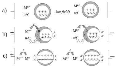 | ||
| Fig. 9 Schematic representations of proposed mechanism for changes in composite impedance with applied field: (a) at zero field; (b) showing particle polarisation under applied field; (c) electron transfer from particle to redox metal ion under applied field. | ||
The role of the surface skin of the particles is perhaps reflected in the differences in the behaviour of the ‘washed’ and ‘unwashed’ materials. The presence of Fe3+/Fe2+ in the polymer electrolyte and at the surface layer of the ‘unwashed’ particles should promote electron transfer across the interface, bringing about a more resistive surface skin in the ‘off’ state. With redox ions in place at the interface, the electron transfer may require only minimum displacements of counterions between their roles opposing the oxidised forms of the conjugated polymer or the transition metal ion. Electron hopping between redox states in the PEO matrix should also promote charge transfer in the interparticle medium.
The plausibility of the proposed scheme will be tested by observing the anisotropy of the change in microwave transmission when polarised microwaves are incident either parallel or normal to the direction of the applied field. The influence on performance of transport promoters in the PEO medium [e.g. aluminium tris(8-hydroxyquinolinate) and arylamines] will also be investigated. The results of these experiments will be reported in due course.
Conclusions
Electrochemical and microwave measurements on a PEDOT–Cu–{PEO–Cu(BF4)2–LiBF4} composite containing 26 wt% PEDOT have been carried out. The results show that the application of a small dc or low frequency ac electric field across the edges of annular samples of the composite gives rise to large, rapid and reversible changes in the dc and microwave impedances. Electrochemical switching between the “off” and “on” states occurs at applied fields as low as 2 V and with switching times of ≤250 ms. Single cell experiments indicate that only a thin layer of the PEDOT particles may be electrochemically active within the PEO medium. The largest changes in microwave impedance were observed in samples with residual FeCl3. The composites show reproducible switching for several hundred cycles. A schematic model for the mechanism of switching, involving polarisation of individual particles and the redox reaction of the thin surface layers, creating double or multiple layers of ions in the region of the particle surfaces, is proposed. Long sequences of similarly polarised particles may be stabilised by the formation of the ion layers, allowing long range charge displacements within the incident microwave fields.Acknowledgements
The authors wish to thank Bayer (UK) Ltd. for the generous donation of the Baytron M™ monomer and the Daiso Company for the generous donation of the “amorphous PEO”. We also thank Mr E. Giri of the Department of Engineering Materials, University of Sheffield, for his assistance with the optical microscopy. We gratefully acknowledge the EPSRC and QinetiQ for financial support through grant number GR/M88754. We would also like to acknowledge the assistance of the ORS scheme for the award of a studentship to R. Z.References
- J. Roncali, Chem. Rev., 1992, 92(4), 711–738 CrossRef CAS and references therein.
- B. Chambers, Smart Mater. Struct., 1997, 6, 521–529 CrossRef.
- B. Chambers, Smart Mater. Struct., 1999, 8, 64–72 CrossRef.
- B. Chambers and K. L. Ford, Electron. Lett., 2000, 36(15), 1304–1306 CrossRef.
- A. Barnes, K. Lees, P. V. Wright and B. Chambers, Proc. SPIE-Int. Soc. Opt. Eng., 1999, 3675, 139–149 Search PubMed.
- A. Barnes, K. L. Ford, P. V. Wright, B. Chambers, C. D. Smith, D. A. Thompson and F. Pavri, Proc. SPIE-Int Soc. Opt. Eng., 2000, 4073, 109–120 Search PubMed.
- F. Jonas and G. Heywang, Electrochim. Acta, 1994, 39(8–9), 1345–1347 CrossRef CAS.
- R. Corradi and S. P. Armes, Synth. Met., 1997, 84, 453–454 CrossRef CAS.
- R. M. Scarisbrick, J. Phys. D, 1973, 6, 2098 Search PubMed.
- B. Wessling, Proceedings of the Conductive Polymers Conference 1992, University of Bristol, RAPRA Technology Ltd, Shrewsbury, UK, 1992, paper 4 Search PubMed.
- A. Despotakis, Mixed Polymer Conductors for Control of Microwave Reflective Surfaces, PhD thesis, University of Sheffield, UK, 1998 Search PubMed.
- P. V. Wright, B. Chambers, A. Barnes, K. Lees and A. Despotakis, Smart Mater. Struct., 2000, 9, 273–279 CrossRef CAS.
| This journal is © The Royal Society of Chemistry 2003 |
