Fischer–Tropsch synthesis over cobalt catalysts supported on mesoporous alumino-silicate
Mingdeng
Wei
*a,
Kiyomi
Okabe
a,
Hironori
Arakawa
a and
Yasutake
Teraoka
b
aNational Institute of Advanced Industrial Science and Technology, Tsukuba Central #5, Ibaraki 305-8565, Japan. E-mail: wei-mingdeng@aist.go.jp; Fax: +81 298 61 4487
bDepartment of Applied Chemistry, Faculty of Engineering, Nagasaki University, Nagasaki, 852-8521, Japan
First published on 9th January 2002
Abstract
Mesoporous alumino-silicate (MPAS) was prepared at ambient temperature by utilizing hexadecylpyridinium chloride as a surfactant, and used as the support of cobalt catalysts for Fischer–Tropsch synthesis in a slurry phase. The results of XRD and N2 adsorption measurements indicate that cations such as Co2+ and Ir4+ were effectively loaded on the surface of the mesopore walls, retaining mesoporous characteristics. The Co–Ir catalyst supported on MPAS showed excellent thermal stability, higher selectivity for C10–20 hydrocarbons and lower selectivity for CH4. These properties are affected by Al incorporated into the silica framework.
The discovery of a series of mesoporous silicate molecular sieves (M41S) having regular porous size distributions between 2 and 10 nm has greatly expanded the capacities of heterogeneous catalysis in comparison with zeolite materials, and these M41S materials have been used as the catalyst or support for many catalytic reactions.1–3 MCM-41 has a uniform hexagonal array of linear channels constructed with a honeycomb-like silica matrix, and the channel diameter can be tailored by the choice of surfactant. It can be expected that MCM-41 is effective for ready diffusion of feed gas and products, and chain growth in Fischer–Tropsch (F–T) synthesis. Up to now, only several papers have been concerned with mesoporous materials as the support for F–T synthesis catalysts. Su et al.4 used ZrO2 supported on MCM-41, Al-MCM-41 and HMS as catalysts for F–T synthesis and obtained higher selectivity for C2 to C4 hydrocarbons. The above-mentioned mesoporous materials were also utilized Yin et al.5 as the support to prepare Co-supported catalysts for F–T synthesis; they reported that higher selectivity for C5+ hydrocarbons was obtained and that CO conversion was 92.5%. Iwasaki et al.6 reported that a Co catalyst supported on the mesoporous silicate SCMM had higher CO conversion than Co on silica gel. In these systems, the catalytic properties were evaluated in a fixed bed reactor and the role of mesoporous material supports as well as supported metals were thoroughly investigated. However, the effect on catalytic performance of Al incorporated into the silica framework has not been reported. In this paper, Co–Ir supported on mesoporous alumino-silicates has been investigated for F–T synthesis in the slurry phase, and the influence on the catalytic properties of Al incorporated into the silica framework is discussed.
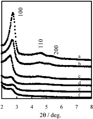
XRD patterns of mesoporous alumino-silicates (MPAS), as well as mesoporous silicate (MPS) synthesized by the same method,7 are depicted in Fig. 1, curves a and b. They show three peaks in the region 2θ![[thin space (1/6-em)]](https://www.rsc.org/images/entities/char_2009.gif) =
=![[thin space (1/6-em)]](https://www.rsc.org/images/entities/char_2009.gif) 2–8°, corresponding to the (100), (110) and (200) reflections of a typical hexagonal lattice, indicating that MPAS and MPS are structurally analogous to MCM-41.8 It is important to mention that the position of the main peak varies significantly depending on the synthesis conditions, and on the type of Si and Al sources. When aluminum is incorporated into the framework, the spacing of the (100) reflection shifts from the 3.2 nm found in purely siliceous MPS to the 3.3 nm of MPAS with a Si/Al ratio of 29. The interplanar spacing of the MPAS material is higher than that of the pure silicate MPS material, and increases with the amount of aluminum incorporated. This is consistent with the incorporation of increasing amounts of tetrahedral Al into the MPS framework, due in part to the longer Al–O bond length (1.75 Å) compared to the Si–O bond (1.60 Å). On the other hand, with the increase in aluminum content, the (100) diffraction peak becomes broader and less intense. The effect of the incorporation of aluminum into the framework is clearly indicated by the changes in the thickness of the pore walls (calculated by subtracting the pore diameter from the lattice parameter). N2 adsorption–desorption isotherms of MPAS and MPS exhibit a isotherm of type IV with a sharp step at the relative pressure 0.2
2–8°, corresponding to the (100), (110) and (200) reflections of a typical hexagonal lattice, indicating that MPAS and MPS are structurally analogous to MCM-41.8 It is important to mention that the position of the main peak varies significantly depending on the synthesis conditions, and on the type of Si and Al sources. When aluminum is incorporated into the framework, the spacing of the (100) reflection shifts from the 3.2 nm found in purely siliceous MPS to the 3.3 nm of MPAS with a Si/Al ratio of 29. The interplanar spacing of the MPAS material is higher than that of the pure silicate MPS material, and increases with the amount of aluminum incorporated. This is consistent with the incorporation of increasing amounts of tetrahedral Al into the MPS framework, due in part to the longer Al–O bond length (1.75 Å) compared to the Si–O bond (1.60 Å). On the other hand, with the increase in aluminum content, the (100) diffraction peak becomes broader and less intense. The effect of the incorporation of aluminum into the framework is clearly indicated by the changes in the thickness of the pore walls (calculated by subtracting the pore diameter from the lattice parameter). N2 adsorption–desorption isotherms of MPAS and MPS exhibit a isotherm of type IV with a sharp step at the relative pressure 0.2![[thin space (1/6-em)]](https://www.rsc.org/images/entities/char_2009.gif) <
<![[thin space (1/6-em)]](https://www.rsc.org/images/entities/char_2009.gif) P/P0
P/P0![[thin space (1/6-em)]](https://www.rsc.org/images/entities/char_2009.gif) <
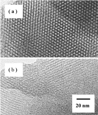
<![[thin space (1/6-em)]](https://www.rsc.org/images/entities/char_2009.gif) 0.3, which is due to capillary condensation inside the mesopores. The transmission electron micrographs (TEM) of MPAS and MPS show that the (100) direction still retains a regular hexagonal array of uniform channels, characteristic of mesoporous MCM-41 (see Fig. 2).
0.3, which is due to capillary condensation inside the mesopores. The transmission electron micrographs (TEM) of MPAS and MPS show that the (100) direction still retains a regular hexagonal array of uniform channels, characteristic of mesoporous MCM-41 (see Fig. 2).
 | ||
| Fig. 1 Powder XRD patterns of (a) MPS, (b) MPAS with a Si/Al ratio of 29, (c) 1 wt% Ir–5 wt% Co/MPAS, (d) 1 wt% Ir–10 wt% Co/MPAS, (e) 1 wt% Ir–15 wt% Co/MPAS, (f) used 1 wt% Ir–10 wt% Co/MPAS catalyst. | ||
 | ||
| Fig. 2 TEM images of (a) MPAS with a Si/Al ratio of 19 and (b) MPS. | ||
A series of Co–Ir catalysts supported on MPAS with a Si/Al ratio of 29 (1 wt% Ir–x wt% Co/MPAS) was prepared by the impregnation or evaporation-to-dryness methods, in which x is 5, 10 or 15. Their crystal structure was checked by powder X-ray diffraction (XRD) using Cu-Kα irradiation, as shown in Fig. 1, curves c–e. The (100) peak was observed for all samples, though the intensity decreased remarkably with Co content, indicating a considerable lowering in structural regularity. The results of N2 adsorption measurements showed that all of these catalysts have a well-defined mesoporous distribution, although their peak height decreased slightly. The 1 wt% Ir–10 wt% Co/MPAS catalyst employed was calcined at 400![[thin space (1/6-em)]](https://www.rsc.org/images/entities/char_2009.gif) °C for 5 h in order to remove residual wax, and then was checked by XRD, as shown in Fig. 1, curve f. The intensity of the (100) peak was almost unchanged, indicating that the mesoporous structure can be retained after F–T synthesis. Table 1 lists the mesopore parameters of the samples mentioned above. The interplanar spacing (d100) was almost unchanged after cation loading, but the surface area decreased from 1202 to 678 m2 g−1 upon loading up to 15 wt% Co. The pore size gradually decreased with Co content, resulting in an obvious increment of pore wall thickness. In view of the results mentioned above, we suggest that the metal ions, Co2+ and Ir4+, are effectively loaded on the surface of the mesopore walls.
°C for 5 h in order to remove residual wax, and then was checked by XRD, as shown in Fig. 1, curve f. The intensity of the (100) peak was almost unchanged, indicating that the mesoporous structure can be retained after F–T synthesis. Table 1 lists the mesopore parameters of the samples mentioned above. The interplanar spacing (d100) was almost unchanged after cation loading, but the surface area decreased from 1202 to 678 m2 g−1 upon loading up to 15 wt% Co. The pore size gradually decreased with Co content, resulting in an obvious increment of pore wall thickness. In view of the results mentioned above, we suggest that the metal ions, Co2+ and Ir4+, are effectively loaded on the surface of the mesopore walls.
| Samplea | d 100/nm | Unit cell parameterb/nm | S BET/m2 g−1 | Pore volume/cm3 g−1 | Pore diameter/nm | Wall thickness/nm |
|---|---|---|---|---|---|---|
a
Si/Al![[thin space (1/6-em)]](https://www.rsc.org/images/entities/char_2009.gif) = =![[thin space (1/6-em)]](https://www.rsc.org/images/entities/char_2009.gif) 29 in all samples.
b
Unit cell parameter 29 in all samples.
b
Unit cell parameter![[thin space (1/6-em)]](https://www.rsc.org/images/entities/char_2009.gif) = =![[thin space (1/6-em)]](https://www.rsc.org/images/entities/char_2009.gif) (2/√3) (2/√3)![[thin space (1/6-em)]](https://www.rsc.org/images/entities/char_2009.gif) · ·![[thin space (1/6-em)]](https://www.rsc.org/images/entities/char_2009.gif) d100 d100![[thin space (1/6-em)]](https://www.rsc.org/images/entities/char_2009.gif) = =![[thin space (1/6-em)]](https://www.rsc.org/images/entities/char_2009.gif) Pore diameter + Wall thickness. Pore diameter + Wall thickness.
|
||||||
| MPAS | 3.4 | 3.9 | 1202 | 1.10 | 3.66 | 0.24 |
| 1 wt% Ir–5 wt% Co/MPAS | 3.4 | 3.9 | 825 | 0.76 | 3.66 | 0.24 |
| 1 wt% Ir–10 wt% Co/MPAS | 3.4 | 3.9 | 778 | 0.65 | 3.32 | 0.52 |
| 1 wt% Ir–15 wt% Co/MPAS | 3.3 | 3.8 | 678 | 0.52 | 3.08 | 0.72 |
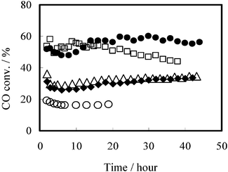
The F–T synthesis was carried out in a slurry phase over Co–Ir catalysts supported on MPAS, and the reaction results are shown in Fig. 3. It indicates that CO conversion increases drastically when noble metal Ir is added to the Co catalysts, due to the increased reducibility of surface Co on the catalysts.9,10 On the other hand, the catalytic activity over Ir–Co/MPAS catalyst was more stable than that over Ir–Co/MPS catalyst, and insignificant deactivation was observed, even after a reaction time of more than 44 h.
 | ||
Fig. 3 Time course of the Fisch–Tropsch synthesis in slurry phase. (O) 20 wt% Co/MPS, (□) 0.5 wt% Ir–20 wt% Co/MPS, (△) 0.5 wt% Ir–20 wt% Co/MPAS (Si/Al![[thin space (1/6-em)]](https://www.rsc.org/images/entities/char_2009.gif) = =![[thin space (1/6-em)]](https://www.rsc.org/images/entities/char_2009.gif) 49), (♦)1 wt% Ir–20 wt% Co/MPAS (Si/Al 49), (♦)1 wt% Ir–20 wt% Co/MPAS (Si/Al![[thin space (1/6-em)]](https://www.rsc.org/images/entities/char_2009.gif) = =![[thin space (1/6-em)]](https://www.rsc.org/images/entities/char_2009.gif) 49), (●) 1 wt% Ir–20 wt% Co/MPAS (Si/Al 49), (●) 1 wt% Ir–20 wt% Co/MPAS (Si/Al![[thin space (1/6-em)]](https://www.rsc.org/images/entities/char_2009.gif) = =![[thin space (1/6-em)]](https://www.rsc.org/images/entities/char_2009.gif) 19). 19). | ||
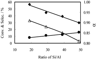
The effects of Al in the MPAS framework are shown in Fig. 4. It is obvious that the catalytic activity is enhanced by Al, resulting in increased CO conversion as well as chain growth probability α, while CH4 selectivity was restrained. The influence of Al on the F–T product distribution is shown in Table 2. The selectivity for C10–20 hydrocarbons increased by almost twofold, even when only a small amount of Al was incorporated into the framework. When the Si/Al ratio was 19, the selectivity for C10–20 hydrocarbons was 38.5%, while CH4 selectivity was only 8.2%.
 | ||
| Fig. 4 Effect of Al in the silica framework on the product distribution in F–T synthesis: (♦) CO conversion, (●) CH4 selectivity, (△) chain growth probability α. | ||
| Selectivity for | ||||||
|---|---|---|---|---|---|---|
| Catalyst (Si/Al ratio) | CO conv. | CH4 | C2–4 | C5–9 | C10–20 | α a |
| a The chain growth probability α was calculated from a Schultz–Flory distribution. | ||||||
| 20 wt% Co/MPS | 16.5 | 18.5 | 14.4 | 22.0 | 12.2 | 0.76 |
| 0.5 wt% Ir–20 wt% Co/MPS | 50.8 | 14.2 | 25.2 | 27.7 | 13.0 | 0.76 |
| 20 wt% Co/MPAS (19) | 49.2 | 8.0 | 10.4 | 16.9 | 30.6 | 0.88 |
| 0.5 wt% Ir–20 wt% Co/MPAS (49) | 32.7 | 12.7 | 10.7 | 17.0 | 26.0 | 0.84 |
| 1 wt% Ir–20 wt% Co/MPAS (49) | 29.9 | 15.9 | 14.5 | 21.1 | 23.7 | 0.81 |
| 1 wt% Ir–20 wt% Co/MPAS (39) | 39.1 | 12.2 | 11.8 | 18.9 | 29.3 | 0.85 |
| 1 wt% Ir–20 wt% Co/MPAS (29) | 44.7 | 11.2 | 10.4 | 17.2 | 31.1 | 0.88 |
| 1 wt% Ir–20 wt% Co/MPAS (19) | 56.6 | 8.2 | 9.2 | 16.4 | 38.5 | 0.91 |
In order to elucidate the effect of the Al state in the catalysts on F–T synthesis, four types of Al-containing supports were used: (A) MPAS (Si/Al![[thin space (1/6-em)]](https://www.rsc.org/images/entities/char_2009.gif) =
=![[thin space (1/6-em)]](https://www.rsc.org/images/entities/char_2009.gif) 29), (B) MPS impregnated with Al (Si/Al
29), (B) MPS impregnated with Al (Si/Al![[thin space (1/6-em)]](https://www.rsc.org/images/entities/char_2009.gif) =
=![[thin space (1/6-em)]](https://www.rsc.org/images/entities/char_2009.gif) 29), (C) SiO2 impregnated with Al (Si/Al
29), (C) SiO2 impregnated with Al (Si/Al![[thin space (1/6-em)]](https://www.rsc.org/images/entities/char_2009.gif) =
=![[thin space (1/6-em)]](https://www.rsc.org/images/entities/char_2009.gif) 29), and (D) commercial SiO2–Al2O3
(Si : Al
29), and (D) commercial SiO2–Al2O3
(Si : Al![[thin space (1/6-em)]](https://www.rsc.org/images/entities/char_2009.gif) =
=![[thin space (1/6-em)]](https://www.rsc.org/images/entities/char_2009.gif) 1 : 9). The synthesis results are summarized in Table 3. Catalyst A showed higher CO conversion, C10–20 selectivity and chain growth probability α, and lower CH4 selectivity than the others. In addition, the reaction was more stable over catalyst A for a long time, while serious deactivation occurred over catalysts B, C and D. The difference in the state of Al between catalysts A and B/C is that Al in the former is incorporated into the silica framework, forming a tetrahedral coordination with oxygen, while in the latter two it is in the form of Al2O3. As for catalyst D, there might be too much Al in the support SiO2–Al2O3, which caused deactivation as well as lower selectivity for C10–20 hydrocarbons.
1 : 9). The synthesis results are summarized in Table 3. Catalyst A showed higher CO conversion, C10–20 selectivity and chain growth probability α, and lower CH4 selectivity than the others. In addition, the reaction was more stable over catalyst A for a long time, while serious deactivation occurred over catalysts B, C and D. The difference in the state of Al between catalysts A and B/C is that Al in the former is incorporated into the silica framework, forming a tetrahedral coordination with oxygen, while in the latter two it is in the form of Al2O3. As for catalyst D, there might be too much Al in the support SiO2–Al2O3, which caused deactivation as well as lower selectivity for C10–20 hydrocarbons.
| Selectivity for | ||||||
|---|---|---|---|---|---|---|
| Catalyst (Si/Al ratio) | CO conv. | CH4 | C2–4 | C5–9 | C10–20 | α a |
| a The chain growth probability α was calculated from a Schultz–Flory distribution. | ||||||
| A: 1 wt% Ir–15 wt% Co/MPAS (29) | 45.4 | 10.8 | 13.5 | 21.9 | 29.9 | 0.85 |
| B: 1 wt% Ir–15 wt% Co–1.3 wt% Al/MPS (29) | 39.1 | 13.9 | 20.7 | 28.0 | 20.8 | 0.78 |
| C: 1 wt% Ir–5 wt% Co–1.2 wt% Al/SiO2 (29) | 40.0 | 11.7 | 13.2 | 24.2 | 26.6 | 0.81 |
| D: 1 wt% Ir–20 wt% Co/SiO2–Al2O3 (1/9) | 39.1 | 17.4 | 18.0 | 29.9 | 21.3 | 0.76 |
In summary, mesoporous alumino-silicate (MPAS) as a catalyst support has been used for F–T synthesis in the slurry phase. The characterization results show that the cations Co2+ and Ir4+ are effectively loaded on the surface of the mesopore walls and that the materials still retain a mesoporous structure. Compared with mesoporous silicate (MPS) and SiO2 supports, the thermal stabilization of MPAS was obviously enhanced; this might be attributed to Al incorporated into the silica framework. F–T synthesis over Co–Ir catalysts supported on MPAS showed that CO conversion and selectivity for C10–20 hydrocarbon products increased and selectivity for CH4 was effectively restrained.
Experimental
Synthesis of mesoporous alumino-silicate
Hexadecylpyridinium chloride (C16PyCl) was used as the cationic surfactant in the synthesis of mesoporous alumino-silicate.11 The typical procedure is as follows: C16PyCl (3.0 mmol) was dissolved in 52 ml of water. With vigorous stirring and optional heating, appropriate amounts of HCl and NaOH, in a molar ratio of (Si![[thin space (1/6-em)]](https://www.rsc.org/images/entities/char_2009.gif) +
+![[thin space (1/6-em)]](https://www.rsc.org/images/entities/char_2009.gif) Al) : surfactant : NaOH : HCl : H2O
Al) : surfactant : NaOH : HCl : H2O![[thin space (1/6-em)]](https://www.rsc.org/images/entities/char_2009.gif) =
=![[thin space (1/6-em)]](https://www.rsc.org/images/entities/char_2009.gif) 1 : 0.12 : 1.06–1.27 : 0.61 : 141, were added in order to adjust the pH of the surfactant solution below or above 11, depending on the amounts of acid and base. Clear solutions of the required amount of sodium silicate (Na2·2SiO2·nH2O) and aluminum nitrate [Al(NO3)3·9H2O] were added dropwise into the surfactant solution at room temperature with vigorous stirring. After further stirring for 3 h at room temperature, the precipitated product was filtered, washed thoroughly with water, dried in an oven at 383 K for 6 h, and finally calcined in air at 873 K for 6 h in order to remove the template.
1 : 0.12 : 1.06–1.27 : 0.61 : 141, were added in order to adjust the pH of the surfactant solution below or above 11, depending on the amounts of acid and base. Clear solutions of the required amount of sodium silicate (Na2·2SiO2·nH2O) and aluminum nitrate [Al(NO3)3·9H2O] were added dropwise into the surfactant solution at room temperature with vigorous stirring. After further stirring for 3 h at room temperature, the precipitated product was filtered, washed thoroughly with water, dried in an oven at 383 K for 6 h, and finally calcined in air at 873 K for 6 h in order to remove the template.
Preparation of cobalt catalysts
The required amounts of Co(NO3)3·6H2O and IrCl4·H2O were dissolved in de-ionized water, and then dispersed completely onto the mesoporous materials using impregnation or the evaporation-to-dryness methods. The obtained solid mixture was calcined at 573 K for 1 h in order to decompose remaining nitrate.Characterization of mesoporous materials and cobalt catalysts
X-Ray powder diffraction (XRD) patterns were recorded using a diffractometer (Mac Science, MPX-18). Multi-point BET surface area, pore volume and BJH pore size distribution of materials were calculated from the adsorption-desorption isotherm of N2 at 77 K (Micromeritics, ASAP 2000). Transmission electron micrographs were taken on a JEOL instrument.Fischer–Tropsch reaction
After reduction at 673 K for 15 h in H2 flow, the catalyst (2 g) was crushed into fine powder in 50 ml of n-hexadecane, and suspended into a slurry. The F–T reaction was carried out with the catalyst slurry in an autoclave-type semi-batch reactor (flow type for gas phase), whose volume was approximately 100 ml. The feed gas (H2 : CO : Ar![[thin space (1/6-em)]](https://www.rsc.org/images/entities/char_2009.gif) =
=![[thin space (1/6-em)]](https://www.rsc.org/images/entities/char_2009.gif) 60 : 30 : 10) was bubbled through the slurry, and the dissolution of the gas in the slurry was promoted by a specially designed stirring rod.12 The reaction conditions were as follows: T
60 : 30 : 10) was bubbled through the slurry, and the dissolution of the gas in the slurry was promoted by a specially designed stirring rod.12 The reaction conditions were as follows: T![[thin space (1/6-em)]](https://www.rsc.org/images/entities/char_2009.gif) =
=![[thin space (1/6-em)]](https://www.rsc.org/images/entities/char_2009.gif) 503 K, P
503 K, P![[thin space (1/6-em)]](https://www.rsc.org/images/entities/char_2009.gif) =
=![[thin space (1/6-em)]](https://www.rsc.org/images/entities/char_2009.gif) 1 MPa and W/F
1 MPa and W/F![[thin space (1/6-em)]](https://www.rsc.org/images/entities/char_2009.gif) =
=![[thin space (1/6-em)]](https://www.rsc.org/images/entities/char_2009.gif) 10 g catal h mol−1. The effluent gas was periodically analyzed by using Shimadzu on-line gas chromatographs (models 14B and 17A) with TCD and FID detectors; inorganic gases and C1–14 hydrocarbons were determined using Ar in the sample gas as the internal standard. The C10+ hydrocarbons in the slurry were determined separately by gas chromatography after the reaction.
10 g catal h mol−1. The effluent gas was periodically analyzed by using Shimadzu on-line gas chromatographs (models 14B and 17A) with TCD and FID detectors; inorganic gases and C1–14 hydrocarbons were determined using Ar in the sample gas as the internal standard. The C10+ hydrocarbons in the slurry were determined separately by gas chromatography after the reaction.
Acknowledgements
We thank JSPS for financial support (contract no. JSPS-RFTF98P01001).References
- S. Zheng, L. Gao, Q.-h. Zhang and J.-k. Guo, J. Mater. Chem., 2000, 10, 723 RSC.
- A. Liepold, K. Roos, W. Reschetilowski, A. P. Esculcas, J. Rocha, A. Philippou and M. W. Anderson, J. Chem. Soc., Faraday Trans., 1996, 92, 4623 RSC.
- X. Chen, L. Huang, G. Ding and Q. Li, Catal. Lett., 1997, 44, 123 Search PubMed.
- C. Su, Y. Zou, W. Pan, D. He and Q. Zhu, Ranliao Huaxue Xuebao, 1998, 16, 297 Search PubMed.
- D. Yin, W. Li, B. Zhong and S. Peng, Chin. J. Catal., 2000, 21, 221 Search PubMed.
- T. Iwosaki, M. Reinikainen, Y. Onodera, H. Hayashi, T. Ebina, T. Nagase, K. Torii, K. Kataja and A. Chatterjee, Appl. Surf. Sci., 1998, 130–132, 845 CrossRef.
- Y. Setoguchi, Y. Teraoka, I. Moriguchi and S. Kagawa, J. Porous Mater., 1997, 4, 129 Search PubMed.
- C. T. Kresge, M. E. Leonowizc, W. J. Roth, J. C. Vartuli and J. S. Beck, Nature (London), 1992, 359, 710 CrossRef CAS.
- K. Okabe, X. Li, T. Matsuzaki, M. Toba, H. Arakawa and K. Fujimoto, Sekiyu Gakkaishi, 1999, 42, 377 Search PubMed.
- T. Matsuzaki, K. Takeuchi, T. Hanaoka, H. Arakawa and Y. Sugi, Catal. Today, 1996, 28, 251 CrossRef CAS.
- Y. Teraoka, Y. Fukunaka, Y. Setoguchi, I. Moriguchi and S. Kagawa, in Adsorption Science and Technology, ed. D. Do, World Scientific, Singapore, 2000, p. 603. Search PubMed.
- L. Fan, Y. Z. Han, K. Yokota and K. Fujimoto, Sekiyu Gakkaishi, 1999, 39, 111 Search PubMed.
| This journal is © The Royal Society of Chemistry and the Centre National de la Recherche Scientifique 2002 |
