DOI:
10.1039/B003682J
(Feature Article)
J. Mater. Chem., 2001,
11, 37-53
Geometrically frustrated magnetic materials†
Received
10th May 2000
, Accepted 23rd June 2000
First published on 15th November 2000
Abstract
The current state of efforts to understand the phenomenon of geometric magnetic frustration is described in the context of several key materials. All are transition metal oxides which crystallize with magnetic lattices which are geometrically or topologically prone to frustration such as those based on triangles or tetrahedra which share corners, edges or faces. These include the anhydrous alums, jarosites, pyrochlores, spinels, magnetoplumbites, garnets, ordered NaCl and other structure types. Special attention is paid to materials which do not undergo long range ordering at the lowest temperatures but instead form exotic ground states such as spin glasses, spin liquids and spin ices, and to S = 1/2 based materials.
Introduction
Magnetism has played a central role in the solid state chemistry of transition metal compounds. Intensive studies during the 1950s led for example to breakthrough accomplishments in understanding the fundamentals, such as the discovery of the Goodenough–Kanamori rules governing the sign and magnitude of exchange in insulators, and to applications such as the utilization of spinel structure ferrite materials in the embryonic stages of electronic information technology. Recent attention has been focussed on materials in which the magnetism is coupled strongly to the transport properties. Antiferromagnetic correlations are clearly implicated in the as yet incompletely understood mechanism behind the cuprate superconductors . Magnetic double exchange is critical to the so-called “colossal” magnetoresistive manganates which were re-discovered in the mid 1990s. The subject of this brief review is geometrically frustrated antiferromagnetic (GFAF) materials. The conditions for magnetic frustration are satisfied in many real materials and the effects of frustration are present in the magnetic properties but not always appreciated. Excellent examples are the lithium battery cathode oxides which are beginning to be studied for their remarkable magnetic as well as electrochemical properties. On a more fundamental level, GFAF materials have attracted much attention over the past few years due to their propensity to adopt unusual, even exotic magnetic ground states which remain poorly understood. The most successful research efforts in this area are broadly interdisciplinary, drawing upon the talents of specialists in synthesis, characterization and theory.
Geometric magnetic frustration
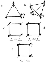
Toulouse1 is often credited with introducing the general concept of magnetic frustration, a term applied to the situation wherein a large fraction of magnetic sites in a lattice is subject to competing or contradictory constraints, although specific cases had been identified even earlier, for example by Anderson.2 When frustration arises purely from the geometry or topology of the lattice it is termed geometric frustration. The canonical example is any lattice based on an equilateral triangular “plaquette”, Fig. 1a, which depicts the situation for the three nearest neighbour spins. As the Hamiltonian for the interaction between any two spins can be written as a scalar product of the spin operators,| |  | (1) |
the energy is minimized for collinear (parallel or antiparallel) spin alignments. Under the conditions that J is negative which favours the antiparallel (antiferromagnetic) correlation and that J is equal for all n.n. (nearest neighbour) pairs, it is clear that only two of the three spin constraints can be satisfied simultaneously, i.e., the system is geometrically frustrated. This can be contrasted with the situation for the square planar plaquette, Fig. 1c, which is clearly not frustrated under the same constraints.
 |
| | Fig. 1
Frustrated “plaquettes”: a) the equilateral triangle, b) the tetrahedron, c) the square plane with Jnn ≫ Jnnn, d) square plane with Jnnn ≫ Jnn, e) square plane with Jnn ∼ Jnnn.
| |
While the above is a convenient illustrative example, frustration is not confined to two dimensions nor even, strictly, to triangular plaquettes. The tetrahedron, Fig. 1b, is a polyhedron comprised of four edge-sharing equilateral triangles and is also geometrically frustrated as now, only two of the four equivalent n.n. interactions can be satisfied, simultaneously. Even the square plaquette can be rendered frustrated if n.n. and n.n.n. (next-nearest neighbour) interactions are considered, Fig. 1c and d, for the special case of Jnn ∼ Jnnn, Fig. 1e.
Geometrically frustrated lattices
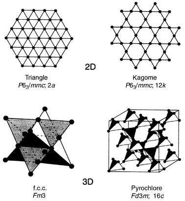
The preceding discussion has concerned only the plaquettes which must be connected by the sharing of corners, edges or even faces (in the case of tetrahedra) to form the lattices which appear in real materials. Some examples of frustrated lattices are shown in Fig. 2, the corner and edge shared triangular and the corner and edge sharing tetrahedral lattices. This is not an exhaustive listing but many real materials, as discussed later, can be understood in terms of one or more of these arrays. Specialized terms for three of the lattices have become standard, the corner shared triangular lattice is the Kagome lattice (for a distinctive Japanese basket weave pattern), the edge shared tetrahedral lattice is also the f.c.c. (face-centred cubic) lattice and the corner shared tetrahedral lattice, which comprises the 16c or 16d sites in space group Fd3m and occurs in both spinel and pyrochlore structure materials, has come to be known as the pyrochlore lattice. For the strictly planar lattices, the mode of stacking in three dimensions can confer additional frustration as for example in the case of …ABAB… or …ABCABC… stacking of edge shared triangular sheets with antiferromagnetic interplanar exchange, Jinter < 0. As well, …ABCABC… stacking of Kagome layers yields the pyrochore lattice, Fig. 3.
 |
| | Fig. 2
Some common frustrating lattices.13
| |
![The pyrochlore lattice as a stacking of Kagome layers. (top) View normal to the stacking direction. (bottom) View along the stacking direction [1 1 1] of the cubic pyrochlore cell.](/image/article/2001/JM/b003682j/b003682j-f3.gif) |
| | Fig. 3
The pyrochlore lattice as a stacking of Kagome layers. (top) View normal to the stacking direction. (bottom) View along the stacking direction [1 1 1] of the cubic pyrochlore cell.
| |
Manifestations of geometric frustration
The primary source of the growing interest in frustrated magnetic systems arises due to the many unusual modes by which the presence of the frustration is expressed. All systems of interest are sufficiently concentrated that magnetic interactions are expected on an energy scale set by the exchange energy, Hex ∼ −2JS2 ∼ kT, where T ≫ 0. A simple experimental measure of the exchange energy is provided by the familiar Weiss constant, θc, which appears in the Curie–Weiss law,| |  | (2) |
From the mean field theory3 it can be shown that| |  | (3) |
where n is the nth neighbour and Jn, the corresponding exchange constant, i.e.θc is the algebraic sum of all of the exchange interactions in any magnetic system and thus the Weiss constant sets the energy scale for the magnetic interactions. In the absence of frustration one expects the onset of strong deviations from the Curie–Weiss law for T ∼ |θc| and the establishment of a long range ordered state also near |θc|. For ferromagnetic order this is nearly realized, as |θc|/Tc ∼ 1. Tc is the critical temperature below which the long range ordered state is established. For antiferromagnetic order the situation is a bit more complex and the ratio depends on the exact magnetic structure which is adopted but typical values for non-frustrated lattices show |θc|/Tc values in the range of 2 to 4 or 5. For example |θc|/Tc for the LnCrO3 perovskites in which the magnetic sublattice is non-frustrated, simple cubic, ranges from 2 to 3.4
It has, thus, been proposed that the somewhat arbitrary condition, |θc|/Tc > 10, be taken as a criterion for the presence of frustration.5 As will be soon shown, in the case of ground states which are not long range ordered, such as spin glasses, a freezing temperature, Tf, is substituted for Tc.
Ground states of frustrated magnets—long range order
According to the current ideas of phase transitions and critical phenomena, the possibility that a long range ordered state can be realized in any magnetic system, in the absence of frustration, is determined by the dimensionality of both the lattice, d, and the spin, D.6D is equal to the number of spin components which must be considered in the expanded form of eqn. (1), i.e.| |  | (4) |
The case of D = 1 means that only one component is important and is known as the Ising model, D = 2 is the X–Y model and D = 3 is the isotropic Heisenberg model. With the famous exception of D = 1, d = 2 (2d Ising model), only systems with d = 3 will undergo true long range order. The presence of a frustrated lattice complicates this situation.
Non-collinear ground states
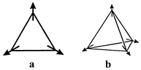
Most frustrated systems which do undergo true phase transitions to a long range ordered state adopt so-called non-collinear or compromise spin configurations. The canonical example is for the triangular lattice in which the three spins, Fig. 4a, are aligned at 120° which results in a vector sum of zero for the plaquette and the lattice, thus, globally satisfying the antiferromagnetic constraint. The corresponding compromise configuration for the tetrahedral plaquette and pyrochlore lattice is the 109° structure of Fig. 4b. In both cases there is more than one way to achieve these non-collinear configurations which introduces degeneracy, due to chirality, into the ground state. It should be noted that the case of Ising spins (D = 1) on the triangular lattice cannot adopt the compromise structure, two spins can be aligned antiparallel but one will remain uncoupled.
 |
| | Fig. 4
Compromise non-collinear magnetic structures: (a) the 120° structure on a triangular plaquette, (b) the 109° structure on a tetrahedral plaquette.
| |
For real materials the 120° structure is found quite commonly for triangular planar lattices while the 109° structure has been reported only for one pyrochlore lattice compound, py-FeF3.7 Materials with the chemical pyrochlore structure, e.g. Y2Mo2O7, often adopt short range ordered ground states and materials with the chemical spinel structure, ZnFe2O4 for example, adopt very complex spin orderings with large magnetic unit cells as will be discussed in following sections. For the spinels the influence of interactions well beyond the n.n. level is thought to be important.
Before moving on it is worth noting that attempts have been made to rank some of the common lattices in terms of the level of geometric frustration. LaCorre8 has proposed a constraint function:
| |  | (5) |
where
Eb is the “basis” energy for a non-frustrated pair-wise interaction and
E is the energy of the frustrated spin pair.
Eb can be rewritten as
| |  |
(6)
|
and
| |  |
(7)
|
where
p is the number of spins in a cluster (for
p > 2) and
eb is the normalized energy per cluster. Thus
Fc =
e/
eb = −1/(
p−1) and
Fc = −1 defines a non-frustrated system while
Fc becomes more positive as the frustration level increases. A list of selected lattices and the corresponding
Fc values are displayed in
Table 1.
Table 1
Selected constraint functions for frustrated lattices8
| Lattice (compound) |
F
c
|
| Simple cubic (rhomb FeF3) |
−1.0 |
| Frustrated square (+++−) |
−0.707 |
| Helimagnet (β-MnO2) |
−0.552 |
| AF triangular |
−0.500 |
| AF icosahedral cluster |
−0.447 |
| Pyrochlore (cubic FeF3) |
−0.33 |
On this basis the pyrochlore lattice is quantitatively more frustrated, p = 4, Fc = −1/3, than the triangular planar lattice, p = 3, Fc = −1/2, as one might have deduced, qualitatively, from Fig. 1a and b.
Ground states without long range order—cooperative paramagnets, spin glasses, spin ices and spin liquids
Many materials with frustrated lattices do not exhibit a phase transition to a long range ordered state. This is particularly true for tetrahedral, pyrochlore lattice compounds but is found for many other materials as well. From a microscopic point of view it has long been recognized that such lattices possess an enormous degeneracy. For example, any configuration in which all tetrahedra are, separately, in a minimum energy state is a ground state. This can be obtained for the case wherein each tetrahedron has two pairs of antiparallel spins but there is no correlation between tetrahedra. There exists an enormous number of such configurations and no unique, long range ordered state can emerge. Villain has chosen to describe such systems with the oxymoronic label, “cooperative paramagnet”.9 The inclusion of the term paramagnetic here also implies that such a system is dynamic, i.e. spin fluctuations should persist at all temperatures. These ideas have been tested at many levels of theory and all possible spin dimensionalities and the accepted consensus result is that the pyrochlore lattice with n.n. antiferromagnetic interactions does not support static, long range order above 0 K.10
The essentially infinite degeneracy of the perfect, n.n. pyrochlore lattice can of course be perturbed by inclusion of other complicating factors such as interactions beyond n.n.’s, dipolar coupling, defects in the lattice, etc. These effects can work to select a ground state or set of states which will may or may not be Neel states. The most commonly observed non-Neel state is the spin glass.
Spin glasses
Microscopically, the spin glass state is a configuration of spins frozen into a more or less random pattern. There exists a distinct freezing or glass temperature, Tf or Tg, below which the random, frozen state is established from a random fluctuating state. There will be a huge number of frozen states, separated by tiny energy differences, so the exact ground state found is determined by the experimental conditions and hysteresis will be observed. Experimentally, there are many signatures of the spin glass state and among the most commonly (and easily) observed are (1) a field-cooled (FC), zero field-cooled (ZFC) divergence below Tf, in the d.c. magnetic susceptibility, (2) a strong frequency dependence in the a.c. susceptibility, both χ′ and χ″, below Tf, (3) a T1 dependence of the electronic contribution to the heat capacity at very low temperatures, (4) a sharp decrease in the spin fluctuation or spin relaxation time as measured by inelastic neutron scattering, muon spin relaxation or some other technique sensitive to spin dynamics below Tf, (5) the absence of long range order from neutron diffraction.
Spin liquids and spin ices
Other ground states discussed frequently in the context of GFA materials, but observed much less frequently, are the spin liquid and the “spin ice”. Spin liquids are the same as cooperative paramagnets and differ from spin glasses in that no distinct Tf is observed, i.e. the spins or a large fraction of spins remain dynamic down to the lowest temperatures. Spin liquids are often discussed in the case of S = 1/2, i.e. quantum spin systems, due to ideas from Anderson in which an unusual ground state consisting of spin-paired singlets, the so-called Resonating Valence Bond state, has been proposed.11 The term RVB is borrowed from Pauling in analogy to his Valence Bond model for the chemical bond.
Also borrowed from Pauling is the term “spin ice”.12 This is a special case of the spin liquid formed by Ising spins on a tetrahedral (pyrochlore) lattice and maps exactly onto the problem of the distribution of protons around the O atoms in solid, hexagonal ice. Pauling was able to explain the excess entropy found at low temperatures for ice in terms of this extra degeneracy. There is a prediction that Sex = kB[ln(2) − 1/2 ln(3/2)].
The remainder of this review will consist of brief case studies of selected GFAF materials. The emphasis will be on oxides and on studies in which chemists have made important contributions and less on other materials which have been well described in earlier reviews of this subject.5,13 The discussion will begin with frustrated 2d lattice systems and progress to 3d lattices. Special attention will be paid to S = 1/2 based materials as this has been a topic of enduring interest.
2d Lattice materials
The anhydrous alums.
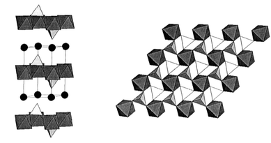
The vast library of mineral structures has long been a valuable source of materials for solid state chemists. The anhydrous alums (mineral name yavapaiite) have composition AIMIII(SO4)2, where A is a group I element and M is a trivalent transition metal ion. The structure is shown in Fig. 5. The space group may be trigonal, P![[3 with combining macron]](https://www.rsc.org/images/entities/char_0033_0304.gif) , for A = Cs and Rb or distorted to monoclinic, C2/m, for A = K or Na. The M sublattice is perfect edge shared equilateral triangular (ET) for the trigonal form and isosceles triangular (IT) for the monoclinic alums with for example angles of 64.60, 57.70 and 57.70° for KFe(SO4)2. The layer stacking is …AAA…, so 3d interlayer frustration is not an issue. Relevant magnetic data are listed in Table 2.
, for A = Cs and Rb or distorted to monoclinic, C2/m, for A = K or Na. The M sublattice is perfect edge shared equilateral triangular (ET) for the trigonal form and isosceles triangular (IT) for the monoclinic alums with for example angles of 64.60, 57.70 and 57.70° for KFe(SO4)2. The layer stacking is …AAA…, so 3d interlayer frustration is not an issue. Relevant magnetic data are listed in Table 2.
 |
| | Fig. 5
The crystal structure of the anhydrous alums, A+B3+Fe(SO4)2. The black spheres are the A+ ions, the SO42− tetrahedra are in white and the BO6 octahedra are in grey; (left)—view normal to the c-axis, (right)—view parallel to the c-axis.
| |
Table 2
Magnetic parameters for the anhydrous alums, AM(SO4)214,15
| Compound |
S
|
θ
c/K |
T
c/K |
|θc|/Tc |
| CsFe(SO4)2 |
5/2 |
−34.17 |
4.4 |
7.8 |
| RbFe(SO4)2 |
5/2 |
−29.12 |
4.2 |
6.9 |
| KFe(SO4)2 |
5/2 |
−55.5 |
8.3 |
6.7 |
| KTi(SO4)2 |
1/2 |
−10.2 |
<1.2 |
>10 |
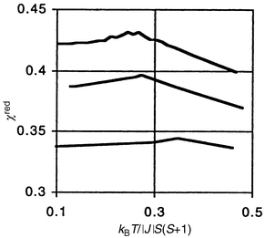
Both θc and Tc are low due to the convoluted superexchange pathways through the SO42− groups, nonetheless, the |θc|/Tc ratios are large and consistent with a high level of frustration. Comparison of the reduced susceptibilities with Monte Carlo simulations by Kawamura et al.16 for the 2d Heisenberg model on the triangular lattice show excellent agreement, Fig. 6, and thus the ferric alums qualify as model compounds.
 |
| | Fig. 6
Reduced susceptibility versus reduced temperature for CsFe(SO4)2
(upper curve) and RbFe(SO4)
(middle curve) compared with a Monte Carlo simulation for a classical Heisenberg AF on a triangular lattice (bottom curve).15
| |
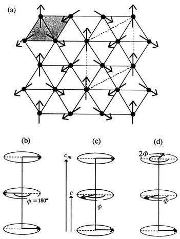
The ferric alums all show long range order at finite temperatures and have been studied by neutron diffraction. For A = Cs and Rb, three possible structures have been proposed.15 Each involves planes of 120° coupled spins stacked along the c-axis and rotated by various angles as seen in Fig. 7. The A = K phase has a very different and complex, incommensurate magnetic structure which consists of sine-wave modulated spins formed on adjacent rows of Fe3+ on the apices of the isosceles triangles, Fig. 8.
 |
| | Fig. 7
Three models for the magnetic structure of CsFe(SO4)2 and RbFe(SO4)2. The spin structure in the plane, (a), is the same, q = 0, but the rotation of the planes between the stacked layers is different, (b)–(d).15
| |
![The sine wave modulated magnetic structure on the isosceles triangular lattice of monoclinic KFe(SO4)2. The spins lie along the [1 1 1/2] and [−1 −1 −1/2] directions and (+ or −) and the amplitude is modulated along [1 −1 0].15](/image/article/2001/JM/b003682j/b003682j-f8.gif) |
| | Fig. 8
The sine wave modulated magnetic structure on the isosceles triangular lattice of monoclinic KFe(SO4)2. The spins lie along the [1 1 1/2] and [−1 −1 −1/2] directions and (+ or −) and the amplitude is modulated along [1 −1 0].15
| |
The S = 1/2 compound, KTi(SO4)2, is potentially the most interesting member of the series and the one for which, lamentably, the least is known. It shows the largest |θc|/Tc ratio and in fact no long range order down to 1.2 K. A broad susceptibility maximum centered at about 3.5 K is indicative of short range correlations. This material merits further investigation, especially specific heat and spin dynamics studies at low temperature, to investigate the possibility of spin liquid behaviour.
Frustrated square lattice.
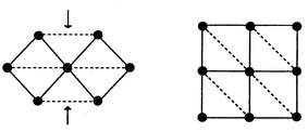
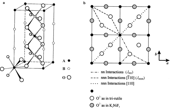
Bramwell has shown that the square lattice with Jnn ≠ Jnnn maps onto the problem just described, the edge sharing isosceles triangular (IT) lattice, Fig. 9.14 Real materials which may represent the frustrated square lattice are the series of trirutile structure oxides, AIIB2VO6, where A is a divalent transition metal and B = Ta or Sb, Fig. 10a. Because of the positioning of the oxide ligands in the AO planes, Fig. 10b, the condition Jnnn > Jnn can be realized. The stacking of the AO planes results in an I-centered A sublattice which can lead to interplanar frustration but the actual distance between A ions is not unusually long, 6.5 Å, in comparison with the alums for example where the distance is the c-axis length, ∼8 Å. In Table 3 selected magnetic data for the trirutile oxides are presented. The last entry, k, is the ordering wave vector for the long range ordered magnetic structure disclosed by neutron diffraction. The (1/2 0 1/2) structure is one in which the spins within each AO plane (001) are antiparallel along the square face diagonal and represents the case wherein Jnnn dominates Jnn, Fig. 1d. The much more complex (1/4 1/4 1/4) structure has the spins turning by 90° for each chemical cell translation in both the a and c directions and is consistent with Jnnn ∼ Jnn. This can be regarded as a commensurate spiral.17 These observations are consistent with the closest theory relevant to these materials, due to Zhang et al., who studied the XY model on the IT lattice.18 While it is not clear if any of these ions approximates to an XY case, theory finds the (1/2 0 1/2) model, called the “row” model, for Jnnn/Jnn > 2 and a spiral structure for Jnnn/Jnn < 2. Note that the non-collinear spiral is found for the cases wherein the |θc|/Tc frustration index is largest.
 |
| | Fig. 9
The topological equivalence of the isosceles triangular (IT) (left) and the square lattice with Jnnn ≫ Jnn (right).14
| |
 |
| | Fig. 10
The trirutile structure, AB2O6 (left), and the exchange pathways in the ab plane (right). The ligand positions in the trirutile planes are compared with those in the K2NiF4 structure.
| |
Table 3
Selected magnetic data for the trirutile oxides, ATa2O617
| Compound |
θ
c/K |
T
c/K |
|θc|/Tc |
k
|
| VTa2O6 |
−56 |
21(1) |
2.7 |
(1/2 0 1/2) |
| CrTa2O6 |
−40 |
10(1) |
4.0 |
(1/4 1/4 1/4) |
| FeTa2O6 |
−11 |
8.1 |
1.4 |
(1/2 0 1/2) |
| CoTa2O6 |
−33 |
6.6 |
5.0 |
(1/4 1/4 1/4) |
| NiTa2O6 |
−44 |
10.3 |
4.3 |
(1/4 1/4 1/4) |
Discussion of one additional, much studied, edge shared ET lattice, Li1 ± xNi1 ± xO2, will be deferred to a later section on S = 1/2 materials and we now turn to Kagome lattices.
The Kagome lattice.
The physical realization of a Kagome lattice represents an elusive target. One material which had been extensively promoted, the magneto-plumbite structure oxide SrGa12 − xCrxO19
(SCGO), is better described as a Kagome–pyrochlore hybrid with incomplete occupation of the Kagome net.19 SCGO will be discussed later.
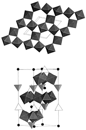
Again the mineral world provides a potentially better model in the form of jarosite structure materials with nominal composition AFe3(SO4)2(OH)6, where A = Na+, K+, Rb+, Ag+, Tl+, NH4+, H3O+, 1/2Pb2+ or 1/2Hg2+. Cr3+, In3+, Al3+ or Ga3+ can substitute for Fe3+.20,21 This is an idealized formulation, extensive protonation of the OH− sites can occur which results in vacancies on the Fe net. One exception appears to be the hydronium salt for which ∼98% coverage of the Fe sites can be realized. Thus, careful attention to synthetic details (hydrothermal methods are typically required) and thorough characterization are both requisites with jarosite materials. The crystal structure, which can be described in R![[3 with combining macron]](https://www.rsc.org/images/entities/char_0033_0304.gif) m, is shown in Fig. 11. The Kagome layers, Fig. 11(top), consist of corner sharing FeO6 octahedra in a distinctive pattern involving triangular and hexagonal “holes”also found in the pyrochlore structure. While the FeO octahedra are clearly puckered, the Fe ions form a perfectly planar Kagome net. The layer stacking sequence is …ABCABC… along the c-axis and the FeO layers are well separated, 6 Å, by sulfate, hydroxide and A-site ions, Fig. 11(bottom).
m, is shown in Fig. 11. The Kagome layers, Fig. 11(top), consist of corner sharing FeO6 octahedra in a distinctive pattern involving triangular and hexagonal “holes”also found in the pyrochlore structure. While the FeO octahedra are clearly puckered, the Fe ions form a perfectly planar Kagome net. The layer stacking sequence is …ABCABC… along the c-axis and the FeO layers are well separated, 6 Å, by sulfate, hydroxide and A-site ions, Fig. 11(bottom).
 |
| | Fig. 11
The jarosite structure, AB3(SO4)2(OH)6. (Top) View of a corner sharing BO6 layer; (bottom) view normal to the c-axis, the A+ ions are black spheres, the SO42− tetrahedra are in white and the BO6 octahedra in grey. The OH groups are not shown.
| |
To date most work has been reported for the A = H3O+, Fe3+-based jarosite but Fe3+ site “doped” materials have also been studied along with several A-site substitutions and one Cr3+ based compound. Table 4 collects some basic magnetic properties for several jarosites for which the Kagome site occupation rate has been determined analytically. Note that the θc values are large, negative and roughly independent of the coverage rate. Remarkably, the “ordering” temperatures increase as the Kagome-site coverage rate decreases. This phenomenon will be discussed in more detail later.
Table 4
Magnetic properties for several jarosite phases with various Kagome-site coverages21,22,23
| Nominal composition |
Kagome site coverage (%) |
θ
c/K |
T
f,c/K |
|θc|/Tc/K |
| (D3O)Fe(SO4)2(OD)6 |
97(1) |
−700(5) |
13.8 |
51 |
| (D3O)Fe3 − xAly(SO4)2(OD)6 |
89(3) |
−720(5) |
25.5 |
28 |
| (ND4)Fe3(SO4)2(OD)6 |
91(3) |
−640(5) |
46, 62 |
14, 10 |
| NaFe3(SO4)2(OD)6 |
95(4) |
−667(5) |
42, 62 |
16, 11 |
| AgFe3(SO4)2(OD)6 |
89(3) |
−677(4) |
51 |
13 |
| RbFe3(SO4)2(OD)6 |
87(3) |
−688(5) |
47 |
15 |
| KFe3(SO4)2(OH)6 |
89(3) |
−600 |
46 |
13 |
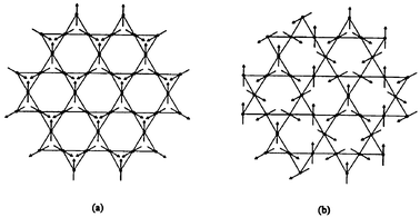
A discussion of the ground state for the jarosites divides neatly into two categories, (D3O)Fe3(SO4)2(OD)6 and all the others. Taking the second category first, it is now well established that all of these materials show long range order in spite of the 10% or higher concentration of vacancies on the Kagome net. In all cases for which data exist the so-called q = 0 structure, Fig. 12(a), is found to describe the ab plane spin configuration, and the controversy concerning the stacking of the layers has been resolved.20,24 This can involve either ferromagnetic or antiferromagnetic interlayer spin correlations, the former resulting in a doubling of the magnetic c-axis, i.e., cmag = 2cchem.
 |
| | Fig. 12
Spin structures on the Kagome lattice. (a) q = 0, (b) q = √3 × √3.
| |
Note also that for some materials two transition temperatures, often obtained from NMR experiments, are reported, Table 4. The origin of this phenomenon is not understood. In one case where neutron diffraction data were collected over the range covering both transitions, NaFe3(SO4)2(OD)6, no clear signature of the lower transition could be observed.24
A surprising result from the ordered jarosites is the universality of the q = 0 structure, in spite of both quantum and classical theories for the Kagome lattice which predict that the larger q = √3 × √3 structure, Fig. 12(b), should be favoured.25 It is possible that the interplanar interactions can exert control of the intraplanar spin configuration.
At this stage the situation of the Cr-jarosites is relevant. Although much less studied than the Fe-based materials, one phase, KCr3(SO4)2(OD)6, has been examined in some detail.20,26 For this case samples have been prepared with Cr-site coverages from ∼100% to 76%. Both θc = −68 K and Tc = 1.8 K are much lower than for the corresponding Fe-phase but the frustration ratio is still large, ∼40. Again, the q = 0 magnetic structure is found but the ordered Cr moment is only 1.1(3) μB, about 1/3 of the saturation value of 3 μB
(S = 3/2). This contrasts with Fe3+ moments (S = 5/2) near 80% of the expected value for the iron jarosites20 and illustrates the increasingly drastic effect of frustration with decreasing S.
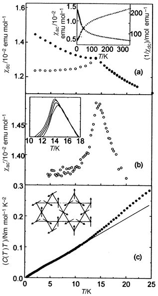
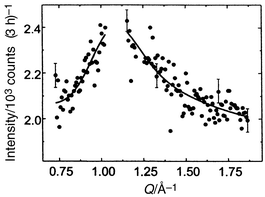
Let us return to the best studied jarosite, (D3O)Fe3(SO4)2(OD)6. In sharp contrast to all other cases, this material shows no long range order down to 1.4 K in spite of an apparent transition at 13.8 K, in both the d.c. and a.c. susceptibility (Fig. 13).27 The appearance of these data suggest a spin glass type behaviour. Other anomalous results are the observation of a T2 dependence of the specific heat at low temperatures, unlike the T1 law often seen for spin glasses but mimicking that found for SCGO. No resolution limited magnetic Bragg peaks are found in this compound down to 1.9 K but diffuse magnetic scattering is evident. Fig. 14 shows the highly asymmetric, diffuse peak centered at about Q = 1.1 Å−1.27,28 This peak has the Warren line shape characteristic of scattering from two dimensional objects, with a sharp increase at low Q followed by a gradual decrease to higher Q. This peak is thus assigned to scattering from uncorrelated Kagome layers. Analysis shows that the intraplanar spin–spin correlation length is 19(2) Å. This value of Q is in excellent agreement with Monte Carlo simulations for the antiferromagnetic Kagome lattice.29
 |
| | Fig. 13
Magnetic and thermal data for (D3O)Fe3(SO4)2(OD)6: (a) d.c. susceptibility, (b) a.c. susceptibility, (c) specific heat data showing a T2 dependence at low temperature.27
| |
 |
| | Fig. 14
Diffuse magnetic scattering for (D3O)Fe(SO4)2(OD)6 at 1.5 K. The fit is to a Warren line shape and Bragg peaks have been subtracted.27
| |
The spin dynamics of this system have also been studied using the neutron spin echo technique.30 Gradual spin freezing has been observed as the sample is cooled below Tf ∼ 13 K until at 2 K the spins are static at time scales up to 870 ps. This behaviour is typical of spin glasses and has also been observed in SCGO.
Finally, the observation that the deuteronium salt with nearly 100% Kagome site occupation is not ordered, while all of the other jarosites with a lesser coverage rate do order, led Harrison and Wills to propose an “order by disorder” mechanism.22 In an elegant test of this hypothesis, a sample of (D3O)Fe3 − xAly(SO4)2(OD)6 was prepared with 89% Kagome site coverage. For this material, Table 4, Tf rises to 25.5 K and long range order was detected by neutron diffraction at 1.4 K. There is at present no theoretical basis for understanding this phenomenon. It is worth mentioning here that Tf appears to fall slightly with Kagome site dilution in the Cr-based jarosites.
3d Lattices
Pyrochlore.
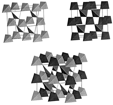
The pyrochlore lattice is realized in a number of materials, many of which have played a critical role in the development of current ideas about GFAF. For this review the compounds of interest are oxides with the actual (cubic, Fd3m) pyrochlore, A2B2O7, or spinel, AB2O4, structures. As mentioned, the 16c and 16d sites in Fd3m each constitute a pyrochlore lattice, Fig. 15.
 |
| | Fig. 15
The corner sharing tetrahedral network for both the 16c, 16d and the combined sublattices in the pyrochlore structure, Fd3m.
| |
Taking the A2B2O7 materials first and the standard case, the A-site (16d) is occupied by a trivalent rare earth and the B-site (16c) by a tetravalent transition element. The formula can also be written A2O′(B2O6), to illustrate the fact that there are two independent A2O′ and B2O6 sublattices. The B2O6 sublattice can be regarded as a three dimensional condensation of the corner sharing octahedral BO3 layers seen already in the jarosite structure. Fig. 16 shows a single BO3 layer viewed along one of the 〈111〉 directions in the pyrochlore unit cell and the correspondence with the jarosite layers, Fig. 11(top), is clear. Conversely, the jarosite structure can be seen as an exploded pyrochlore in which the BO3 layers are intercalated by sulfate and large monovalent cations. The stacking sequence for the BO3 layers is the same for both structures, …ABCABC… and indeed, R![[3 with combining macron]](https://www.rsc.org/images/entities/char_0033_0304.gif) m is a subgroup of Fd3m.
m is a subgroup of Fd3m.
![One layer of corner sharing octahedra of composition BO3 normal to the [1 1 1] direction in the A2B2O7 pyrochlore structure.](/image/article/2001/JM/b003682j/b003682j-f16.gif) |
| | Fig. 16
One layer of corner sharing octahedra of composition BO3 normal to the [1 1 1] direction in the A2B2O7 pyrochlore structure.
| |
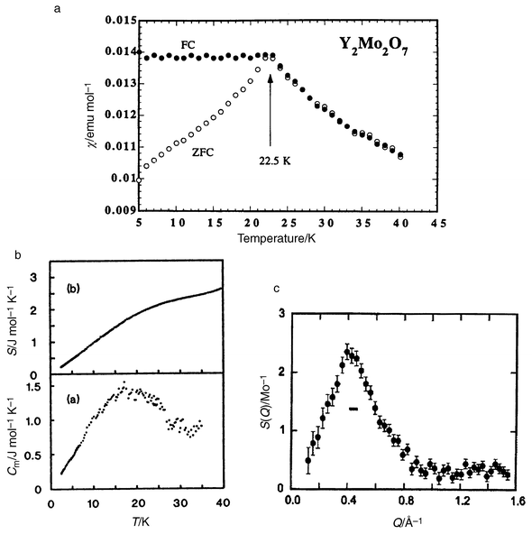
There are three possibilities, either the A-site or B-site occupied by magnetic ions or both sites so occupied. Beginning with B-site magnetic compounds, Y2Mo2O7 has been studied most extensively. Mo4+ is a 4d2, S = 1, ion. The Mo, 16c site, is octahedrally coordinated with six equal Mo–O distances but with a significant trigonal distortion such that the O–Mo–O angles are 99.5° and 80.5°.31 From the only detailed structural study to date, disorder such as Y ↔ Mo site interchange or disorder on either the O′ or O sites is at or below the level of detection by neutron powder diffraction.31 Very recently, a subtle type of disorder has been claimed to be associated with the Mo site but the details are not clear, nor is the connection with the physical properties.32 Y2Mo2O7 is an insulator or at least a semiconductor, and the magnetic properties are consistent with a high level of frustration, θc = −200 K and a phase transition occurs at 22 K. From the results shown in Fig. 17, which includes d.c. susceptibility,33 heat capacity34 and magnetic diffuse neutron scattering,35 this material can be characterized as a classical spin glass. There is FC–ZFC irreversibility below Tf, a linear contribution to the specific heat at low temperatures and no Bragg peaks in the neutron scattering. From the elastic neutron scattering, Fig. 17(c), a single broad peak is seen at Q ≅ 0.44 Å−1. This value of Q = 2π/d(110) where d(110) is the cube face diagonal √2 × 10.2 Å. This permits a four sublattice picture for the short range ordering as there are four tetrahedral corners (spins) along each of the zig-zag chains of corner sharing tetrahedra in the face diagonal direction, see Fig. 18. The correlation length derived from the width of the diffuse peak is ∼5 Å, indicating that the correlated domains extend over a volume no larger than the unit cell.
 |
| | Fig. 17
Magnetic, thermal and neutron scattering data for Y2Mo2O7: (a) susceptibility showing Tf = 22.5 K; (b) specific heat data showing a linear T dependence; (c) diffuse neutron scattering peaking near Q = 0.44 Å−1. The horizontal bar gives the resolution limit.33,34,35
| |
![A single chain of tetrahedra along [1 1 0] in the pyrochlore lattice.](/image/article/2001/JM/b003682j/b003682j-f18.gif) |
| | Fig. 18
A single chain of tetrahedra along [1 1 0] in the pyrochlore lattice.
| |
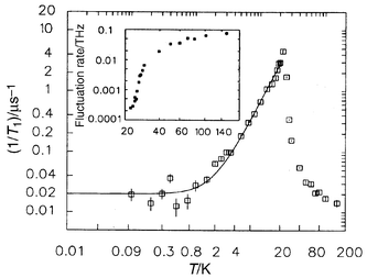
The spin dynamics have also been studied by both inelastic neutron scattering and muon spin relaxation.35,36 The picture which emerges is as follows: dynamic spin clustering or short range order sets in at temperatures as high as ∼200 K (the θc value), the spin fluctuation rate falls gradually to near Tf, below Tf there is a precipitative drop of two orders of magnitude to attain a very low but finite spin relaxation rate, 1/T1 of 0.02 µs at 0.09 K, Fig. 19. Basically, the spins are essentially frozen at the lowest temperatures, i.e. from both static and dynamic viewpoints, the material is a typical spin glass.
 |
| | Fig. 19
Muon spin relaxation (μSR) evidence for spin freezing in Y2Mo2O7.36
| |
This result is difficult to understand in the context of conventional, accepted ideas about spin glasses, wherein it is held that both frustration and positional disorder are necessary conditions. For example, in insulating antiferromagnets, spin glass behaviour is observed, normally, only in actual glasses (amorphous materials) or in crystalline compounds in which the magnetic sites have been diluted by diamagnetic ions to a concentration below the percolation limit. The percolation thresholds for the pyrochlore lattice are ∼40% for nn interactions and ∼25% for nnn interactions.37 The detectable defect levels in Y2Mo2O7 and most other pyrochlore materials are well below these limits.
There exist a number of other B-site magnetic pyrochlores which have received attention. The most unusual is Y2Mn2O7 which is a nearly ferromagnetic insulator with θc = 41 K but in one set of samples shows no true long range order according to heat capacity and neutron scattering.38 Some sort of phase transition is seen at 17 K. This gives an unusually high θc/Tc ratio of ∼3, as for typical ferromagnets this ratio is just slightly greater that 1. Nonetheless, in another set of samples a phase transition was seen in the heat capacity, suggesting long range order.39 More work is called for here to define the relationship between sample composition, preparative methods (high pressure methods are needed to stabilize the Mn4+state) and the physical properties.
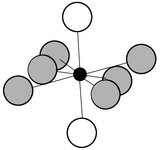
A-site only pyrochlores, especially the A2Ti2O7 phases, have attracted even more attention recently. As the local A-site coordination is very different than the B-site just described, some comments are in order before proceeding. The 16d site in the Fd3m pyrochlores is coordinated by six O(48f) ions and 2 O′(8b) ions, which might at first glance suggest that cubic symmetry would be a good approximation. However, the site is strongly distorted from 8-fold cubic. The site environment for Gd in Gd2Ti2O7 for example involves a puckered six membered ring of O(48f) ions with Gd–O distances of 2.55 Å and linear O′–Gd–O′ units orientated normal to the average plane of the puckered ring with very short Gd–O′ distances of 2.21 Å, see Fig. 20. This Gd–O distance is among the shortest, if not the shortest, such distance known in Gd–oxide chemistry and implies a strong axial interaction. It is thus much better to use the true symmetry, ![[3 with combining macron]](https://www.rsc.org/images/entities/char_0033_0304.gif) m
(D3d) when thinking about the single ion properties of the inhabitants of the A-site.
m
(D3d) when thinking about the single ion properties of the inhabitants of the A-site.
 |
| | Fig. 20
Eight-fold coordination at the A-site in A2B2O7 pyrochlore. The open circles are the O′(8b) atoms at a distance of ∼2.2 Å and the grey circles show the puckered six membered ring formed by the O(48f) atoms at a distance of ∼2.6 Å.
| |
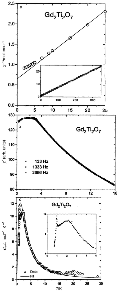
Thus, as crystal field effects and single ion properties will be important, it is best to begin with the case in which these issues have the minimum impact, i.e., Gd2Ti2O7 wherein the rare earth ion, Gd3+, 4f7, has the crystal field impervious 8S7/2 ground state which ought to approximate well to the Heisenberg and even the classical spin model. This material has been studied in detail.40 D.c. susceptibility results are shown in Fig. 21a and deviations from the Curie–Weiss law are obvious below ∼10 K which is near the Weiss temperature, θc = −9.6 K. Confirmation that θc is due entirely to AF exchange is provided by a companion study of (Gd0.02Y0.98)2Ti2O7 for which θc = −0.09 K. The a.c. susceptibility, Fig. 21b, shows no obvious maximum and essentially no frequency dependence with just a leveling off below 4 K. This indicates “cooperative paramagnetic” rather than spin glass behaviour. The magnetic component of the specific heat, Fig. 21c, shows several interesting features, first that magnetic contributions begin near 30 K and develop with decreasing temperature into a broad maximum just above 2 K followed by a sharp lambda spike at about 0.9 K. The broad peak can be modeled by assuming that the 8S7/2 multiplet is subject to an array of random magnetic fields. The lambda spike at 0.9 K indicates the onset of long range magnetic order, which has been confirmed recently by neutron diffraction.41 Detailed theoretical studies of the Heisenberg pyrochlore AF which include the effects of dipole–dipole interactions as well as exchange beyond n.n. indicate that these effects can destroy the high ground state degeneracy and permit ordering to occur.40
 |
| | Fig. 21
Magnetic and thermal data for Gd2Ti2O7:40 (a) d.c. susceptibility showing a deviation from the Curie–Weiss law below 10 K; (b) a.c. susceptibility showing cooperative paramagnetic behaviour; (c) specific heat data showing a broad anomaly due to short range order and a lambda spike due to long range order.
| |
For the remaining rare earth pyrochlores the crystal field cannot be neglected. The most striking example is Tm2Ti2O7 in which the crystal field creates a true singlet ground state, which is always a possibility for J = integral free ion states such as Tm3+, 3H6.44Table 5 collects the existing θc and Tc values for the RE2Ti2O7 compounds.
Table 5
Magnetic parameters for the RE2Ti2O7 pyrochlores17,40,42–49
| RE |
Free ion term |
θ
c/K |
T
cK |
|
Singlet ground state.
T-range 5 to 11 K.
|
| Gd |
8S7/2 |
−9.6, −11 |
0.97 |
| Gd0.02Y.98 |
8S7/2 |
−0.9 |
— |
| Tb |
7F6 |
−18.9 |
0.07< |
| Tb0.02Y0.98 |
7F6 |
−6.3 |
— |
| Dy |
6H15/2 |
−0.20, −0.65, −0.50 |
0.20< |
| Ho |
5I8 |
0.59, 2.8 |
0.05< |
| Er |
4I15/2 |
−15.9 |
1.25 |
| Tma |
3H6 |
35 |
— |
| Ybb |
2F7/2 |
0.59 |
0.214 |
As is evident, a wide range of θc values is observed, from −19 K (Tb) to slightly positive for Ho and Yb to large and positive for Tm. As exchange from both n.n. and further neighbours, dipolar and crystal field effects all contribute to the observed θc, great caution must be observed in the interpretation of this number. Dilution experiments, such as those reported for Gd and Tb, are useful in discriminating between the crystal field and the exchange + dipole contributions. The dipolar component can also be calculated. The crystal field contribution can be large and of either sign, as witness the large positive value, ∼35 K, for Tm2Ti2O7, which has in fact a non-magnetic singlet ground state and the large negative value for Tb2Ti2O7, −19 K.
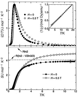
In any case note that three of the remaining materials, RE = Tb, Dy and Ho, show no sign of long range order into the 50 mK range (Dy to 200 mK). These have been discussed in terms of the “spin-ice” model described earlier. The clearest case for the ice analogy appears to be RE = Dy where the crystal field ground state is thought to be largely MJ = ±15/2 which means that it can be regarded as an effective S = 1/2 system. Specific heat data and the extracted residual entropy are shown to be in excellent agreement with Pauling’s prediction, S = R(ln 2 − 1/2 ln 3/2), Fig. 22.45 Ho2Ti2O7 is more unusual in that the Ising effective spins (the crystal field ground state appears to be largely MJ = ±8) might be coupled ferromagnetically.48 The strongest evidence for this comes from neutron scattering where enhanced intensity was seen at low temperatures (0.38 K) as the reciprocal space origin (0 0 0) was approached, i.e. small angle scattering (SANS).49 For reasons outlined above the slightly positive θc value is not conclusive for ferromagnetism. Very recently, the RE = Tb material, using the most detailed analysis of the crystal fields in RE titanates to date, was shown also to have an Ising-like magnetic doublet ground state composed primarily of MJ = ±5 and ±2.47 There is another doublet only 18 K above the ground state, observed by inelastic neutron scattering and specific heat, which complicates the analysis of the extracted entropy. The case of Tb2Ti2O7 presents a difficult problem for theory as the antiferromagnetic Ising spin system is not frustrated in the n.n. interaction limit and this issue has not been resolved. It is worth noting that although these “spin-ice” materials appear, superficially, to violate the Third Law, that is not necessarily the case as there must exist energetic barriers to relaxation to a minimum entropy ground state which are large compared to temperatures at which the phenomenon is exhibited.
 |
| | Fig. 22
Evidence for the “spin-ice” state in Dy2Ti2O7.45
| |
The results just described are for zero applied magnetic field. Application of a field tends in some cases to lift the ground state degeneracy and induce some form of ordering. In the case of Dy2Ti2O7, application of fields as small as 1.25 T results in the appearance of very sharp peaks in the heat capacity below 1 K, although it is not clear that these correspond to conventional long range order.45 In contrast, the heat capacity of Tb2Ti2O7 in fields as high as 6 T shows no such induced peaks, at least down to about 0.5 K.47 Further discussion of these experiments in applied fields lies outside of the scope of this review.
The final pyrochlore systems to be discussed are those with magnetic ions on both the 16d (A) and 16c (B) sites. Two systems which have been studied in some detail are the RE2Mn2O7 and RE2Mo2O7 materials.50,51 As mentioned in the discussion on Y2Mn2O7 earlier, the experimental situation has become clouded recently and this review will focus on the molybdates. These show a metal/insulator transition as a function of the RE element between RE = Gd, a correlated, ferromagnetic metal, and RE = Tb, a small activation energy semiconductor.51 The remaining heavy REs are also semiconducting. As mentioned, the metallic series members, RE = Nd, Sm and Gd are ferromagnetic or at least ferrimagnetic while the semiconductors, RE = Tb → Yb, do not show long range order. The θc values for the series RE = Tb → Yb, which were reported some time ago and should be viewed with considerable caution as the temperature range included was certainly too low, are much less negative than for Y2Mo2O7 which may indicate a net ferromagnetic RE ↔ Mo exchange interaction.51 This is evidence for RE ↔ Mo sublattice coupling. Tb2Mo2O7 has been studied most intensively. This material shows FC–ZFC irreversibilities near 25 K, suggestive of a spin glass type transition. As this is near Tf for Y2MoO7 and given that Tb2Ti2O7 shows no such effect, it can be inferred that the Mo(IV) sublattice drives this transition. Nonetheless, most of the signal detected in the d.c. susceptibility and the neutron scattering experiments must be due to Tb3+, J = 9, which also points to RE ↔ Mo coupling. Tf values for RE = Ho and Er are 22 K and 20 K respectively, very similar to RE = Tb.52
Tb2Mo2O7 shows only diffuse magnetic neutron scattering which is shown Fig. 23 compared with data for Tb2Ti2O7 and there are some similarities and differences.53 Recall that what is seen here is primarily the Tb contribution to the scattering, that for Mo would be more than an order of magnitude weaker (J = 9, Tb, versusS = 1, Mo, and the scattered intensity is proportional to the square of the angular momentum). The titanate shows broad peaks near Q = 1.1 Å−1 and 3.0 Å−1 while the molybdate has peaks at 1.1 and 2.1 Å−1 with an indication of a peak below 0.5 Å−1. The feature below 0.5 Å−1 is also seen in Y2Mo2O7, Fig. 17, and in Ho2Mo2O7.35,52 Thus, the periodicity of the diffuse scattering is different between the titanate and molybdate materials. Analysis of these results, Fig. 17(bottom), shows that the titanate data can be explained if the correlations extend only over n.n. distances in a single tetrahedron while the peaks at ∼0.4 and 2.1 Å−1, seen only in the Mo materials, require a longer correlation distance, at least to n.n.n. These observations are consistent with cooperative paramagnetism in Tb2Ti2O7 and a more complex spin glass like behaviour for the RE = Y and Tb phases.
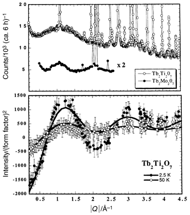 |
| | Fig. 23 Diffuse magnetic scattering for Tb2Mo2O7 and Tb2Ti2O7.53 | |
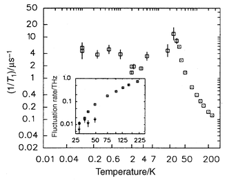
The spin dynamics for Tb2Mo2O7, studied by muon spin relaxation, indicate a behaviour somewhat similar to that for Y2Mo2O7 but with very significant differences. The spin fluctuation rate begins to slow well above Tf, ∼200 K, as in the RE = Y compound and 1/T1 peaks at Tf
(∼22 K) and then decreases but there is a weak minimum at ∼2 K and a recovery to a finite and relatively large value of 5 µs−1 down to the lowest temperature of 0.05 K, Fig. 24. The corresponding plateau value for Y2Mo2O7 is 250 times smaller, Fig. 19, but that for Tb2Ti2O7 is comparable, >1 µs−1.36 There is, thus, considerably more liquid-like character to the ground state for Tb2Mo2O7 and Tb2Ti2O7 than Y2Mo2O7 and this appears to be due to inherent disorder on the Tb sublattice.
 |
| | Fig. 24
μSR evidence for partial spin freezing in Tb2Mo2O7.36
| |
Spinels.
As already mentioned, the B site in the spinel structure, AB2O4, corresponds to 16d in Fd3m, and is therefore a “pyrochlore” sublattice. The B site in spinel is also octahedrally coordinated as is the B site in pyrochlore but the connectivity is very different, being edge-sharing in spinel but corner-sharing in pyrochlore. This means that the B–B distances, n.n. and beyond, are considerably shorter in spinels than in pyrochlores and the dominance of the n.n. interaction will be much diminished. As a result of these differences, spinel oxides usually exhibit LRO, but often, quite complex ground states. Two spinel materials will be discussed in this review, ZnFe2O4, and the family, Li1 + xMn2O4, where x = −1, 0 and +1.
ZnFe2O4 has been known for some time and, indeed, occurs as the mineral franklinite. While it is considered to be a normal spinel, there are many reports of partial inversion induced by preparative methods or even mechanical grinding. This is perhaps why basic data, such as a θc value for a well-ordered material, are scarce in the literature. For example, an early report claims θc = 0 K and a very much reduced Curie constant, C, for this compound.54 What is well established is that the material orders at the quite low temperature of 10 K into a ground state which can be described by ordering vector k = (0 0 1/2), i.e. a magnetic structure involving 32 spins, and, likely a non-collinear structure.55 Also, clear deviations from the Curie–Weiss law set in at temperatures as high as 300 K, which is consistent with a highly frustrated Fe3+ sublattice. Recent neutron scattering and μSR studies on a well-ordered sample have discovered the presence of significant diffuse magnetic scattering, detectable at temperatures as high as 100 K. This scattering has been ascribed to the presence of finite size, ∼30 Å, SRO regions of antiferromagnetic clusters, and the compound is said to exhibit “superantiferromagnetic” behaviour.56 As seen in Fig. 25, the integrated intensity of the diffuse peak grows sharply with a reduction in temperature down to Tc and then is diminished by the onset of LRO. Remarkably, the SRO component does not vanish, even at 4.2 K, well below Tc. These neutron results are mirrored in the μSR data which also show that the SRO component retains a dynamic character, relaxation rates of ∼>1 µs−1 at 4.2 K, values rather similar to those seen for the pyrochlore spin liquids. Thus, although LRO is established in this spinel, the ground state is not homogeneous, as LRO and dynamic SRO co-exist in the same temperature range below Tc.
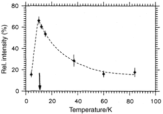 |
| | Fig. 25
Temperature dependence for the diffuse magnetic scattering fraction in ZnFe2O4. The ordering temperature is indicated.56
| |
Very similar behavior is seen in the system Li1 ± xMn2O4, another spinel better known as a battery cathode material. It is of course possible to add or subtract about one Li atom, either using soft chemistry or electrochemistry, to or from the cubic spinel LiMn2O4 without destroying the basic spinel lattice. This provides the opportunity to study the effect of changing the Mn oxidation state more or less continuously from Mn4+ to Mn3+ within the same environment. The structural relationships between the three materials which will be described here, x = −1 (λ-MnO2), x = 0 (LiMn2O4) and x = +1 (Li2Mn2O4), are shown in Fig. 26. The parent compound, LiMn2O4, is a well-ordered normal spinel with Li in the 8a tetrahedral sites. Removal of about one atom of Li leads to metastable λ-MnO2, which retains the Fd3m symmetry, and addition of one Li atom gives the tetragonal Li2Mn2O4
(I41/amd) wherein the Li atoms have migrated to the vacant 16c sites, i.e., the structure is now best described as ordered NaCl-type.
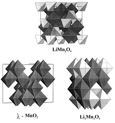 |
| | Fig. 26
The structural relations between LiMn2O4, λ-MnO2 and Li2Mn2O4.
| |
Beginning with LiMn2O4, there is a well-known structural phase transition below about 280 K which has been shown to be driven by a partial change ordering of the Jahn–Teller active Mn3+ ions. The symmetry of this low temperature form appears to be orthorhombic (Fddd) near the transition temperature but may become tetragonal (I41/amd) at lower temperatures, ∼100 K. The supercell is large in volume for either symmetry, a ≈ b ≈ 3ac, c ≈ ac for the orthorhombic description and a ≈ b ≈ 3/√2ac, c ≈ ac in the tetragonal setting.57,58 Some magnetic properties are listed in Table 6, along with those for the related phases. The |θc|/Tc ratio is near 5, suggesting frustration. The d.c. susceptibility shows an anomaly below about 65 K. Neutron diffraction, Fig. 27, shows that magnetic SRO appears at higher temperatures, actually up to 100 K but this is not shown in the figure, and that Bragg peaks are evident below 60 K. Note also that, like ZnFe2O4, the magnetic diffuse scattering co-exists with the LRO peaks down to 10 K. An estimate of the correlation length for the SRO gives a very small value, only on the order of the n.n. Mn–Mn distance, ∼3 Å, one tenth that for ZnFe2O4. Perhaps the most extraordinary finding is that the magnetic unit cell can be indexed with a vector, k = (1/2 1/2 1/4), based on the tetragonal supercell described above, i.e. there are at least 1152 spins within the magnetic unit cell! This is the current record for any GFAF material. More detailed studies including spin dynamics are clearly needed here.
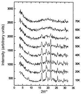 |
| | Fig. 27
Temperature dependence of the magnetic neutron diffraction for LiMn2O4.57
| |
Table 6
Magnetic parameters for λ-MnO2, LiMn2O4 and Li2Mn2O457,59,60
| Compound |
θ
c/K |
T
c/K |
|θc|/Tc |
Spins per magnetic cell |
| λ-MnO2 |
−100 |
32 |
3.1 |
128 |
| LiMn2O4 |
−300 |
60 |
5.0 |
1152 |
| Li2Mn2O4 |
∼−600 |
∼60 |
∼10 |
— |
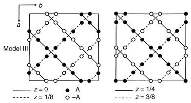
Although the frustration ratio is a modest 3 for λ-MnO2, the influence of frustration is evident.59 This material orders at 32 K with the appearance of Bragg peaks but again, diffuse scattering is clear up to nearly 2Tc, Fig. 28. Also, the “ordering” vector for the Bragg peaks and the diffuse peaks is actually different, a feature also found in ZnFe2O4. Additionally, the low temperature susceptibility shows considerable FC–ZFC irreversibility below Tc suggesting an inhomogeneous ground state and the probable co-existence of SRO and LRO. Some of this could be chemical in origin, as it is not possible to remove all of the Li, most samples retain from 3% to 10% Li and thus a corresponding concentration of Mn3+ co-exists with Mn4+. The ordering vector k = (1/2 1/2 1/2) implies a very large magnetic unit cell containing 128 spins. A not impossible but not necessarily unique magnetic structure has been deduced from the powder neutron diffraction data, Fig. 29, which shows three types of Mn tetrahedra, two have all 4 spins ferromagnetic but with spins antiparallel to each other and the other type has the classic two up two down pattern within the same tetrahedron. Structures similar to this have been reported much earlier for the normal spinels GeNi2O4 and GeCo2O4.61,62
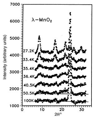 |
| | Fig. 28
Temperature dependence of the magnetic neutron diffraction for λ-MnO2.59
| |
 |
| | Fig. 29
A possible magnetic structure for λ-MnO2. The open and filled circles represent antiparallel spins.59
| |
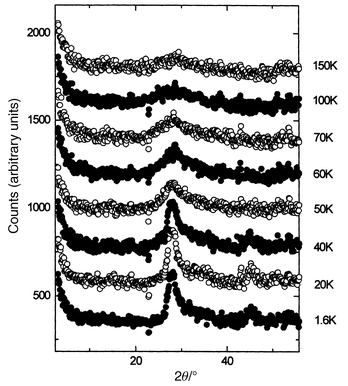
Perhaps the most remarkable compound in the set is Li2Mn2O4 which contains all Mn3+ and thus, thanks to a static Jahn–Teller distortion, has tetragonal symmetry.59 The intratetrahedral Mn–Mn distances are 2.805(2) and 3.098(2) Å. The bulk susceptibility shows a large negative θc, typical of Mn3+ oxides. The corresponding value for orthorhombic LiMnO2, the thermodynamically stable form at this composition, is θc = −1056 K.63 A clear transition occurs in the susceptibility below about 60 K. Again, this has been investigated by neutron diffraction, Fig. 30, and a broad SRO feature is evident even at 150 K. The strong reflection just below 30°
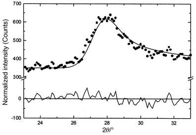
(2θ) narrows with decreasing temperature but retains a width well exceeding the resolution limit for this configuration and the shape is asymmetric even down to 1.6 K. The peak shape can be fitted very well to the Warren function which is appropriate to systems which are ordered in only two dimensions, Fig. 31. A two dimensional spin–spin correlation length derived from fits to the data of Fig. 31 shows a saturation at about 90 Å which is reached by about 40 K. The two reflections in Fig. 31, including the weaker one at about 45°
(2θ), can be indexed as (2 0) and (1 3) on a magnetic Kagome lattice with the √3 × √3 spin configuration, Fig. 12b. This remarkable observation seems to suggest that the magnetic correlations in this compound are confined to the Kagome layers of which the pyrochlore lattice can be constructed, Fig. 3. Thus, Li2Mn2O4 is, to our knowledge, the only example of a spinel oxide which never finds a true LRO ground state and for which the magnetic SRO is two dimensional, in spite of the fact that the pyrochlore magnetic sublattice is three dimensional. Much more work needs to be done here, including studies of the spin dynamics to characterize this unique material.
 |
| | Fig. 30
Temperature dependence of the magnetic neutron diffraction for Li2Mn2O4.55
| |
 |
| | Fig. 31
The (2 0) reflection for a √3 × √3 Kagome 2D structure in Li2Mn2O4. The solid line is a fit to the Warren function.55
| |
Other frustrated 3d lattices.
Two materials which have been discussed extensively in existing reviews,5,13 SrCr12 − xGaxO19
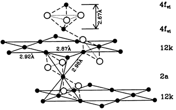
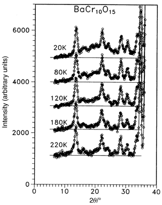
(SCGO) and Gd3Ga5O12 [gadolinium gallium garnet (GGG)], have distinctive frustrated lattices, Fig. 32 and 33. That for SCGO is best described as a pyrochlore slab and the Gd lattice in GGG consists of a 3d array of corner sharing triangles. Concerning SCGO it has been shown recently that the pyrochlore slabs, comprising sites 12k and 2a in Fig. 32, are magnetically decoupled from other parallel slabs due to the formation of a spin singlet dimer involving the 4fvi Cr sites.19 It is these sites which would provide the connectivity for the pyrochlore slabs. SCGO shows a large frustration ratio of ∼150 and undergoes a spin freezing at Tf ≈ 3.4 K for a sample with 90% coverage of the pyrochlore slab sites by Cr3+. The spin glass state is anomalous as the temperature coefficient of the specific heat is quadratic rather than linear. GGG also behaves like a spin glass in that a frequency peak appears in the a.c. susceptibility just below 0.2 K (θc = −2 K).64 Neutron scattering studies, Fig. 34, show that as the temperature is decreased, broad diffuse features grow in intensity but below 43 mK sharp peaks appear.65 These are incommensurate with the garnet lattice and the widths are broader than the resolution limit of the instrument, indicating short range ordering with a characteristic length of ∼100 Å. The data also show clearly that the spin ordered phase involves only a small fraction of the spins and the authors estimate that 85% of the spin volume remains in a liquid-like state. There is an interesting comparison between the garnets and the pyrochlores. In the RE gallium garnets, the Gd member, the S-ground state material, does not order while those REs with non-S state ions, Nd, Sm, Dy and Er, do order. For the pyrochlore titanates the Gd member does order but those REs with Ising single ion states, Tb, Dy and Ho, do not. This might be traceable to differences in the crystal field at the RE sites in the two structures and to the fact that dipolar interactions appear to dominate for the garnets while exchange is more important for the pyrochores. To conclude this section one relatively new lattice, which has received very little attention to date, will be mentioned. This is found in materials of composition AB10O15 where A = Sr or Ba and B = V or Cr. These compounds crystallize in an orthorhombic symmetry, Cmca, but the structure is close to that of corundum.66 In fact these compounds can be thought of as the result of “doping” either V2O3 or Cr2O3 with Ba or Sr. As the ions Ba2+ and Sr2+ are similar in radius to O2− they actually substitute in the close-packed oxide layers but in an ordered pattern, Fig. 35a. The cations in the close-packed layers then direct the occupation of the octahedral sites by the V or Cr ions and a rather different sublattice topology emerges than is found in the “parent” corundum structure, Fig. 35b. The B sublattice is seen to consist of B10 clusters of edge sharing tetrahedra which are connected in 3 dimensions to form a network. It should be pointed out that these are mixed valence oxides as the composition can be written A2+B2+2B3+8O15 and the distribution over the cation sites appears to be random although this is not known conclusively. There is thus an element of disorder on the B-site. Only d.c. susceptibility and neutron diffraction data are available to date but the results suggest that frustration plays an important role in the magnetism of these materials. This is best illustrated for BaCr10O15, Fig. 36, in which a spin glass like anomaly is seen at ∼25 K in the form of a broad maximum and FC–ZFC irreversibility. The Curie–Weiss law is not obeyed up to 300 K which suggests that θc is at least −300 K. Neutron diffraction data, Fig. 37, show only a very broad maximum which is evident at temperatures as high as 120 K and no LRO has been detected down to 5 K. In contrast, Cr2O3, with essentially the same moment density but a non-frustrated Cr lattice, orders at 308 K.67 From the width of the broad feature, a correlation length of only 3 Å is derived which corresponds to the Cr n.n. distance within a Cr10 cluster. More studies, especially on the spin dynamics, are needed to establish the nature of the ground state.
 |
| | Fig. 32
The SCGO magnetic sublattice showing the “pyrochore-slab” feature.19
| |
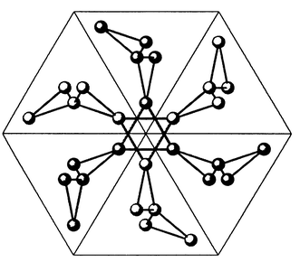 |
| | Fig. 33
The Gd3+ sublattice of corner sharing triangles in Gd3Ga5O12
(GGG).65
| |
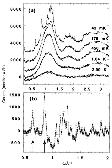 |
| | Fig. 34
Temperature dependence for the magnetic neutron diffraction in GGG.65
| |
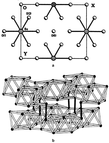 |
| | Fig. 35
The AB10O15 structure: (a) a hexagonal close packed (h.c.p.) AO8 layer; (b) the B-sublattice which consists of B10 clusters of edge sharing tetrahedra linked to form a 3D network.66
| |
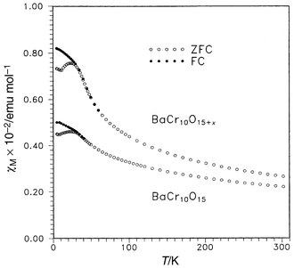 |
| | Fig. 36
The d.c. magnetic susceptibility for BaCr10O15 showing Tf ∼ 25 K.66
| |
 |
| | Fig. 37
Temperature dependence of the magnetic neutron diffraction for BaCr10O15. Diffuse scattering is seen even at 120 K.66
| |
S = 1/2 systems on a frustrated lattice
AF materials with S = 1/2 ions on a frustrated lattice have been of special and long term interest due to numerous theoretical predictions that such systems should exhibit spin liquid or even more exotic behaviour due in part to quantum spin fluctuations.68 In spite of intensive search efforts the number of serious contenders is small. A few of these, namely the effective spin 1/2 REs on a pyrochlore lattice, have been described earlier. Even in some of these cases there is ambiguity about the sign of the n.n. exchange, i.e., is it F or AF? In this final section are described a few materials in which genuine, as opposed to “effective”, S = 1/2 ions are involved.
Before proceeding to these it is worth a few words to discuss some cases which do not qualify to illustrate the experimental difficulties involved. When one thinks of potential S = 1/2 systems, ions with nd1 configurations come to mind, such as Ti3+, V4+, Nb4+, Mo5+, Re6+ and perhaps a few others. As well, low spin state ions with either nd5 or nd7 configurations, e.g. Ru3+
(t25) or Ni3+(t26e1) are also possible. For example the pyrochlore material Lu2V2O7 exists, with V4+ arranged, accommodatingly, on a pyrochlore lattice, but the compound is a ferromagnetic semiconductor.69 NaTiO2, an oxide with Ti3+ ordered on a triangular edge sharing lattice (in the layered, ordered NaCl motif to be discussed shortly), seems to have delocalized 3d1 electrons.70 Efforts to prepare pyrochlore oxides with Nb4+ on the B-site have failed in spite of the fact that RE2Zr2O7 and RE2Mo2O7 pyrochlores are well known. The closest approximation to this are the recently reported (RE,Ca)2Nb2O7 compounds with a 50% concentration of Nb4+on the B-site.71
Materials which do qualify adopt structures which can be regarded as variants of the ordered NaCl structure. The most extensively studied of these is LiNiO2, another compound better known perhaps from the electrochemical literature.72,73,74 In fact, non-stoichiometry and disorder plague this material and it is described more accurately as Li1 − xNi1 + xO2. The crystal structure is the rhombohedrally ordered NaCl type in which the Li+ and Ni3+ ions order in planes normal to the 〈1 1 1〉 direction in the NaCl structure and Fig. 38 shows the metal ion sublattices which consist of edge-sharing triangular nets stacked …ABCABC…. There is widespread agreement that Ni3+ is in the low spin state. Because of difficulties in synthesizing stoichiometric samples, early reports on the properties of “LiNiO2” involved claims of ferro and ferrimagnetism as well as various types of spin frozen ground states.72,73 There have been several studies on carefully characterized samples which show that for the range 0.02 > x > 0.0, the only feature in the d.c. susceptibility is a weak maximum around 9 K which shows FC–ZFC irreversibility.72–74 This has led some to conclude that the ground state for stoichiometric LiNiO2 is spin glass like.72 More recent results both from experiment and theory seem to indicate that the true situation may be more complex. For example, the specific heat has a T2.5 dependence at low temperatures, rather than the usual linear power law seen in most spin glasses.74 NMR results also seem to show that only 20% of the spins participate in the spin freezing below 9 K. It has been proposed that a quantum spin liquid with short range ferromagnetic correlations is the true ground state and that LRO is suppressed not by AF frustration but by frustration of “orbital ordering”.75
![The Ni3+ sublattice in LiNiO2. The Ni3+ and Li+ ions are ordered in planes normal to [1 1 1] in the cubic NaCl structure.72](/image/article/2001/JM/b003682j/b003682j-f38.gif) |
| | Fig. 38
The Ni3+ sublattice in LiNiO2. The Ni3+ and Li+ ions are ordered in planes normal to [1 1 1] in the cubic NaCl structure.72
| |
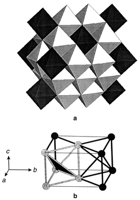
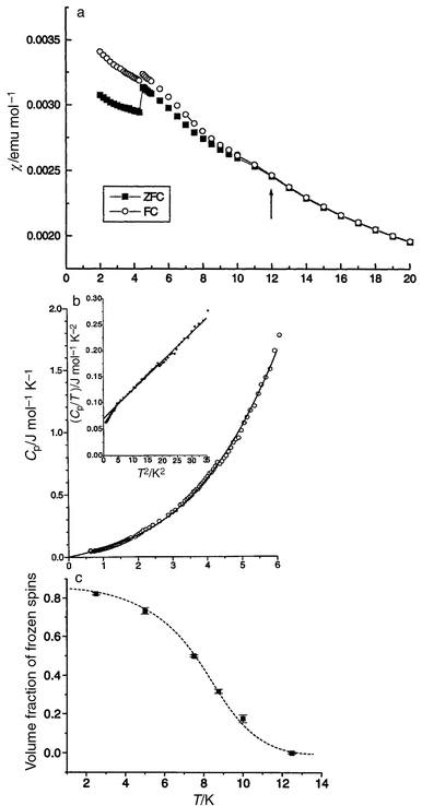
The final material to be discussed is Li4MgReO6 which is another ordered variant of the NaCl structure type.76 The magnetic species is Re6+ which is an S = 1/2 ion. Normally, Re6+ in oxides is not magnetic, recalling that ReO3 is a very good metal due to the delocalization of the Re d electrons. As will be shown, the Re ions in this material are sufficiently dilute that the 5d electrons remain localized. This compound crystallizes in monoclinic symmetry, C2/m, and the structure is shown in Fig. 39a. Because of the large difference in formal charges, the Re6+ ions order on sites distinct from those of the Li+ and Mg2+ ions which occupy randomly the remaining cation sites. The Re6+ sublattice which results is that of an array of face-sharing tetrahedra, Fig. 39b, which appears to be the first example of such a topology in a real material. The magnetic properties are consistent with frustration, θc = −166 K, but the frustration is manifest in a fairly subtle manner as there is no susceptibility maximum at low temperatures, only a FC–ZFC divergence setting in at about 12 K, Fig. 40a. The heat capacity shows a linear dependence at low temperatures, consistent with a spin glass state, Fig. 40b and the μSR confirms this as clear evidence for spin freezing below 12 K is evident and at least 90% of the spins are frozen by 2 K, Fig. 40c.
 |
| | Fig. 39
(a) Polyhedral representation for the structure of Li4MgReO6. The LiO and MgO octahedra are white and the ReO octahedra are black. (b) The Re sublattice which consists of face sharing tetrahedra.76
| |
 |
| | Fig. 40
Magnetic, thermal and μSR results for Li4MgReO6:76 (a) d.c. susceptibility showing a FC–FC divergence at 12 K. The anomaly at 5 K is due to an experimental time delay but reflects the presence of magnetic relaxation; (b) specific heat showing a linear T dependence; (c) the fraction of frozen spins as a function of temperature from μSR.
| |
Summary
An attempt has been made to convey at least a hint of the current state of knowledge in the area of GFAF materials. Emphasis has been placed on the growing set of compounds which exhibit exotic and poorly understood phenomena such as spin liquid, spin ice and spin glass behaviour. It has also been shown that many of these are oxides which, while of considerable interest in other areas, for example the battery cathode materials, are now attracting attention for their remarkable magnetic properties.
Acknowledgements
The author wishes to thank the students, postdoctorals and colleagues who have shared his enthusiasm for this fascinating subject over the past few years, in particular J. N. Reimers, M. Bieringer, C. Wiebe, C. Bridges, S. Dunsiger, N. P. Raju, R. Kremer, A. S. Wills, M. J. P. Gingras, B. D. Gaulin, A. Harrison, S. T. Bramwell, M. F. Collins, J. S. Gardner, G. Luke and R. Kiefl. He thanks A. S. Wills for a critical reading of the manuscript and C. Bridges for assistance with some of the figures. The Natural Sciences and Engineering Research Council of Canada has provided support through several Research grants and a Collaborative grant.
References
- G. Toulouse, Commun. Phys., 1977, 2, 115 Search PubMed.
- P. W. Anderson, Phys. Rev., 1956, 102, 1008 CrossRef CAS.
-
J. S. Smart, Effective Field Theories of Magnetism, W. B. Saunders, 1966. Search PubMed.
-
J. B. Goodenough and J. M. Longo, Crystallographic and Magnetic Properties of Perovskite and Perovskite-related Compounds, Landolt-Bornstein III/4a, Springer-Verlag, Berlin, 1970, p. 228. Search PubMed.
- P. Schiffer and A. P. Ramirez, Commun. Condens. Matter Phys., 1996, 10, 21 Search PubMed.
-
M. F. Collins, Magnetic Critical Scattering, Oxford University Press, Oxford, UK, 1989, pp. 16–19. Search PubMed.
- G. Ferey, R. DePape, M. Leblanc and J. Pannetier, Rev. Chim. Miner., 1986, 23, 474 Search PubMed.
- P. Lacorre, J. Phys., 1987, C20, L775 Search PubMed.
- J. Villain, Z. Phys. B, 1979, 33, 31 Search PubMed.
-
(a) J. N. Reimers, A. J. Berlinsky and A.-C. Shi, Phys. Rev. B, 1991, 43, 865 CrossRef CAS;
(b) R. Moessner and J. T. Chalker, Phys. Rev. Lett., 1998, 80, 2929 CrossRef CAS;
(c) R. Moessner and J. T. Chalker, Phys. Rev. B, 1998, 58, 12049 CrossRef CAS;
(d) J. N. Reimers, Phys. Rev. B, 1992, 45, 7287 CrossRef.
-
(a) P. W. Anderson, Mater. Res. Bull., 1973, 8, 153 CrossRef CAS;
(b) P. Fayelas and P. W. Anderson, Philos. Mag., 1974, 30, 423 Search PubMed.
-
L. Pauling, The Nature of the Chemical Bond, Cornell University Press, Ithaca, NY, 1960, pp. 464–469. Search PubMed.
- A. P. Ramirez, Ann. Rev. Mater. Sci., 1994, 24, 453 Search PubMed.
- S. T. Bramwell, S. G. Carling, C. J. Harding, K. D. M. Harris, B. M. Karuiki, L. Nixon and I. P. Parkin, J. Phys. Condens. Matter, 1996, 8, L123 CrossRef CAS.
-
(a) H. Serrano-Gonzales, S. T. Bramwell, K. D. M. Harris, B. M. Karuiki, L. Nixon, I. P. Parkin and C. Ritter, J. Appl. Phys., 1998, 83, 6314 CrossRef;
(b) H. Serrano-Gonzales, S. T. Bramwell, K. D. M. Harris, B. M. Karuiki, L. Nixon, I. P. Parkin and C. Ritter, Phys. Rev. B, 1999, 59, 14451 CrossRef.
- K. Kawamura and S. Miyashita, J. Phys. Soc. Jpn, 1985, 54, 3385 Search PubMed.
-
(a)
J. E. Greedan, Oxides with the trirutile and pyrochlore structures, Landolt-Bornstein III27g, Springer-Verlag, Berlin, 1992, pp. 87–123 Search PubMed;
(b) M. Saes, N. P. Raju and J. E. Greedan, J. Solid State Chem., 1998, 140, 7 CrossRef CAS.
- W.-M. Zhang, W. M. Saslow and M. Gabay amd M. Benaki, Phys. Rev. B, 1993, 48, 10204 CrossRef CAS.
- S.-H. Lee, C. Broholm, G. Aeppli, T. G. Perring, B. Hessen and A. Taylor, Phys. Rev. Lett., 1996, 76, 4424 CrossRef CAS.
- M. G. Townsend, G. Longworth and E. Roudaut, Phys. Rev. B, 1986, 33, 4919 CrossRef CAS.
- A. S. Wills and A. Harrison, J. Chem. Soc., Faraday Trans., 1996, 92, 2161 RSC.
- A. S. Wills, A. Harrison, C. Ritter and R. I. Smith, Phys. Rev. B, 2000, 61, 6156 CrossRef CAS.
- A. Harrison, A. S.wills and C. Ritter, Physica B, 1998, 241–243, 6156.
-
(a) T. Inami, S. Maegawa and M. Takano, J. Magn. Magn. Mater., 1998, 177–181, 752 CrossRef CAS;
(b) T. Inami.M. Nishiyama, S. Maegawa and Y. Oka, Phys. Rev. B, 2000, 61, 12181 CrossRef.
-
(a) A. B. Harris, C. Kallin and A. J. Berlinsky, Phys. Rev. B, 1992, 45, 2899 CrossRef;
(b) J. T. Chalker, P. C. W. Holdsworth and E. F. Shender, Phys Rev. Lett., 1992, 65, 855 CrossRef CAS;
(c) J. N. Reimers and A. J. Berlinsky, Phys. Rev. B, 1993, 48, 9539 CrossRef CAS.
- S.-H. Lee, C. Broholm, M. F. Collins, L. Heller, A. P. Ramirez, Ch. Kloc, E. Bucher, R. W. Erwin and N. Lacevic, Phys. Rev. B, 1997, 56, 8091 CrossRef CAS.
- A. S. Wills, A. Harrison, S. A. M. Mentink, T. E. Mason and Z. Tun, Europhys. Lett., 1998, 42, 325 Search PubMed.
- G. S. Oakley, D. Visser, J. Frunzke, K. H. Andersen, A. S. Wills and A. Harrison, Physica B, 1999, 267–268, 142 CrossRef CAS.
- J. N. Reimers, Phys. Rev. B, 1992, 46, 193 CrossRef CAS.
- G. Oakley, S. Pouget, A. Harrison, J. Frunzke and D. Visser, Physica B, 1999, 267–268, 145 CrossRef CAS.
- J. N. Reimers and J. E. Greedan, J. Solid State Chem., 1988, 72, 390 CrossRef CAS.
-
C. H. Booth, J. S. Gardner and G. Kwei, Phys. Rev. B, 2000, in press. Search PubMed.
-
(a) J. E. Greedan, M. Sato, Xu Yan and F. S. Razavi, Solid State Commun., 1986, 59, 895 CrossRef CAS;
(b) M. J. P. Gingras, C. V. Stager, N. P. Raju, B. D. Gaulin and J. E. Greedan, Phys. Rev. Lett., 1997, 78, 947 CrossRef CAS.
- N. P. Raju, E. Gmelin and R. K. Kremer, Phys. Rev. B, 1992, 46, 5405 CrossRef CAS.
- J. S. Gardner, B. D. Gaulin, S.-H. Lee, C. Broholm, N. P. Raju and J. E. Greedan, Phys. Rev. Lett., 1999, 83, 211 CrossRef CAS.
- S. R. Dunsiger et al., Phys. Rev. B, 1996, 54, 9019 CrossRef.
-
M. Gingras, personal communication..
- J. N. Reimers, J. E. Greedan, R. K. Kremer, E. Gmelin and M. A. Subramanian, Phys. Rev. B, 1991, 43, 387.
- Y. Shimakawa, Y. Kubo, N. Hamada, J. D. Jorgensen, Z. Hu, S. Short, M. Nohara and H. Takagi, Phys. Rev. B, 1999, 59, 1249 CrossRef CAS.
- N. P. Raju, M. Dion, M. J. P. Gingras, T. E. Mason and J. E. Greedan, Phys. Rev. B, 1999, 59, 14489 CrossRef CAS.
-
M. J. Harris and S. T. Bramwell, personal communication..
- M. P. Zinkin, M. J. Harris, Z. Tun, R. A. Cowley and B. M. Wanklyn, J. Phys. Condens. Matter, 1996, 8, 193 CrossRef CAS.
- S. T. Bramwell, M. N. Field, M. J. Harris and I. P. Parkin, J. Phys. Condens. Matter, 2000, 12, 483 CrossRef CAS.
- H. W. J. Blote, R. F. Wielinga and W. J. Huiskamp, Physica, 1969, 43, 549 Search PubMed.
- A. P. Ramirez, A. Hayashi, R. J. Cava, R. Siddharthan and B. S. Shastry, Nature, 1999, 399, 333 CrossRef CAS.
- J. S. Gardner, B. D. Gaulin, S.-H. Lee, C. Broholm, N. P. Raju and J. E. Greedan, Phys. Rev. Lett., 1999, 82, 1012 CrossRef CAS.
-
L. J. Chang, B. C. Den Hertog, M. Faucher, J. S. Gardner, B. D. Gaulin, M. J. P. Gingras, J. E. Greedan, N. P. Raju and T. E. Mason, Phys Rev. B, 2000, in press. Search PubMed.
- S. T. Bramwell and M. J. Harris, J. Phys. Condens. Matter, 1998, 10, L215 CrossRef CAS.
- M. J. Harris, S. T. Bramwell, T. Zeiske, D. F. McMorrow and P. J. C. King, J. Magn. Magn. Mater., 1998, 177–181, 757 CAS.
- J. E. Greedan, N. P. Raju, A. Maignan, Ch. Simon, J. S. Pedersen, A. N. Niraimathi, E. Gmelin and M. A. Subramanian, Phys. Rev. B, 1996, 54, 7189 CrossRef CAS.
-
(a) M. Sato, Xu Yan and J. E. Greedan, Z. Anorg. Allg. Chem., 1986, 540–541, 177 CrossRef CAS;
(b) J. E. Greedan, M. Sato, N. Ali and W. R. Datars, J. Solid State Chem., 1987, 68, 300 CAS;
(c) J. E. Greedan, J. N. Reimers, C. V. Stager and S. L. Penny, Phys. Rev. B, 1991, 43, 5682 CrossRef CAS.
-
J. E. Greedan, unpublished work..
- B. D. Gaulin, J. S. Gardner, S. R. Dunsiger, Z. Tun, M. D. Lumsden, R. F. Kiefl, N. P. Raju, J. M. Reimers and J. E. Greedan, Physica B, 1998, 241–243, 511.
- F. K. Lotgering, J. Phys. Chem. Solids, 1966, 27, 139 CrossRef CAS.
- U. Konig, E. F. Bertaut, Y. Gros, M. Mitrikov and G. Chol, Solid State Commun., 1970, 8, 759 CrossRef.
- W. Schiessl, W. Potzel, H. Karzel, M. Steiner, G. M. Kalvius, A. Martin, M. K. Krause, I. Halgvy, J. Gal, W. Schäfer, G. Will, M. Hillberg and R. Wäppling, Phys. Rev. B, 1996, 53, 9143 CrossRef CAS.
- A. S. Wills, N. P. Raju and J. E. Greedan, Chem. Mater., 1999, 11, 1510 CrossRef CAS.
- J. Rodriguez-Carvajal, G. Rousse, C. Masquelier and M. Hervieu, Phys. Rev. Lett., 1998, 81, 4660 CrossRef CAS.
- J. E. Greedan, N. P. Raju, A. S. Wills, C. Morin and S. M. Shaw, Chem. Mater., 1998, 10, 3058 CrossRef CAS.
- A. S. Wills, N. P. Raju, C. Morin and J. E.Greedan, Chem. Mater., 1999, 11, 1936 CrossRef CAS.
- E. F. Bertaut, V. V. Qui, R. Pauthenet and A. Murasik, J. Phys., 1964, 25, 516 Search PubMed.
- R. Plumier, C.R. Acad. Sci. Paris, 1967, 264, 278 Search PubMed.
- J. E. Greedan, N. P. Raju and I. J. Davidson, J. Solid State Chem., 1997, 128, 209 CrossRef CAS.
- A. P. Ramirez, D. A. Huse, P. L. Gammel, U. Yaron, D. J. Bishop and A. J. Valentino, Phys. Rev. Lett., 1995, 74, 2374 CrossRef.
- O. A. Petrenko, C. Ritter, M. Yethiraj and D. McK Paul, Phys. Rev. Lett., 1998, 80, 4570 CrossRef CAS.
- G. Liu and J. E. Greedan, J. Solid State Chem., 1996, 122, 416 CrossRef CAS.
- S. Foner, J. Appl. Phys. Suppl., 1961, 32, 635 Search PubMed.
- B. Canals and C. Lacroix, Phys. Rev. Lett., 1998, 80, 2933 CrossRef CAS.
- G. V. Bazuev, O. V. Makarova and G. P. Shveikin, Russ. J. Inorg. Chem., 1983, 28, 1088 Search PubMed.
- S. J. Clarke, A. J. fowkes, A. Harrison, R. M. Ibberson and M. J. Rosseinsky, Chem. Mater., 1998, 10, 372 CrossRef CAS.
-
(a) S. Ya Istomin, O. G. D'Yachenko, E. V. Antipov and G. Svensson, Mater. Res. Bull., 1997, 32, 421 CrossRef CAS;
(b) S. Ya Istomin, O. G. D'Yachenko, E. V. Antipov, G. Svensson and B. Lundquist, Mater. Res. Bull., 1998, 33, 1251 CrossRef CAS.
- J. N. Reimers, J. R. Dahn, J. E. Greedan, C. V. Stager, G. Liu, I. J. Davidson and U. von Sacken, J. Solid State Chem., 1993, 102, 542 CrossRef CAS.
- A.-L. Barra, G. Chouteau, A. Stepanov, A. Rougier and C. Delmas, Eur. Phys. J. B, 1999, 7, 551 CrossRef CAS.
- Y. Kitaoka, T. Kobayashi, A. Koda, H. Wakabayashi, Y. Niino, H. Yamakage, S. Taguchi, K. Amaya, K. Yamaura, M. Takano, A. Hirano and R. Kanno, J. Phys. Soc. Jpn., 1998, 67, 3703 Search PubMed.
- L. F. Feiner, A. M. Oles and J. Zaanen, Phys. Rev. Lett., 1997, 78, 2799 CrossRef CAS.
-
M. Bieringer, N. P. Raju, G. Luke and J. E. Greedan, Phys. Rev. B, 2000, in press. Search PubMed.
Footnote |
| † Basis of a presentation given at Materials Discussion No. 3, 26–29 September, 2000, University of Cambridge, UK. |
|
| This journal is © The Royal Society of Chemistry 2001 |
Click here to see how this site uses Cookies. View our privacy policy here. 


![The pyrochlore lattice as a stacking of Kagome layers. (top) View normal to the stacking direction. (bottom) View along the stacking direction [1 1 1] of the cubic pyrochlore cell.](/image/article/2001/JM/b003682j/b003682j-f3.gif)


![[3 with combining macron]](https://www.rsc.org/images/entities/char_0033_0304.gif) , for A = Cs and Rb or distorted to monoclinic, C2/m, for A = K or Na. The M sublattice is perfect edge shared equilateral triangular (ET) for the trigonal form and isosceles triangular (IT) for the monoclinic alums with for example angles of 64.60, 57.70 and 57.70° for KFe(SO4)2. The layer stacking is …AAA…, so 3d interlayer frustration is not an issue. Relevant magnetic data are listed in Table 2.
, for A = Cs and Rb or distorted to monoclinic, C2/m, for A = K or Na. The M sublattice is perfect edge shared equilateral triangular (ET) for the trigonal form and isosceles triangular (IT) for the monoclinic alums with for example angles of 64.60, 57.70 and 57.70° for KFe(SO4)2. The layer stacking is …AAA…, so 3d interlayer frustration is not an issue. Relevant magnetic data are listed in Table 2.


![The sine wave modulated magnetic structure on the isosceles triangular lattice of monoclinic KFe(SO4)2. The spins lie along the [1 1 1/2] and [−1 −1 −1/2] directions and (+ or −) and the amplitude is modulated along [1 −1 0].15](/image/article/2001/JM/b003682j/b003682j-f8.gif)


![[3 with combining macron]](https://www.rsc.org/images/entities/char_0033_0304.gif) m, is shown in Fig. 11. The Kagome layers, Fig. 11(top), consist of corner sharing FeO6 octahedra in a distinctive pattern involving triangular and hexagonal “holes”also found in the pyrochlore structure. While the FeO octahedra are clearly puckered, the Fe ions form a perfectly planar Kagome net. The layer stacking sequence is …ABCABC… along the c-axis and the FeO layers are well separated, 6 Å, by sulfate, hydroxide and A-site ions, Fig. 11(bottom).
m, is shown in Fig. 11. The Kagome layers, Fig. 11(top), consist of corner sharing FeO6 octahedra in a distinctive pattern involving triangular and hexagonal “holes”also found in the pyrochlore structure. While the FeO octahedra are clearly puckered, the Fe ions form a perfectly planar Kagome net. The layer stacking sequence is …ABCABC… along the c-axis and the FeO layers are well separated, 6 Å, by sulfate, hydroxide and A-site ions, Fig. 11(bottom).


![[3 with combining macron]](https://www.rsc.org/images/entities/char_0033_0304.gif) m is a subgroup of Fd3m.
m is a subgroup of Fd3m.![One layer of corner sharing octahedra of composition BO3 normal to the [1 1 1] direction in the A2B2O7 pyrochlore structure.](/image/article/2001/JM/b003682j/b003682j-f16.gif)

![A single chain of tetrahedra along [1 1 0] in the pyrochlore lattice.](/image/article/2001/JM/b003682j/b003682j-f18.gif)

![[3 with combining macron]](https://www.rsc.org/images/entities/char_0033_0304.gif) m
(D3d) when thinking about the single ion properties of the inhabitants of the A-site.
m
(D3d) when thinking about the single ion properties of the inhabitants of the A-site.


![The Ni3+ sublattice in LiNiO2. The Ni3+ and Li+ ions are ordered in planes normal to [1 1 1] in the cubic NaCl structure.72](/image/article/2001/JM/b003682j/b003682j-f38.gif)


