DOI:
10.1039/B003243N
(Feature Article)
J. Mater. Chem., 2001,
11, 29-36
The route to CMR manganites: what about charge
ordering and phase separation?†
Received 25th April 2000, Accepted 12th June 2000
First published on UnassignedUnassigned6th October 2000
Abstract
The CMR manganites Ln1 − xAxMnO3
with the perovskite structure form a very important family of magnetic oxides,
studied for their fascinating colossal magnetotransport properties. In this
review, we discuss two phenomena, charge ordering and phase separation, which
are crucial for the appearance of CMR in these oxides. We propose a new route
to CMR, based on the Mn-site doping of these materials by other cations,
such as Cr, Co, Ni and Ru.
The discovery of magnetoresistance properties in manganese oxides with
the perovskite structure has allowed new features related to charge ordering
and electronic phase separation to be evidenced and discussed. The properties
of charge ordering in perovskite manganites Ln1 − xAxMnO3
(Ln = lanthanide,
A = Ca, Sr) were established a long time ago,1,2 long before the discovery of colossal magnetoresistance (CMR)
effects3–5 in these oxides.In these systems, the charge ordered (CO) state is insulating
and either antiferromagnetic or paramagnetic, but plays a very important role
in the CMR effect: it can be melted into a ferromagnetic (FM) metallic
state by application of a magnetic field. This ability to generate a FM metallic
state is explained by a double exchange (DE) mechanism,6
but the origin of the melting of the CO state under a magnetic field, the
relationships between this transformation and the structure and chemical bonding
are still matters of discussion. In a similar way, the behavior of orbital
ordering and its relation with charge ordering are, so far, not completely
understood.
The results obtained by numerous authors clearly show that the CMR effect
results from the coexistence of two competing phases, a ferromagnetic metallic (FMM)
phase with an antiferromagnetic insulating phase (AFMI).7 It has been proposed that the intriguing properties
of CMR manganites are due to electronic phase separation, involving the coexistence
of regions of different carrier concentrations within the same crystal.8 Such a pure electronic phase segregation is difficult
to explain over a large length scale. In fact, it will be shown further that
this phase separation originates from the coexistence of different structures
within the same crystal, in agreement with the numerous structural transitions
observed in these oxides.
In this review, we discuss the main features which govern the charge and
orbital ordering in manganites in connection with their magnetoresistive properties,
and we describe the different results which evidence phase separation in these
systems.
Structural evidence for charge ordering
The first evidence for the collapse of a charge ordered state under a magnetic
field was shown for Pr1/2Sr1/2MnO3.9 Unfortunately, subsequent structural investigations,
coupling neutron diffraction and electron microscopy10
did not confirm the existence of a CO state for this phase at low temperature.
Thus, this phenomenon, although it is of particular interest, cannot be attributed
to the collapse of charge ordering, but rather to a structural transition
of a different nature, implying a transition from A-type AFM10,11
to FMM upon the application of a magnetic field. In contrast, CO has been
observed by structural techniques in several CE-type AFM half doped manganites
Ln0.5Ca0.5MnO3 with Ln = La,
Nd, Pr, Sm.12–16
In the CE-type AFM structure, zig-zag FM chains of Mn3+/Mn4+
are AFM coupled with their nearest neighboring chains. In these CO oxides,
a doubling of one cell parameter, a, when cooling the material below TCO
is observed. This behavior corresponds to a 1 ∶ 1 ordering
of the Mn3+ and Mn4+ species. From the TEM
observations, it appears probable that the CO appears as Mn3+
and Mn4+ stripes which alternate along a. In fact,
the CO is not limited to the particular composition Ln0.5Ca0.5MnO3.
Charge ordered stripes have been evidenced by lattice imaging in electron
microscopy for x > 0.50 in La1 − xCaxMnO317 and for 0.4 ≤ x ≤ 0.75
in Sm1 − xCaxMnO3.15 Such phenomena are illustrated by the lattice images
of the “SmCa” manganites recorded at 92 K, i.e.
below TCO
(Fig. 1).
For particular x values, x = 3/4,
2/3 and 1/2, a system of fringes spaced by 22 (Fig. 1a),
16.5 (Fig. 1b) and 11 Å
(Fig. 1c) respectively, is observed, corresponding
to a quadrupling, a tripling and a doubling of the a = ap√2
parameter, in agreement with the corresponding electron diffraction patterns.
These results can be easily interpreted as the alternation along a
of one Mn3+ stripe, with three (Fig. 2a),
two (Fig. 2b) and one (Fig. 2c) Mn4+ stripes.
For intermediate x values, the situation is more complex, as exemplified
by two lattice images (Fig. 3b,c)
recorded for x = 0.55, where it is shown that
the ordering of the stripes either takes place in a short range manner (Fig. 3b), or in a regular long range sequence,
but with a more complex “periodicity” close to 7ap√2.
In fact, whatever the value of x in the range from 0.40 to 0.75,
a long range ordering of the Mn3+ and Mn4+
stripes exists, which can be either commensurate for particular x
values, or incommensurate for intermediate x values. Such a long
range ordering of the stripes can thus be characterized by the wave q
vector, which is remarkably found to be roughly equal to the 1 − x
value, i.e.q ≈ 1 − x
at 92 K, so that the superstructure along a for particular x
values is given by a ≈ (1/q)ap√2.![[010] ED
patterns and [010] lattice images recorded at 92 K for Sm1 − xCaxMnO3 with (a)
x = 3/4, (b)
x = 2/3
and (c)
x = 1/2.](/image/article/2001/JM/b003243n/b003243n-f1.gif) |
| | Fig. 1 [010] ED
patterns and [010] lattice images recorded at 92 K for Sm1 − xCaxMnO3 with (a)
x = 3/4, (b)
x = 2/3
and (c)
x = 1/2. | |
 |
| | Fig. 2 Examples of structural
models for Sm1 − xCaxMnO3
with (a)
q = 3/4, (b)
q = 2/3
and (c)
q = 1/2. | |
![Sm0.45Ca0.55MnO3
at 92 K: (a)
[010] pattern and [010]
lattice images of different areas of the corresponding crystallite. They exemplify (b)
short range ordering and (c) long range ordering.](/image/article/2001/JM/b003243n/b003243n-f3.gif) |
| | Fig. 3 Sm0.45Ca0.55MnO3
at 92 K: (a)
[010] pattern and [010]
lattice images of different areas of the corresponding crystallite. They exemplify (b)
short range ordering and (c) long range ordering. | |
The transition from the AFM charge ordered state to the paramagnetic state
is clearly evidenced by the evolution of the q value versus
temperature, as shown for several x compositions (Fig. 4).
After the low temperature plateau which characterizes the CO, the q
vector decreases abruptly as T increases, corresponding to the disappearance
of charge ordering above TCO. Note that the TCO
value deduced from the structural evolution is closely connected with the Tpeak
value observed on the magnetization curves of these oxides (Fig. 5), i.e.Tpeak ≈ TCO, showing that charge
ordering plays a prominent role in the appearance of the AFM state at low
temperature. This is the reason why many authors assign the M(T)
peak of the manganites to charge ordering, but without any crystallographic
proof of its existence.
 |
| | Fig. 4 Evolution of qversusT
for the different Sm1 − xCaxMnO3
samples with 0.40 ≤ x ≤ 0.75. For the x = 0.50
sample, arrows indicate two particular temperatures: ↑, temperature at
which superlattice spot appears on cooling (TCO); ↓,
temperature at which the q value remains constant (q = qmax). | |
 |
| | Fig. 5 T dependence
of the magnetization of the series of Sm1 − xCaxMnO3
samples, where Tpeak indicates the temperature of the
maximum magnetization value. | |
The effect of A cation size upon CO: influence
on CMR properties
The strong influence of the size of the A-site cations upon charge
ordering has been evidenced by several authors.18–20
This phenomenon is easily explained by the fact that the Mn–O–Mn
bond angle is significantly affected by the size of the A cations and, consequently,
the eg band width is strongly dependent on 〈rA〉.
A comparison of the magnetic phase diagrams recently established for four
Ln1 − xAxMnO3
systems, with Ln = Pr, Sm and A = Ca,
Sr,21 illustrates the important role of the
A cation size upon CO and, consequently, upon the magnetotransport properties
of these oxides. The “SmCa”
(Fig. 6a)
and “PrCa”
(Fig. 6b)
manganites, which are characterized by smaller 〈rA〉
values, exhibit both CO domains for a wide range of compositions, from x = 0.40
to 0.80 for Sm and from 0.34 to 0.85 for Pr; their regions coincide in both
cases with a large AFMI region. In both systems, TCO goes
through a maximum for x = 0.60. The “SmCa”
system exhibits maximum TCO values significantly larger
than those of the “PrCa” system, showing that TCO
is reinforced as 〈rA〉 decreases when replacing
praseodymium by samarium. Such an increase of TCO by decreasing 〈rA〉
was also shown for the solid solution Pr0.5Sr0.5 − xCaxMnO3,20 for which TCO increases from
180 K for x = 0.25 to 250 K for x = 0.50.
Note that the charge ordering temperature may be significantly different from
the Néel temperature, as shown for the “PrCa system”, for
which TN < TCO
(Fig. 6b). When 〈rA〉
increases, the CO is rapidly destabilized, as shown for the "SmSr" manganites (Fig. 6c), for which the CO domain is reduced
to x = 0.4–0.66, and finally disappears
for higher 〈rA〉 values, as illustrated by the “PrSr”
system (Fig. 6d), for which
no CO was evidenced. Note also that the dramatic influence of 〈rA〉
upon TCO is confirmed: the “SmSr” manganites
show TCO values ranging from 130 to 200 K (Fig. 6c), to be compared to the “PrCa”
system (Fig. 6d), whose smaller 〈rA〉
values allow TCO values up to 260 K to be reached. |
| | Fig. 6 Magnetic phase diagrams
for the Sm1 − xCaxMnO3
(a),
Pr1 − xCaxMnO3
(b),
Sm1 − xSrxMnO3
(c)
and Pr1 − xSrxMnO3
(d)
series. The gray symbols and lines are for the magnetization values at 4.2 K (right y
axis). Black symbols: (●)
TC, (■)
TCO, (▲)
TN. FM: ferromagnet, M for metal and I for insulator; AFM: antiferromagnet;
CO: charge ordered; CG: cluster glass. The dashed areas are for intermediate
regions. The CMR compositions are delimited by arrows in the upper parts. | |
It is also remarkable, upon comparing these four diagrams, that the reduction
of the CO region, which results from the increase of 〈rA〉
(Ca → Sr),
takes place to the benefit of the ferromagnetic domain, which expands from x ≈ 0.04–0.30
for the Ca systems (Fig. 6a,b)
to x ≈ 0.1–0.50 for the Sr system (Fig. 6c,d), TC increasing
with 〈rA〉 and the FMM state replacing progressively
the FMI state as 〈rA〉 increases. Another point
concerns the disappearance of the CO state on the Mn4+ rich
side (x > 0.50) for higher 〈rA〉
values, i.e. in the Sr systems, for which an AFMI state without CO
extends over a wide compositional range, from 0.60 to 0.9 for “SmSr”
(Fig. 6c) and for 0.5 to 0.90 for “PrSr”
(Fig. 6d). In contrast, for smaller 〈rA〉
values, the CO state persists over a large compositional range in the Mn4+
region, being replaced by a short range charge ordering around x ≈ 0.8,
leading finally to a cluster glass (CG)22
for x ≥ 0.9 (see Fig. 6a,b)
in which ferromagnetic clusters coexist within the AFM matrix.
This modification of the CO state versus
〈rA〉
has a great impact on the magnetotransport properties of the manganites. The
resistivity of the manganites is indeed influenced by charge ordering, as
illustrated by the ρ(T) curves of several
Sm1 − xCaxMnO3
oxides (Fig. 7). For the oxides
corresponding to 0.40 ≤ x ≤ 0.85, a
transition from a semi-metallic behavior or semi-conducting state
to an insulating state as T decreases is indeed observed. All the
curves (Fig. 7) show a resistivity
jump at a temperature TR, which coincides in fact with
the peak temperature on the M(T) curves (Fig. 5), and corresponds, in fact, to TCO.
Clearly, at low temperature, below TCO, the antiferromagnetic
insulating state is stabilized.
 |
| | Fig. 7 T dependence
of the resistivity for the Sm1 − xCaxMnO3
samples with 0.40 ≤ x ≤ 0.85 (x
values are labelled on the graph). The arrow indicates TR. | |
From the viewpoint of the CMR effect, the CO state opposes the appearance
of a ferromagnetic metallic state, since it is highly insulating, but allows
the obtention of the highest resistance ratio. Its destruction, by applying
a magnetic field in order to get the FMM state, allows resistivity jumps of
several orders of magnitude to be reached. Thus, in order to produce a CMR
effect, the manganite should either exhibit a paramagnetic insulating to ferromagnetic
metallic transition, or at least present a metastability of its insulating
charge ordered state, which can be destroyed by a magnetic field. This viewpoint
is strongly supported by comparison of the magnetic phase diagrams in Fig. 6. CMR appears in FMM regions, as shown
for “SmSr”
(Fig. 6c)
and “PrSr”
(Fig. 6d),
and can extend over the CO region. For small A cations, “SmCa”
(Fig. 6a) and “PrCa”
(Fig. 6b) systems, CMR is obtained in spite
of the absence of a ferromagnetic metallic state (FMM). CMR appears
in the electron doped regions at the boundary between the CO and the CG regions.
Moreover, in the hole doped region, a CMR effect can also be obtained at the
boundary between the FMI and CO regions, for the PrCa system (Fig. 6b). The compositional range where
the CMR appears corresponds, then, to the regions where CO is either not well
established or, in any case, not yet very stable. For this reason, the CMR
compositional ranges that are obtained for the small A cations are rather
narrow. Nevertheless, the CMR effects are spectacular, as exemplified for
the electron doped manganite22 Sm0.15Ca0.85MnO3
(Fig. 8a), which exhibits a resistance ratio
of 102 at 80 K under 7 T and for the oxide Pr0.7Ca0.3MnO3
(Fig. 8b), for which a resistance ratio
of 3 × 10² at 80 K under 7 T was
reached. In contrast, for large A cations, “SmSr”
(Fig. 6c) and “PrSr”
(Fig. 6d), the CMR effect appears only in
the hole doped region, due to the fact that the metastable charge ordered
state has disappeared in the electron rich region close to SrMnO3,
and is replaced by a very stable AFMI state. Then, the CMR effect covers a
rather wide composition range involving the adjacent CO and FMM and even FMI
domains as shown for the “SmSr” system (Fig. 6c),
for which TCO is smaller than 200 K, so that CO
state is certainly more metastable. For the largest 〈rA〉
values, “PrSr”, the CMR effect also extends over a wide composition
range in the hole doped region, but, in that case, it does not result from
the destruction of the CO state, but is only due to the PMI–FMM transition,
which is strongly modified by the application of a magnetic field.
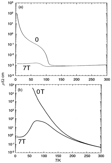 |
| | Fig. 8 T dependence
of the resistivity registered under 0 and 7 T for (a) Sm0.85Ca0.15MnO3
and (b) Pr0.7Ca0.3MnO3. | |
Phase separation: coexistence of ferromagnetism
and charge ordering
The appearance of ferromagnetism at low temperature in manganites is easily
explained by the DE model.6 However, this model
cannot explain the entire phase diagrams. More particularly, the role of charge
ordering in the magnetotransport properties is not taken into account in the
framework of double exchange. In the same way, magnetization and neutron diffraction
studies evidenced weak FM moments which could not be explained by DE alone.
In order to explain such features, several theoretical papers23–25
have proposed the existence of phase separation between hole undoped antiferromagnetic
regions and hole rich antiferromagnetic regions at low temperature. Arguments
for the coexistence of two phases, supporting the model of phase separation,
were also developed in several experimental works on manganites.26–29
The coexistence of the CO state with the FMM phase was shown, for instance,
by in situ observation on heating a Nd0.5Sr0.5MnO3
sample in an electron microscope.30 This was
interpreted as microscopic electronic phase separation. In a recent study
of manganites, Uhera and Cheong31 showed that
the coexistence of FM and CO can be dramatically influenced by cooling rate
and aging, and suggested that the origin of the phase separation is, in fact,
structural.These results demonstrate that the CO state plays a role in the transition
to the FMM state, and strongly suggest that the nature of the transition under
a magnetic field is percolative, so that ferromagnetic clusters within the
CO-AFM matrix are formed in a first step, the sample going from an AFMI
to a FMM behavior.
Mn-site doping: a chemical route to CMR
Bearing in mind the role of charge ordering in the magnetotransport properties
of the manganites, it should be possible to enhance the CMR properties of
these materials by weakening, or even by suppressing, the CO state using a
chemical route. The doping of Mn sites with various foreign cations is, in
this respect, a very efficient method, since it introduces disorder on the
Mn sites and is susceptible to breaking both orbital and charge ordering.The Mn-site doping of the charge ordered manganite Pr0.5Ca0.5MnO3
with various M cations (M = Mg2+, Fe3+,
Al3+, Ga3+, Ti4+, Sn4+)
leads to destruction of the charge ordering.32
For example, the signatures of the CO on both the ρ(T)
(Fig. 9) and χ′(T)
curves (Fig. 10) have disappeared
with only 3% dopant, and a weak ferromagnetic component is observed
at low temperature on the χ′(T) curves (Fig. 10). Consequently, CMR properties
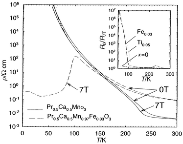
are induced by doping, as exemplified for Pr0.5Ca0.5Mn0.97Fe0.03O3
(Fig. 11). But the most spectacular effect
is obtained by doping the Mn sites with magnetic elements, such as Cr, Co,
Ni and Ru. In the series Pr0.5Ca0.5Mn1 − xMxO3
with M = Cr, Co, Ni, it is shown33–35
that a magnetic field is not required to induce insulator to metal transitions.
Clear I–M transitions are observed, in the absence of magnetic field
in the Cr doped material Pr0.5Ca0.5Mn1 − xCrxO3
for x values as low as 0.02 (Fig. 12).
Correlatively, the M(T) curves (Fig. 13)
show that the metallic state at low temperature is associated with ferromagnetism,
large magnetization values of 3 μB, close to
the theoretical magnetic moment, being reached. The disappearance of charge
ordering by chromium doping was clearly evidenced by the electron microscopy
study of Sm0.5Ca0.5Mn0.97Cr0.03O3.
As a consequence of the disappearance of CO, CMR behavior similar to that
of the hole doped manganites, without any CO, is restored. This is illustrated
in Fig. 14, where the ρ(T)
curves recorded at 0 and 7 T allow Pr0.5Ca0.5Mn0.97Cr0.03O3
to be compared with Pr0.7Ca0.2Sr0.1MnO3.
Similar results are obtained for cobalt and nickel doping, but chromium is
the most efficient cation to induce ferromagnetism.
 |
| | Fig. 9 ρ(T)
curves of Pr0.5Ca0.5MnO3
(pristine compound)
and of the corresponding doped manganites Pr0.5Ca0.5Mn0.97M0.03O3
(M = Mg2+, Al2+, Fe3+, Ti4+,
Sn4+). | |
 |
| | Fig. 10 Dependence of the
real part of the susceptibility (χ′) for Pr0.5Ca0.5MnO3
and 3% doped Pr0.5Ca0.5Mn0.97M0.03O3
samples (M = Mg2+, Fe3+,
Ti4+). | |
 |
| | Fig. 11 Dependence of the
resistivity (ρ) on T for Pr0.5Ca0.5MnO3
and Pr0.5Ca0.5Mn0.97Fe0.03O3
recorded at 0 and 7 T. Inset: dependence on T of the R0/R7T
ratios, demonstrating the CMR induced by doping with M = Fe
and Ti. | |
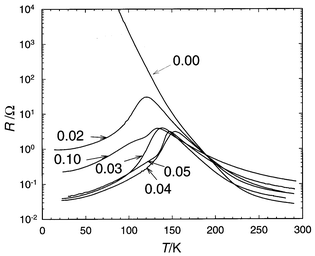 |
| | Fig. 12 ρ(T)
curves of the Pr0.5Ca0.5Mn1 − xCrxO3
samples; the solid line corresponds to x = 0. | |
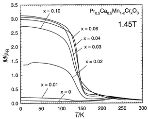 |
| | Fig. 13 Pr0.5Ca0.5Mn1 − xCrxO3: M(T) curves. | |
 |
| | Fig. 14 ρ(T)
recorded at 0 and 7 T for the Cr doped Pr0.5Ca0.5Mn0.97Cr0.03O3
manganite. The same curves for a classical charge delocalized Ln0.7A0.3MnO3
manganite are also given. | |
In fact, further studies of the Cr doped manganites36,37
clearly establish that the transformation of the CO state into the FM state
takes place by a phase separation mechanism. Coexistence of CO domains with
the ferromagnetic metallic phase is clearly evidenced by electron diffraction
at low temperature.37 This is illustrated
by the ED pattern and lattice image of the manganite Pr0.5Ca0.5Mn0.95Cr0.05MnO3
measured at 92 K (Fig. 15).
The [010] ED pattern (top Fig. 15)
shows that the superlattice reflections are indeed in an incommensurate position (q = 0.42),
whereas they were close to the commensurate positions (q ≈ 0.48)
in the undoped material. The lattice image (bottom Fig. 15)
shows that the order is partly destroyed, i.e. ordered and non-ordered
domains with variable sizes coexist throughout the crystal, the first corresponding
to CO regions and the second being attributed to ferromagnetic regions.
![[010] ED
pattern of Pr0.5Ca0.5Mn0.95Cr0.05MnO3
recorded at 92 K. Arrows indicate superlattice reflections.](/image/article/2001/JM/b003243n/b003243n-f15.gif) |
| | Fig. 15 [010] ED
pattern of Pr0.5Ca0.5Mn0.95Cr0.05MnO3
recorded at 92 K. Arrows indicate superlattice reflections. | |
These results show that magnetic ions, like chromium, not only destroy
charge ordering, but also participate in ferromagnetism. In the case of chromium,
the following scenario can be proposed:37
as Cr3+ replaces the isovalent Mn3+ cation
it goes with reversed spin, leading to a decrease of the magnetic moment (3.15 μB
observed instead of 3.45 μB without altering
the spin direction). Direct evidence of spin reversal was given by a
magnetic dichroism study on the same compound.38
The spin configuration before and after chromium doping can be schematized
as shown in Fig. 16. Without chromium (top Fig. 16) the antiferromagnetic ordering
is of the CE type below 170 K, with two FM zig-zag chains antiferromagnetically
coupled in the ac plane, such planes are stacked along b
with reversed spins. Thus, in the undoped CE-type phase, metallic conduction
along the FM zig-zag chains is inhibited by the strong repulsive Coulombic
interaction between the charge carriers and interchain AFM coupling. After
chromium doping (bottom Fig. 16),
the occupation of some Mn positions by Cr3+ with reversed
spins breaks the AFM coupling between the chains and forms local ferromagnetic
clusters (circled region at the bottom of Fig. 16).
Thus, for a very small doping level (x < 0.05),
the eg electron is itinerant within these clusters, but in the
regions outside the clusters, charge and AFM ordering are weakened but still
preserved. Thus, the insulating state breaks into majority CO domains, with
either spins ordered antiferromagnetically or fluctuating within them, and
minority ferromagnetic metallic domains. The size of the CO-AFM domains
decreases as x increases and then metallicity appears in a percolative
way.
 |
| | Fig. 16 Schematic spin configuration
of Pr0.5Ca0.5MnO3
(top) and Pr0.5Ca0.5Mn1 − xCrxO3
(bottom). The dashed zig-zag
lines are to illustrate interchain ferromagnetic coupling. The region enclosed
by the circle represents the ferromagnetic cluster formed by two Cr3+
cations. Mn3+ eg orbital ordering is also shown
as lobes. Cr substitution weakens orbital ordering, as shown in the lower
part of the figure. | |
The possibility of inducing an I–M transition in a CO manganite,
Nd0.5Ca0.5MnO3, by ruthenium doping was shown
for the first time by Rao et al.,39
the Curie temperature increasing with the ruthenium content. The doping of
the Mn(IV)-rich manganites Ln0.4Ca0.6MnO340 and CaMnO341
with ruthenium shows that the potential of this cation to induce metallicity
and ferromagnetism is still superior to Cr, Co and Ni. This is illustrated
by the ρ(T) and M(T)
curves (Fig. 17) of the Pr0.4Ca0.6Mn1 − xRuxO3 series. It can be seen that, starting
from an insulating phase (x = 0, upper inset
in Fig. 17), the resistivity is
lowered in a spectacular way, by several orders of magnitude on doping with
ruthenium, showing “double bump” curves (Fig. 17).
Correlatively, ferromagnetism is induced in a spectacular way, the magnetic
moment reaching a maximum value of 2.8 μB at
4 K for x = 0.06 (lower inset in Fig. 17). These results show that Ru weakens
charge ordering, but the disappearance of CO is not sufficient to explain
the appearance of ferromagnetism and metallicity at low temperature and also
the double bump phenomenon on the ρ(T) curves.
Again, they can be interpreted on the basis of the phase separation scenario.23–29 For
low doping levels, FM clusters are formed around the Ru cations within the
AFM insulating matrix, so that, for x = 0.02,
CO coexists with these FM clusters and the resistivity is not affected significantly.
For higher doping levels (x ≈ 0.04), metallic
FM regions coexist with insulating AFM regions. The first bump at high temperature
on the ρ(T) curve (Fig. 17)
corresponds to the I–M transition within the FM regions, whereas the
second bump at lower temperature characterizes the competitive contribution
of both regions, AFM insulating and FM metallic, to the conductivity. Finally,
for x = 0.10, the percolation of FM clusters and
their large domains can be explained by the ability of this element to exhibit
two high oxidation states, Ru(IV) and Ru(V).
The t2g3 configuration of Ru(V)
is similar to Mn(IV), whereas the t2g4
configuration of Ru(IV) is different from the t2g3eg1
configuration of Mn(III). Mn(III)
can interact with both Ru(V) and Ru(IV)
via
ferromagnetic superexchange interaction involving overlap of the partly filled
eg orbital of Mn(III) and the empty eg
orbitals of Ru(IV) and Ru(V). Thus,
its introduction on the Mn lattice not only tends to destroy the charge ordering,
but may contribute to the increased Mn3+ content according
to the equilibrium Mn4+ + Ru4+ ![[left over right harpoons]](https://www.rsc.org/images/entities/char_21cb.gif) Mn3+ + Ru5+. Consequently, FM clusters are generated not only by DE between
Mn species (Mn3+ + Mn4+ Mn4+ + Mn3+), but also by the FM superexchange interactions between Mn3+
and both Ru(IV) and Ru(V). Thus,
it is most probable that the FM clusters are formed around the Ru atoms, which
locally destroy CO and simultaneously favor DE.
Mn3+ + Ru5+. Consequently, FM clusters are generated not only by DE between
Mn species (Mn3+ + Mn4+ Mn4+ + Mn3+), but also by the FM superexchange interactions between Mn3+
and both Ru(IV) and Ru(V). Thus,
it is most probable that the FM clusters are formed around the Ru atoms, which
locally destroy CO and simultaneously favor DE.
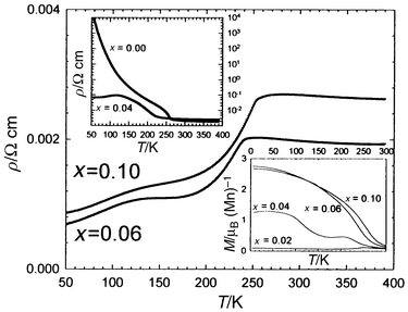 |
| | Fig. 17 ρ(T)
curves of Pr0.4Ca0.6Mn1 − xRuxO3.
Upper inset: x = 0 and x = 0.04 ρ(T)
curves. Lower inset: M(T) curves of Pr0.4Ca0.6Mn1 − xRuxO3. | |
Finally, it should be emphasized that the Ru doped manganites exhibit CMR
effects in spite of their metallic conductivity, as shown, for instance, for
Pr0.4Ca0.6Mn0.94Ru0.06O3
(Fig. 18a). More importantly, CMR is enhanced
in a spectacular way for lower doping levels, when smaller FM domains coexist
with AFM regions, as illustrated for Pr0.4Ca0.6Mn0.96Ru0.04O3
(Fig. 18b) which exhibits a resistance
ratio of 40 at 110 K under 7 T, whereas, under the same conditions,
the undoped phase is not magnetoresistive. Thus, this shows that the AFM regions
shrink under an external magnetic field, extending the FM clusters and eventually
leading to percolation.
 |
| | Fig. 18 ρ(T)
curves obtained upon cooling in 0 and 7 T (left y axis)
and ρ0(T)/ρ7T(T)
ratio (right y axis) for Pr0.4Ca0.6Mn1 − xRuxO3 with x = 0.06 (a) and x = 0.04 (b). | |
Concluding remarks
The few results presented in this study show the prime roles of charge
ordering and phase separation phenomena in the magnetotransport properties
of manganites, allowing us to explain and to discover a route to the generation
of new CMR properties. Many questions, however, still need to be answered
in order to understand the curious behavior of the manganites. The role of
orbital ordering and its interplay with charge and magnetic ordering is one
of the most important issues which has been the subject of only a few studies13,42-43 to date. Some results suggest,
for instance, that the incommensurate structure observed by electron microscopy
involves the presence of partial orbital disordering and complete charge ordering,
and that long range orbital ordering is never achieved so that charge order
drives the orbital order at the transition. Further systematic investigations
are necessary to understand all these phenomena.References
- E. O. Wollan and W. C. Koehler, Phys. Rev., 1955, 100, 545 CrossRef CAS.
- J. B. Goodenough, Phys.
Rev., 1955, 100, 564 CrossRef CAS.
- R. M. Kusters, J. Singleton, D. A. Keon, R. H. Greddy and N. Hayes, Physica
B, 1989, 155, 362 CrossRef CAS.
- A. Asamitsu, Y. Moritomo, Y. Tomioka and Y. Tokura, Nature, 1995, 373, 407 CrossRef CAS.
- A. Maignan, Ch. Simon, V. Caignaert and B. Raveau, Solid
State Commun., 1995, 96, 623 CrossRef CAS.
- C. Zener, Phys. Rev., 1951, 82, 403 CrossRef CAS.
- M. Uhera, S. Mori, C. H. Chen and S. W. Cheong, Nature, 1999, 399, 560 CrossRef CAS.
- S. Yunoki, J. Hu, A. Malvezzi, A. Moreo, N. Furukawa and E. Dagotto, Phys. Rev. Lett., 1998, 80, 845 CrossRef CAS.
- Y. Tomioka, A. Asamitsu, Y. Moritomo, H. Kuwahara and Y. Tokura, Phys.
Rev. Lett., 1995, 74, 5108 CrossRef.
- F. Damay, C. Martin, M. Hervieu, A. Maignan, B. Raveau, G. André and F. Bourée, J. Magn. Magn. Mater., 1998, 184, 71 CrossRef CAS.
- H. Kawano, R. Kajimoto, H. Yoshizawa, Y. Tomioka, H. Kuwahara and Y. Tokura, Phys.
Rev. Lett., 1997, 78, 4253 CrossRef CAS.
- P. M. Woodward, D.
E. Cox, T. Vogt, C. N. R. Rao and A. K. Cheetham, Chem.
Mater., 1999, 11, 3528 CrossRef CAS.
-
(a) C. H. Chen and S. W. Cheong, Phys. Rev. Lett., 1996, 76, 4042 CrossRef CAS;
(b) P. Radaelli, D. E. Cox, M. Marezio and S. W. Cheong, Phys. Rev. B, 1997, 55, 3015 CrossRef CAS.
- F. Damay, Z. Jirak, M. Hervieu, C. Martin, A. Maignan, B. Raveau, G. André and F. Bourée, J. Magn. Magn. Mater., 1998, 190, 221 CrossRef CAS.
-
(a) M. Hervieu, A. Barnabé, C. Martin, A. Maignan, F. Damay and B. Raveau, Eur.
Phys. J. B, 1999, 8, 31 CrossRef CAS;
(b) A. Barnabé, M. Hervieu, C. Martin, A. Maignan and B. Raveau, J. Mater. Chem., 1998, 8, 1405 RSC.
- Z. Jirak, S. Krupicka, Z. Simsa, M. Dlouha and S. Vratislav, J. Magn. Magn. Mater., 1985, 53, 153 CrossRef CAS.
- C. H. Chen, S. W. Cheong and H. Y. Hwang, J. Appl. Phys., 1997, 81, 4326 CrossRef CAS.
- N. Kumar and C. N. R. Rao, J. Solid State Chem., 1997, 129, 363 CrossRef CAS.
- A. Barnabé, M. Hervieu, C. Martin, A. Maignan and B. Raveau, J.
Appl. Phys., 1998, 84, 5506 CrossRef CAS.
- F. Damay, C. Martin, A. Maignan, M. Hervieu, B. Raveau, Z. Jirak, G. André and F. Bourée, Chem. Mater., 1999, 11, 536 CrossRef CAS.
- C. Martin, A. Maignan, M. Hervieu and B. Raveau, Phys.
Rev. B, 2000, 60, 12191 CrossRef CAS.
-
(a) C. Martin, A. Maignan, F. Damay, M. Hervieu and B. Raveau, J. Solid State Chem., 1997, 134, 198 CrossRef CAS;
(b) A. Maignan, C. Martin, F. Damay and B. Raveau, Chem. Mater., 1998, 10, 1974 CrossRef CAS;
(c) A. Maignan, C. Martin, F. Damay B. Raveau and J. Hejtmanek, Phys. Rev. B, 1998, 58, 2578 CrossRef CAS.
- S. Yunoki, J. Hu, A. Malvezzi, A. Moreo, N. Furukawa and E. Dagotto, Phys.
Rev. Lett., 1998, 80, 845 CrossRef CAS.
- E. Dagotto, S. Yunoki, A. Malvezzi, A. Moreo, J. Hu, S. Capponi, D. Poilblanc and F. Furukawa, Phys. Rev. B, 1998, 58, 6414 CrossRef CAS.
- S. Yunoki and A. Moreo, Phys. Rev. B, 1998, 58, 6403 CrossRef CAS.
- P. Schiffer, A. P. Ramirez, W. Bao and S.
W. Cheong, Phys. Rev. Lett., 1995, 75, 3336 CrossRef CAS.
- P.
G. Radaelli, D. E. Cox, M. Marezio, S. W. Cheong, P. Schiffer and A.
P. Ramirez, Phys. Rev. Lett., 1995, 75, 4488 CrossRef CAS.
- G. Allodi, R. De Renzi, G. Guidi, F. Licci and M. W. Piepper, Phys. Rev. B, 1997, 56, 6036 CrossRef CAS.
- G. Allodi, R. De Renzi, F. Licci and M.
W. Piepper, Phys. Rev. Lett., 1998, 81, 4736 CrossRef CAS.
- N. Fukumoto, S. Mori, N. Yamamoto, Y. Moritomo, T. Katsufuji, C. H. Chen and S. W. Cheong, Phys. Rev. B, 1999, 60, 12963 CrossRef CAS.
- M. Uhera and S. W. Cheong, Relaxation
Between Charge Order and Ferromagnetism in Manganites: Indication of Structural
Phase Separation, preprint. Search PubMed.
- F. Damay, C. Martin, A. Maignan and B. Raveau, J. Magn. Magn. Mater., 1998, 183, 143 CrossRef CAS.
- B. Raveau, A. Maignan and C. Martin, J. Solid State
Chem., 1997, 130, 162 CrossRef CAS.
- A. Maignan, F. Damay, C. Martin and B. Raveau, Mater.
Res. Bull., 1997, 32, 965 CrossRef CAS.
- A. Barnabé, A. Maignan, M. Hervieu, F. Damay, C. Martin and B. Raveau, Appl. Phys. Lett., 1997, 71, 3907 CrossRef CAS.
- Y. Moritomo, A. Machida, S. Mori, N. Yamamoto and A. Nakamura, Phys. Rev. B, 1999, 60, 9220 CrossRef CAS.
- R. Mahendiran, M. Hervieu, A. Maignan, C. Martin and B. Raveau, Solid
State Commun., 2000, 114, 429 CrossRef CAS.
-
(a) F. Studer, O. Toulemonde, J. B. Goedkoop, A. Barnabé and B. Raveau, Jpn. J. Appl. Phys., 1999, 38, 377 CrossRef CAS;
(b) O. Toulemonde, F. Studer, A. Barnabé, A. Maignan, C. Martin and B. Raveau, Eur.
Phys. J. B, 1998, 4, 159 CrossRef CAS.
- P. V. Vanitha, A. A. Rulraj, A. R. Raju and C. N. R. Rao, C. R. Acad.
Sci., 1999, 2, 595 Search PubMed.
- B. Raveau, A. Maignan, C. Martin, R. Mahendiran and M. Hervieu, J. Solid State Chem.,
in press. Search PubMed.
- B. Raveau, A. Maignan, C. Martin and M. Hervieu, Mater. Res. Bull., in
press. Search PubMed.
- S. Mori, T. Katsufuji, N. Yamamoto, C.
H. Chen and S. W. Cheong, Phys. Rev. B, 1999, 59, 13573 CrossRef CAS.
- M. Zimmermann, J. P. Hill, D. Gibbs, M. Blume, D. Casa, B. Keimer, Y. Murakami and Y. Tomika, Phys. Rev. Lett., 1999, 83, 4872 CrossRef CAS.
Footnote |
| † Basis of a presentation given at Materials Discussion No. 3,
26–29 September, 2000, University of Cambridge, UK. |
|
| This journal is © The Royal Society of Chemistry 2001 |
Click here to see how this site uses Cookies. View our privacy policy here.