DOI:
10.1039/B003198O
(Paper)
J. Mater. Chem., 2001,
11, 78-85
Crystal structure of the thallium strontium
cobaltite TlSr2CoO5 and its relationship to the electronic
properties†
Received
5th May 2000
, Accepted 26th June 2000
First published on 5th October 2000
Abstract
The complex cobaltite TlSr2CoO5 undergoes
a first-order metal–insulator phase transition at room temperature.
The structures of the high temperature (HT) and low temperature (LT)
phases have been refined on powder samples using electron diffraction, X-ray
diffraction and EXAFS. The HT-phase is isostructural with the so-called
1201-type cuprate. The unit cell is tetragonal (space group P4/mmm)
and cobalt occupies a highly elongated octahedron. At low temperature, a commensurate
modulation of the oxygen positions sets in such that two sites are available
for cobalt, in the ratio 1 to 2. The sizes and the distortions of these two
sites differ in such a way that a different electronic configuration of cobalt
is stabilized in each. This effect is described as a spin state disproportionation (SSD).
Long range ordering of these two spin states (SSO) is compared to
the charge ordering (CO) effect and SSO seems to play a role as
important for cobaltites(III) as CO does for nickelates or manganites.
1 Introduction
The thallium strontium cobaltite TlSr2CoO5 undergoes
a first-order metal–insulator transition near room temperature characterized
by an hysteresis loop and steep changes in the temperature dependences of
the magnetic susceptibility and of the electrical resistivity.1
The electrical resistivity, which is larger than 106 Ω cm
at 100 K, decreases as the temperature (T) increases,
reaching a value of 2 Ω cm at 270 K, and then rapidly
drops to 0.05 Ω cm near room temperature, becoming nearly
temperature independent. The Seebeck coefficient is positive at low temperature,
increases with T, exhibits a maximum of 200 µV K−1
at 150 K, then decreases and changes its sign at room temperature,
reaching a value of −15 µV K−1
at 310 K that very slightly and linearly decreases with temperature.
The molar magnetic susceptibility (χM = 8 × 10⁻³ mol−1 at 4 K) exhibits a peak at 150 K, attributed
to the onset of antiferromagnetic ordering, but does not vary much between
liquid helium and room temperature, where it sharply increases, almost doubling
its value. Above 300 K, χM rapidly decreases
following a Curie–Weiss law with a Curie constant of 1.7 emuCGS K mol−1
and a large positive Weiss constant of 200 K, denoting dominant very
strong ferromagnetic interactions that can be ascribed to a double exchange
mechanism. In conclusion, the low temperature (LT) phase is an antiferromagnetic
p-type insulator whereas the high temperature (HT) phase
is an n-type metal with dominant ferromagnetic interactions.
In a preliminary investigation the HT- and LT-phases were both described
as isostructural with the tetragonal form of the so-called 1201 member
of the well-known series of thallium strontium calcium cuprates.2 The tetragonal unit cell undergoes a significant
decrease in volume at the transition, the HT form being denser than the LT
form.
Extended X-ray absorption fine structure (EXAFS) studies
reveal a much wider dispersion of the Co–O distances at low temperature
than at high temperature. Electron diffraction (ED) patterns recorded
below ca. 250 K clearly show weak spots indicating a modulation
of the structure. Both series of results are reported below.
Since the difference between the structures of the HT- and LT-phases appears
minimal, there is no hope of growing single crystals in the very near future
and amounts of the compound large enough to allow neutron diffraction experiments
to be performed are not yet available, high resolution XRD data were recorded
using synchrotron radiation in order to carry out a refinement of the structure
by the Rietveld method on the basis of the unit cell and space group deduced
from the ED results.
The purpose of this paper is to account for the whole set of results and
to discuss the relationship between the structural and physical properties.
2 Experimental
Sample preparation and chemical analysis have been described previously.2 Starting materials were Tl2O3,
SrO and Sr2Co2O5 in the ratio 1∶2∶1.
The homogenized mixture was heated in a sealed gold tube at 900![[thin space (1/6-em)]](https://www.rsc.org/images/entities/char_2009.gif) °C
for 3 h. Such conditions are not far from those used for preparing
thallium cuprates. Generally, loss of thallium is observed, requiring a determination
of the composition and of the oxidation state of cobalt. The Tl, Sr and Co
contents were determined at the Service Central d'Analyses du CNRS.3 Two successive iodometric titrations were used for
the determination of the oxidation states of Tl and Co.2
Writing the general formula of the material as:
°C
for 3 h. Such conditions are not far from those used for preparing
thallium cuprates. Generally, loss of thallium is observed, requiring a determination
of the composition and of the oxidation state of cobalt. The Tl, Sr and Co
contents were determined at the Service Central d'Analyses du CNRS.3 Two successive iodometric titrations were used for
the determination of the oxidation states of Tl and Co.2
Writing the general formula of the material as:| | 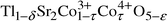 |
(1)
|
the most probable
values of δ, τ and ε for the investigated
sample are 0.07, 0.05 and 0.07, respectively.
A TEM study was carried out with a Jeol 2000 FX microscope equipped with
a double tilt sample holder. The temperature of the sample was controllable
between 100–350 K.
High resolution diffraction (HRD) data were collected at LURE (Laboratoire
pour l'Utilisation du Rayonnement Electromagnétique in Orsay)
on the DCI storage ring at the beam line DW22.4
Absorption spectra for the EXAFS study were recorded at 10, 100, 250 and
330 K between 7650 and 8750 eV with a step of 0.3 eV
and a counting time of 2 s.
3 Results
3.1 The high temperature tetragonal t-phase
At room temperature, the product contains two phases, but above ca.
310 K, only a single phase remains in the XRD patterns. It is isostructural
with the tetragonal form of the analogous cuprate5
(space
group: P4/mmm). For the purposes of comparison
with the LT-phase, selected ED patterns recorded at 350 K are given
in Fig. 1. These were obtained by tilting
around the c* axis, which can be easily identified,
and indexed with a tetragonal primitive cell. No additional reflections were
observed and the measured cell parameters are close to the expected values (a = 0.375, c = 0.877 nm).2 Reflection conditions agree with the tetragonal P4/mmm
space group. A typical high resolution image shows the absence of any extended
defects (Fig. 2).
 |
| | Fig. 1
ED patterns of a crystal
of the HT tetragonal form of TlSr2CoO5 recorded at 350 K.
| |
![High resolution image
of the HT tetragonal form of TlSr2CoO5 along the [01̄0]
zone axis, showing the absence of extended defects.](/image/article/2001/JM/b003198o/b003198o-f2.gif) |
| | Fig. 2
High resolution image
of the HT tetragonal form of TlSr2CoO5 along the [0![[1 with combining macron]](https://www.rsc.org/images/entities/char_0031_0304.gif) 0]
zone axis, showing the absence of extended defects. 0]
zone axis, showing the absence of extended defects.
| |
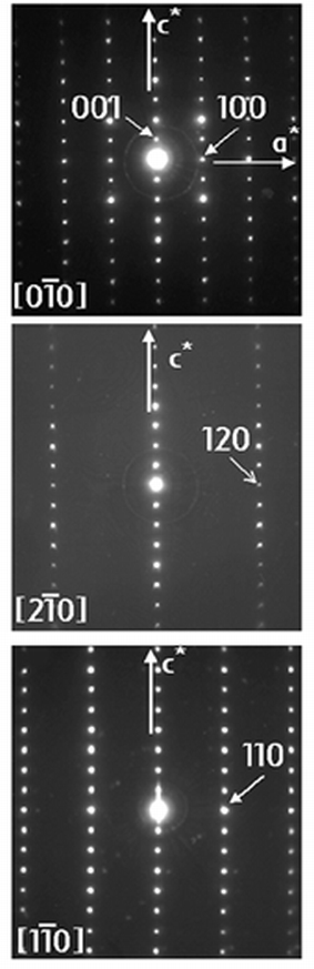
As both the HT- and LT-phases coexist at room temperature, XRD data
were collected at 373 K on a Siemens diffractometer using a copper
anticathode and equipped with a platinum heating sample holder, for 2θ
varying from 15 to 99° in steps of 0.015°. Structural parameters were
refined using the Rietveld method and the Fullprof program.6
Difficulties arose from the complex upward-bending shape of the background
at small diffraction angles (2θ < 40°)
and from the presence of the strong 200 peak of platinum at 46.5°, which
was introduced as a second phase; the background was modeled by linear interpolation
between 25 given points. Experimental and calculated diffractograms are given
in Fig. 3 and atomic positions are reported
in Table 1. The fractional occupancy
of the thallium site was also refined and the Tl deficiency determined (Table 1) was consistent with the results
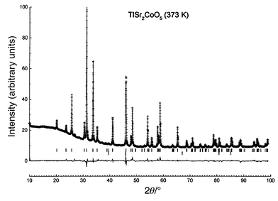
of chemical analysis. Relevant interatomic distances are given in Table 2, a drawing of the structure is presented
in Fig. 4 and the coordination environment
of the Co ions is shown in Fig. 5. Table 2 and Fig. 5
highlight the fact that the oxygen octahedron surrounding the Co atoms is
highly elongated. A similar distortion has been reported for Pb0.63Cu0.37Sr2CoO5.7 This elongation should be correlated to very short
apical Tl–O bond lengths, which is a general feature of thallium–oxygen
bonding. Such short Tl–O distances have previously been reported for
thallium cuprates8 and ferrites.9,10
It should also be noted that Tl atoms lie on an inversion centre (1a
site), unlike in cuprates where they are slightly shifted within the ab
plane from this ideal position.
 |
| | Fig. 3
Measured (discrete
points) and calculated (solid line) XRD intensities and their
differences for TlSr2CoO5 at 373 K. The strong
peak at 46.5° is the 200 peak of the platinum sample holder.
| |
 |
| | Fig. 4
Structure of the high
temperature form of TlSr2CoO5.
| |
 |
| | Fig. 5
Environment of the
cobalt atoms in the high temperature form of TlSr2CoO5.
| |
Table 1
Atomic positions in the high temperature
form of TlSr2CoO5 and refinement parametersa
| Atom |
Site multiplicity Wyckoff letter |
x
|
y
|
z
|
Fractional occupancy |
|
Cell parameters/nm: a = 0.37571(1); c = 0.87920(2).
Space group: P4/mmm. Isotropic overall temperature factor/Å2: B = 0.15.
Profile parameters: U = 0.072(3); V = −0.076(3); W = 0.035(1); η(pseudo-Voight) = 0.764(7).
Conventional Rietveld R-factors (%): Rp = 13.3; Rwp = 9.5; χ2 = 14; RBragg = 8.1; Rf = 8.8.
|
| Tl |
1a |
0 |
0 |
0 |
0.93(5) |
| Sr |
2h |
0.5 |
0.5 |
0.2903(3) |
1 |
| Co |
1b |
0 |
0 |
0.5 |
1 |
| O1 |
2g |
0 |
0 |
0.232(3) |
1 |
| O2 |
1c |
0.5 |
0.5 |
0 |
1 |
| O3 |
2e |
0 |
0.5 |
0.5 |
1 |
Table 2
Main interatomic distances in the high temperature
form of TlSr2CoO5
| Tl–O1 |
0.2045(8)
(×2) |
| Tl–O2 |
0.2651(1)
(×4) |
| |
|
| Co–O1 |
0.2346(8)
(×2) |
| Co–O3 |
0.1875(1)
(×4) |
| |
|
| Co–Sr |
0.3230(1)
(×8) |
| |
|
| Sr–O1 |
0.2705(2)
(×4) |
| Sr–O2 |
0.2550(1)
(×1) |
| Sr–O3 |
0.2634(1)
(×4) |
3.2 The low temperature orthorhombic o-phase
3.2.1 Electron diffraction.
ED patterns were recorded
at 100 K and are reported in Fig. 6
for two zone axes. Patterns A to C can be compared with the corresponding
ones in Fig. 1. All the patterns have
the following main features: (i) intense spots corresponding to
a tetragonal lattice similar to that used for describing the HT-phase
and (ii) weaker additional spots of variable intensities which cannot
be indexed using the space group P4/mmm. However, they
are always commensurate with the basic tetragonal network and are located
in such a way that d120 and d110 are
tripled (patterns B, C and D). Comparing the patterns of various
crystals, changing the beam section and shifting the samples reveals that
the crystals are actually twinned, the average size of microdomains being
smaller than 0.5 µm. The twins correspond to a rotation of π/2 radians
around the c axis, which is not surprising as the sublattice is tetragonal.
It was not possible to directly observe a crystal with a zone axis parallel
to ct
(the index t refers to the tetragonal
sublattice), but the whole reciprocal lattice can be built from the patterns
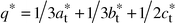
obtained with other orientations. The (at*,
bt*) plane deduced in this way is shown in Fig. 7.
All the diffraction patterns can be indexed assuming that two perpendicular
basic reciprocal lattices are superposed, as shown in Fig. 7.
 |
| | Fig. 6
ED patterns of the
LT-phase of TlSr2CoO5 recorded at 100 K.
| |
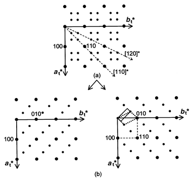 |
| | Fig. 7
(at*,
bt*) plane deduced from various experimental
patterns (a) and its decomposition into two orthogonal reciprocal
planes (b).
| |
The whole set of patterns can be interpreted using a modulation vector:
| |  |
(2)
|
In
other words, each intense spot of the tetragonal sublattice is accompanied,
in the direction of the
q* vector, by three spots of
decreasing intensities, the third having a vanishing intensity. This
q*
vector is drawn in the pattern of
Fig. 8.
Using
q* makes it possible to index all the spots with
four indices,
h,
k,
l and
m, where
m
stands for the satellite order. For instance, some spots in
Fig. 8
are indexed in this way.
![Drawing of an ED pattern
along the [11̄0] zone axis where open circles represent
spots of weaker intensity and showing the q* modulation
vector. Spot indexing refers to the tetragonal subcell. The 4th index is the
satellite order.](/image/article/2001/JM/b003198o/b003198o-f8.gif) |
| | Fig. 8
Drawing of an ED pattern
along the [10] zone axis where open circles represent
spots of weaker intensity and showing the q* modulation
vector. Spot indexing refers to the tetragonal subcell. The 4th index is the
satellite order.
| |
3.2.2 XRD: structure refinement.
As the modulation
is commensurate, refinement of the structure can be approximated using a superstructure
and a 3D space group. Two possible supercells are drawn in Fig. 7.
The larger one (the smaller in real space) is monoclinic (dotted
line in Fig. 7). Diffraction conditions
for 0k0 are k = 2n, leading
to two possible space groups: P21 and P21/m.
However, refinements carried out using these models were not satisfactory:
for instance, the RBragg factor always remained larger
than 12%.
To overcome this difficulty we chose a larger (in real space),
but more symmetric supercell, also shown in Fig. 7
(solid
line). This cell is orthorhombic and related to the tetragonal subcell
by:
| |  |
(3)
|
Reflection conditions for
hkl are
h +
k = 2
n,
denoting a base-centered Bravais lattice of C type, and for
h0
l,
l = 2
n.
Two space groups are possible:
Cmcm and
Cmc2
1.
As usual, we chose the more symmetric of the two,
i.e.Cmcm.
The starting atomic coordinates were calculated from those found for the HT-phase
using the relationship:
| |  |
(4)
|
For the refinement, we assumed the same thermal
factors for atoms of the same nature. The
synchrotron radiation wavelength
was equal to 0.106942 nm. The data were recorded for 5 ≤ 2
θ ≤ 75°,
with a step size of 0.02°. The results of the refinement are given in
Table 3 and selected interatomic distances
in
Table 4.
Table 3
Atomic positions in the low temperature form
of TlSr2CoO5, profile parameters and reliability factorsa
| Atom |
Site multiplicity Wyckoff letter |
x
|
y
|
z
|
B/Å2 |
Fractional occupancy |
|
Cell parameters/nm: a = 0.53311(2); b = 1.59697(4); c = 1.75422(4).
Space group: Cmcm. Profile parameters: U = 0.065(5); V = −0.021(3); W = 0.0107(4); η(pseudo-Voight) = 0.108(7).
Conventional Rietveld R-factors (%): Rp = 14.7; Rwp = 18.1; χ2 = 8.3; RBragg = 8.4; Rf = 11.2.
|
| Tl1 |
4c |
0 |
0.0183(3) |
0.25 |
0.86(4) |
0.973(4) |
| Tl2 |
4c |
0 |
0.3154(3) |
0.25 |
0.86(4) |
0.973(4) |
| Tl3 |
4c |
0 |
0.6660(3) |
0.25 |
0.86(4) |
0.973(4) |
| Co1 |
4a |
0 |
0 |
0 |
0.189(4) |
1 |
| Co2 |
8f |
0 |
0.3343(6) |
−0.0065(4) |
0.189(4) |
1 |
| Sr1 |
8f |
0 |
0.5013(6) |
0.3949(4) |
0.14(5) |
1 |
| Sr2 |
8f |
0 |
0.1684(6) |
0.3980(3) |
0.14(5) |
1 |
| Sr3 |
8f |
0 |
−0.1662(6) |
0.3938(3) |
0.14(5) |
1 |
| O1 |
8f |
0 |
0.0052(26) |
0.3749(23) |
0.46(23) |
1 |
| O2 |
8f |
0 |
0.3461(26) |
0.3667(18) |
0.46(23) |
1 |
| O3 |
8f |
0 |
−0.3224(29) |
0.3796(19) |
0.46(23) |
1 |
| O4 |
4c |
0 |
0.5307(30) |
0.25 |
0.46(23) |
1 |
| O5 |
4c |
0 |
0.1638(35) |
0.25 |
0.46(23) |
1 |
| O6 |
4c |
0 |
−0.1868(29) |
0.25 |
0.46(23) |
1 |
| O7 |
8d |
0.25 |
0.25 |
0 |
0.46(23) |
1 |
| O8 |
16h |
0.2231(60) |
0.0840(15) |
−0.0051(12) |
0.46(23) |
1 |
Table 4
Selected interatomic distances in the low
temperature form of TlSr2CoO5
| Bond |
Distance/nm |
| Tl1–O1 |
0.2201(40)
(×2) |
| Tl1–O4 |
0.2673(4)
(×2) |
| Tl1–O5 |
0.2324(55)
(×1) |
| Tl1–O6 |
0.3277(47)
(×1) |
| |
|
| Tl2–O2 |
0.2105(32)
(×2) |
| Tl2–O4 |
0.3438(50)
(×1) |
| Tl2–O5 |
0.2422(55)
(×1) |
| Tl2–O6 |
0.2660(1)
(×2) |
| |
|
| Tl3–O3 |
0.2280(33)
(×2) |
| Tl3–O4 |
0.2160(48)
(×1) |
| Tl3–O5 |
0.2666(1)
(×2) |
| Tl3–O6 |
0.2350(47)
(×1) |
| |
|
| Co1–O1 |
0.2196(41)
(×2) |
| Co1–O8 |
0.1795(28)
(×4) |
| |
|
| Co2–O2 |
0.2470(32)
(×1) |
| Co2–O3 |
0.2006(34)
(×1) |
| Co2–O7 |
0.1898(7)
(×2) |
| Co2–O8 |
0.1981(30)
(×2) |
| |
|
| Sr1–O1 |
0.2689(5)
(×2) |
| Sr1–O2 |
0.2528(42)
(×1) |
| Sr1–O3 |
0.2827(47)
(×1) |
| Sr1–O4 |
0.2585(12)
(×1) |
| Sr1–O8 |
0.2668(26)
(×2) |
| Sr1–O8 |
0.2766(26)
(×2) |
| |
|
| Sr2–O1 |
0.2637(43)
(×1) |
| Sr2–O2 |
0.2891(42)
(×1) |
| Sr2–O3 |
0.2689(5)
(×2) |
| Sr2–O5 |
0.2597(6)
(×1) |
| Sr2–O7 |
0.2584(7)
(×2) |
| Sr2–O8 |
0.2601(25)
(×2) |
| |
|
| Sr3–O1 |
0.2757(43)
(×1) |
| Sr3–O2 |
0.2715(6)
(×2) |
| Sr3–O3 |
0.2509(47)
(×1) |
| Sr3–O6 |
0.2545(9)
(×1) |
| Sr3–O7 |
0.2653(6)
(×2) |
| Sr3–O8 |
0.2507(25)
(×2) |
Measured and calculated XRD patterns are displayed in Fig. 9.
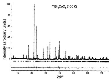 |
| | Fig. 9
Measured (discrete
points) and calculated (solid line) XRD intensities for TlSr2CoO5
at 100 K. Differences between measured and calculated values are also
displayed.
| |
3.2.3 Description of the LT-phase structure.
A
perspective view of the LT-phase structure is reproduced in Fig. 10.
If only Tl–O distances shorter than 0.27 nm are taken into account,
the Tl1 and Tl2 thallium atoms are located in a distorted pyramid. The third
Tl atom, Tl3, occupies a very distorted octahedral site with two short apical
Tl–O distances. The Tl–O distances are in agreement with those
reported earlier for thallium cuprates8 and
reflect the ability of thallium to accommodate various more or less distorted
sites, as, for instance, in Ba2Tl2O5
(distorted
tetrahedron),11 Sr4Tl2O7
(square),
Ca2Tl2O512
and Sr2Tl2O513
(distorted
octahedron). It should be pointed out that two apical Tl–O distances
are very short, allowing a significant elongation of the CoO6 octahedra
along the c axis. Refining the fractional site occupancy for Tl provides
a value smaller than unity (0.97), in agreement with the chemical
analysis discussed above, but larger than the value found for the tetragonal
HT-phase (0.93). We will assume a final value of 0.95 ± 0.02.
Further investigation will be required in order to gain better control of
the Tl stoichiometry and sample homogeneity, but it appears difficult to avoid
Tl loss during synthesis.
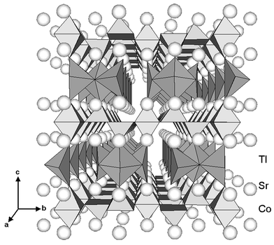 |
| | Fig. 10
Perspective drawing
of the LT-phase structure. Differences compared to the HT-phase are
stressed by taking into account Co–O distances shorter than 0.24 nm
and Tl–O distances shorter than 0.3 nm for the determination
of coordination polyhedra around Co and Tl, respectively.
| |
Two sites, labeled I and II, were found for the cobalt atoms. Site I is
a highly elongated octahedron with four very short Co–O distances of
0.179 nm in the (ao, bo)
plane. Site II is larger and more distorted with one long Co–O distance
of 0.247 nm, giving rise to a coordination of 5 + 1 (Fig. 11).
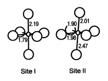 |
| | Fig. 11
Environment of the
cobalt atoms in the two Co sites of the low temperature form of TlSr2CoO5.
| |
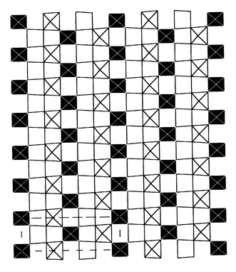
Fig. 12 shows the perovskite-type
CoO3 layers at z = 0 where polyhedra
corresponding to site I and II are distinguished. This drawing shows the way
in which the two kinds of cobalt atoms are ordered within the layers. The
larger II sites form zigzag chains along the ao
direction separated by the smaller I sites.
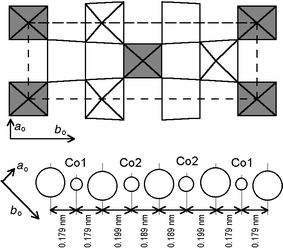 |
| | Fig. 12
CoO2 layer
at z = 0 showing the ordering of site I (darker)
and site II and the modulation of the Co–O distances along the at
direction.
| |
Fig. 12 also displays the succession
of cobalt and oxygen atoms along the at = (1/2)ao + (1/6)bo direction. It will be noted that the Co atoms
remain regularly spaced as in the HT tetragonal form, whereas the oxygen atoms
are shifted from the central position with a periodicity commensurate with
the cobalt distribution, but three times smaller.
3.2.4 EXAFS study.
The EXAFS study has been carried
out at the cobalt K-edge (EK = 7710 eV).
For Fourier analysis the photoelectron wave vector k-window
spanned from 60 to 135 nm−1 and the real R-space
window from 0.15 to 0.45 nm.
Fourier transforms (FT) show four peaks, with a shoulder on one
of them, which can be directly ascribed to the first five coordination shells
of cobalt atoms associated with Co–Oxy
(the
subscript xy refers to equatorial oxygen atoms), Co–Oz
(the
subscript z refers to apical oxygen atoms), Co–Sr, Co–Co
and Co–Tl distances, respectively.
3.2.4.1 EXAFS study at 330 K.
Using the lattice
parameters of the tetragonal unit cell of the HT-phase, the EXAFS spectra
were first refined assuming a single scattering process. Eleven parameters
have been refined (five radial distances, their respective Debye–Waller
factors and the edge energy). Final values are given in Table 5
and EXAFS oscillations with corresponding FT are displayed in Fig. 13a.
The calculated peak corresponding to the third coordination shell associated
with the Co–Co distances is much smaller than the experimental one.
This discrepancy should be related with the result of the refinement leading
to a value of the Co–Co distance that is not twice the Co–O one (Table 6) as one might have expected from
the above structural model and with a vanishing value of the Debye–Waller
factor. In order to improve the fitting we have taken into account second-
and third-order multiple scattering: the existence of linear –Co–O–Co–O–
chains within the CoO2 layers could favor such effects. For that
purpose we have considered the atomic environment of cobalt given in Table 6 where the parameters a, c
and z are to be refined. Origin shift and the ten coordination shells
have been refined in a first step then, in a second run, their associated
Debye–Waller factors. Results are given in Table 7
and EXAFS oscillations with corresponding FT are displayed in Fig. 13b.
Second- and third-order scattering are mainly significant for the Co–Co
coordination shell.14
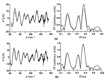 |
| | Fig. 13
Experimental (solid
line) and calculated (dotted line) EXAFS spectra and their
respective Fourier transforms for TlSr2CoO5, assuming
single (a) or multiple diffusion (b).
| |
Table 5
Results of the EXAFS data analysis at 330 K
assuming single scattering
| Distances/nm |
2σ2/10−2 nm2 |
| Co–Oxy |
0.184 ± 0.001 |
0.004 |
| Co–Oz |
0.224 ± 0.001 |
0.008 |
| Co–Sr |
0.316 ± 0.002 |
0.020 |
| Co–Co1 |
0.378 ± 0.002 |
0.000 |
| Co–Tl |
0.438 ± 0.002 |
0.013 |
Table 6
Cartesian coordinates of atoms surrounding
the central cobalt atom used for multiple scattering calculations
| |
x
|
y
|
z
|
d
|
| Co |
0 |
0 |
0 |
|
| Oxy1 |
a/2 |
0 |
0 |
a/2 |
| Oxy2 |
0 |
a/2 |
0 |
a/2 |
| Oz |
0 |
0 |
z
|
z
|
| Sr1 |
a/2 |
a/2 |
a/2 |
√3a/2 |
| Sr2 |
a/2 |
a/2 |
−a/2 |
√3a/2 |
| Sr3 |
a/2 |
−a/2 |
a/2 |
√3a/2 |
| Sr4 |
−a/2 |
a/2 |
a/2 |
√3a/2 |
| Co1 |
a
|
0 |
0 |
a
|
| Co2 |
0 |
−a |
0 |
a
|
| Tl |
0 |
0 |
c/2 |
c/2 |
Table 7
Results of the EXAFS data analysis at 330 K
for TlSr2CoO5, assuming multiple scattering
| Distances/nm |
2σ2/10−2 nm2 |
| Co–Oz |
0.228 ± 0.001 |
0.013 |
| Co–Oxy1 |
0.187 ± 0.001 |
0.004 |
| Co–Oxy2 |
0.186 ± 0.001 |
0.004 |
| Co–Sr1 |
0.321 ± 0.002 |
0.015 |
| Co–Sr2 |
0.319 ± 0.002 |
0.018 |
| Co–Sr3 |
0.319 ± 0.002 |
0.020 |
| Co–Sr4 |
0.320 ± 0.002 |
0.019 |
| Co–Co1 |
0.374 ± 0.002 |
0.007 |
| Co–Co2 |
0.374 ± 0.002 |
0.009 |
| Co–Tl |
0.438 ± 0.002 |
0.024 |
3.2.4.2 Temperature dependence of EXAFS.
Fig. 14
shows the FT of EXAFS spectra recorded at 10, 100, 250 and 330 K. The
behavior of the peaks related to the Co–Co, Co–Sr and Co–Tl
coordination shells seems normal, since the Debye–Waller factor decreases
with decreasing temperature, which leads to the increase of the peak intensity
that can be seen in Fig. 14. Conversely,
the intensity of the Co–Oxy peak drops significantly
as the temperature is reduced from 330 to 250 K, although there is
little additional change upon further cooling. Obviously, such behavior reflects
the sharp first-order phase transition occurring at room temperature and is
in excellent agreement with the XRD results. This confirms that the structural
change is mainly due to a modulation of the Co–O distances, as only
the corresponding peaks do not follow the anticipated simple thermal effect.
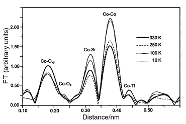 |
| | Fig. 14
Fourier transforms
of EXAFS oscillations of TlSr2CoO5 at 10, 100, 250 and
330 K.
| |
4 Discussion
As already mentioned in the introduction, the difference between the XRD
pattern of the HT tetragonal phase and that of the LT orthorhombic phase is
very small. The determination of the structures as well as the EXAFS study
show that it mainly results from the change in the oxygen atom positions.
We have found two sites for the Co atoms markedly differing in symmetry, distortion
and even the average Co–O distances (or the coordination number).
The average Co–O bond length is 0.193 nm for site I and 0.204 nm
for site II, if we assume sixfold coordination (0.195 nm for fivefold
coordination of site II). This large difference in the Co surroundings
must give rise to different electronic configurations. Obviously, disproportionation
of Co3+ into Co2+ and Co4+
would give an equal amount of sites I and II against an actual ratio of 1∶2.
Therefore, such a charge disproportionation does not take place and, on the
basis of ideas already proposed by Goodenough,15e.g.
for LaCoO3,16 we use the concept
of spin state disproportionation
(SSD) to account for the
splitting of a single average spin state at high temperature into two different
spin states at low temperature. Nevertheless, for LaCoO3, the MIT
is not sharp and smoothly spreads over a large temperature range of several
hundreds of degrees. To our knowledge, no long range ordering has been found
at low temperature. From a structural point of view, it should be emphasized
that TlSr2CoO5 differs greatly from LaCoO3
in the large elongation of the CoO6 octahedra. This elongation
can be associated with the layer-type structure of TlSr2CoO5,
which contrasts with the more isotropic perovskite-type structure of LaCoO3.
Fig. 15 shows the possible electronic
configurations of Co3+. The low spin (LS) state
is generally stabilized in octahedral sites where the six Co–O distances
are short and equal, as in LiCoO2 or CuCoO2. Clearly,
the huge elongation of site I should favor a strong drop in the energy of
the dz2 level and a shrinking of the equatorial
Co–O distances should raise the dx2 − y2
orbitals to a much higher energy. This prediction has been confirmed by tight
binding extended Hückel calculations17
(Fig. 16) which lead to the conclusion
that, in site I, Co3+ ions exhibit an intermediate spin (IS)
configuration (S = 1). For site II,
the variation in the Co–O distances is much smaller than for site I
and the splitting of eg orbitals due to octahedral distortion is
also much smaller, as seen in Fig. 16.
Hence a HS state is expected. The spin state of Co3+ in the
HT-phase is more complex, especially since it must account for the metallic
character, and has been discussed elsewhere on the basis of physical properties,
including a Mössbauer investigation of a 57Fe-doped sample.18 The spin state can be described as a fluctuating
mixture of IS and HS configurations. This mixed configuration disproportionates
at the transition into localized IS and HS configurations. The corresponding
I and II sites are well ordered thanks to the commensurate modulation of the
oxygen positions in the o-phase. Drawing the (ao, bo)
plane at the z = 0 level for several cells allows
the zigzag chains of II sites extending along the ao
direction separated by isolated I sites to be seen (Fig. 17).
This picture resembles the stripes resulting from charge ordering (CO)
in recently investigated mixed valence systems.19
For this reason, we introduce here the concept of spin state ordering
(SSO).
In a similar way to charge disproportionation and CO effects, SSD and SSO
account well for the correlation between the metal–insulator transition
and the structural change.
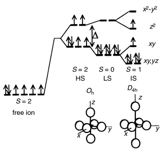 |
| | Fig. 15
Electronic configurations
of Co3+ ions with respect to site symmetry.
| |
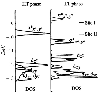 |
| | Fig. 16
d-orbital shift
and splitting for cobalt in site I and site II of the LT-phase with respect
to the HT-phase.
| |
 |
| | Fig. 17
Drawing of the z = 0
CoO2 layer over several unit cells showing the long range ordering
of Co atoms.
| |
5 Conclusions
Although a first-order phase transition has been found for TlSr2CoO5
at room temperature, only a sharp shrinking of the unit cell upon heating
was found in a preliminary investigation. The present work shows that a change
of symmetry actually occurs at the transition. The main effect is the occurrence
of a commensurate modulation of the position of the oxygen atoms which, in
turn, leads to the formation of two sites for Co3+ ions at
low temperature (against a single one at high temperature) strongly
differing in the distribution of Co–O distances. The features of the
structure modulation will be more accurately determined using neutron diffraction
in a forthcoming study. This segregation of Co atoms does not correspond to
a charge disproportionation, but to a spin state disproportionation. This
structural change is clearly correlated with the change in electronic properties,
explaining why the metallic character of the HT-phase is not present in
the low temperature phase. In order to describe the situation in the LT-phase,
the concept of spin state ordering (SSO) has been introduced and
compared with charge ordering and the formation of stripes, discovered a few
years ago in copper, nickel and manganese complex oxides.
References
- M. Coutanceau, J. P. Doumerc, J. C. Grenier, M. Pouchard and D. Sedmidubsky, Solid State Commun., 1995, 96, 56.
- M. Coutanceau, J. P. Doumerc, J. C. Grenier, P. Maestro, M. Pouchard and T. Seguelong, C. R. Acad. Sci. (Paris), 1995, 320, 675 Search PubMed.
- Service Central d'Analyses, CNRS, BP 22, F-69390 Vernaison,
France..
-
http://www.lure.u-psud.fr/Experiences/PE_DCI_ENG.HTM
.
- A. K. Ganguli and M. A. Subramanian, J. Solid State Chem., 1991, 93, 250 CAS.
-
J. Rodriguez-Carvajal, FullProf Program, ILL, Grenoble, 1995. .
- J. S. Kim, J. S. Swinnea and H. Steinfink, J.
Less-Common Met., 1989, 156, 347 Search PubMed.
-
M. Hervieu, C. Michel and B. Raveau, in Thallium-Based High-Temperature
Superconductors, ed. A. M. Herman and J.
V. Yakhmi, Marcel Dekker Inc., New York, 1993, p. 41. Search PubMed.
- R. Beyers, S. S. P. Parkin, V. Y. Lee, A.
I. Nazzal, R. Savoy, G. Gorman, T. C. Huang and S. La Placa, Appl. Phys. Lett., 1988, 53, 432 CrossRef CAS.
- T. Seguelong, P. Maestro, J. C. Grenier, L. Fournès and M. Pouchard, Physica B, 1995, 215, 427 CrossRef CAS.
- R. V. von Schenck and H. Müller-Buschbaum, Z. Anorg. Allg. Chem., 1974, 403, 197 CrossRef.
- R. V. von Schenck and H. Müller-Buschbaum, Z. Anorg. Allg. Chem., 1973, 396, 111.
- M. Coutanceau, J.-P. Doumerc, M. Chambon and J.-C. Grenier, C. R. Acad. Sci. (Paris), 1995, 320, 531 Search PubMed.
-
M. Coutanceau, Thesis, Bordeaux
I University, 1996, No. 1631..
- J. B. Goodenough, J. Phys. Chem. Solids, 1958, 6, 287 CrossRef CAS.
- M. A. Señaris-Rodríguez and J. B. Goodenough, J. Solid
State Chem., 1995, 116, 224 CrossRef CAS.
- J.-P. Doumerc, J.-C. Grenier, P. Hagenmuller, M. Pouchard and A. Villesuzanne, J.
Solid State Chem., 1999, 147, 211 CrossRef CAS.
- J.-P. Doumerc, M. Coutanceau, L. Fournès, J.-C. Grenier, M. Pouchard and A. Wattiaux, C. R. Acad. Sci. (Paris), 2000, 2, 637 Search PubMed.
- J. M. Tranquada, B. Sternlieb, J. D. Axe, Y. Nakamura and S. Uchida, Nature, 1995, 375, 561 CrossRef.
Footnote |
| † Basis of
a presentation given at Materials Discussion No. 3, 26–29 September,
2000, University of Cambridge, UK. |
|
| This journal is © The Royal Society of Chemistry 2001 |
Click here to see how this site uses Cookies. View our privacy policy here.