Characterization of switched direct current gas sampling glow discharge ionization source for the time-of-flight mass spectrometer
John P. Guzowski Jr. and Gary M. Hieftje*
Indiana University, Department of Chemistry, Bloomington, IN 47405, USA
First published on UnassignedUnassigned7th January 2000
Abstract
A variable frequency, switched, direct-current gas sampling glow discharge ionization source was interfaced to an orthogonally extracted time-of-flight mass spectrometer for the purpose of dynamically generating atomic and molecular mass spectra of halogenated hydrocarbons. The plasma duty cycle is 50% in each mode of operation. The operating mode is selected simply by switching the polarity of voltage applied to the sample-introduction plate. The self-igniting helium discharge is contained within the first vacuum stage of the differentially pumped spectrometric interface. Both atomic and molecular mass spectra could be obtained with similar ion-optical lens settings, with the exception of the steering plate potential, which had to be alternated between two values (at the plasma switching frequency). A range of discharge switching rates can be used, although a non-linear drop in the modulated signal occurs with frequency. Switching rates above 100 Hz appears to be impractical with current experimental apparatus. Long-term temporal stability of the atomic (79Br+) and molecular (172CHBr2+) signals was measured over a period greater than 1 h, with an overall precision of 13.3 and 6.1% RSD, respectively. The 79Br+/81Br+ isotope ratio precision was 1.1% RSD over this period, while the 172CHBr2+/173CHBr2+ molecular ratio was determined to be 1.6% RSD. The precision of the isotope and ionic ratios are counting statistics limited. The atomic detection limit is in the range 3–110 pg s−1 (as the halogen) and 15–250 pg s−1 (molecular) for analytes manually introduced into an exponential-dilution sample-introduction device, with boxcar averagers being employed for data collection. A variety of chlorinated hydrocarbons were introduced into the discharge via the flow cell, and it was possible to differentiate (or speciate) the compounds based on their 35Cl+/12C+ elemental ratios with a correlation coefficient (R) of 0.995.
Introduction
The glow discharge (GD) ionization source has been shown to be an effective atomization, excitation, and ionization source for the analysis of both condensed and vapor-phase samples.1–6 Noble-gas, low pressure glow discharges are attractive ionization sources because the support gases are inert, easy to handle, and inexpensive. Also, helium has a relatively low atomic mass, so cathodic sputtering and scattering are low. Reduced-pressure operation lessens the formation of polyatomic species which are known to plague many atmospheric-pressure ionization sources. In particular, the helium gas sampling glow discharge (GSGD) has been shown to be an excellent tool for measuring analytes which have been traditionally difficult to determine; examples include non-metals and halogens.2,4,7 Helium is especially attractive as a support gas because it has a first ionization potential (24.6 eV) which is greater than that of any other element.8 It also has several long-lived metastable states (21S at 20.6 eV, 23S at 19.8 eV) which exceed the first ionization potential of many elements.5 Metastables can transfer energy to a target analyte with a lower ionization potential and are an integral component of the Penning ionization process which is believed to be the primary ion formation mechanism in the glow discharge.1,5,9The toxicity and bioavailability of an element are directly related to its native chemical structure,10–16 but most chemical information (if not all) is lost during analysis by plasma-based methods. Soft ionization techniques, such as electron-impact (EI) and electrospray (ES), are widely employed in mass spectrometry to retain some of the molecular integrity of the analyte, and provide distinctive fragmentation patterns which can be used for identification and quantification. Standard reference databases and search algorithms simplify the identification process, and a large library of information is readily available to the analyst.17,18 Unfortunately, the absolute detection limit for the molecular ionization mode will necessarily be worse (higher) than its atomic counterpart because a finite number of atoms must be dispersed amongst a large number of m/z fragments. Furthermore, atomic mass spectra are inherently simpler than fragmentation spectra, so isotope ratios and empirical formulae can be readily determined with a high degree of certainty.
Obviously, what would be desirable is an ionization source that is capable of providing both types of information (atomic and molecular) in rapid sequence. One approach to solving this problem is through the use of a tandem source. Each source in the tandem pair would provide one type of mass spectrum (atomic or molecular) and when coupled together the two would provide a more complete picture of the sample under investigation.19,20 However, it is difficult to establish a single set of conditions that are optimal for both sources, and work in this area has been limited.
A modulated, or switched, GSGD is capable of generating either atomic or molecular mass spectra of sample vapor introduced into the discharge from devices such as a flow cell, exponential-dilution cell, or gas chromatograph. Moreover, we have found it possible to switch between the two modes simply. This source differs from other modulated (or pulsed) glow discharge sources because there is no initial high-power pulse, followed by an observation period.21,22 In the present experiments, the GSGD spends half of its time as an atomic source, and half as a molecular ionization source. Power is applied continuously during the course of the entire ionization cycle but the polarity of the discharge electrode is switched to change the mode of operation. The time-of-flight (TOF) mass spectrometer utilized in these experiments was originally designed to be interfaced with an argon ICP but has been found to work well with other ionization sources.2,23–25 The utility of this spectrometer is, in part, derived from the simultaneous extraction and complete elemental analysis of each ion packet and the high spectral repetition rate (nominally 15 kHz) it offers.
An ionization source capable of producing both atomic and molecular mass spectra has been developed and interfaced to the TOF spectrometer. The ionization mode is selected by changing the polarity of voltage applied to the sample-introduction plate, which can be automated with common electronic components. Switching rates up to 100 Hz have been investigated. Precise atomic and molecular ionic ratios could be determined at all rates when a steady supply of analyte vapor was introduced into the discharge. An exponential-dilution cell was employed to introduce a steadily declining concentration of sample vapor into the discharge for the purpose of measuring dynamic range and detection limits, which were found to be comparable to those for the static operation of the GSGD.2
Experimental
Glow discharge interface
The performance of a direct current GSGD ionization source operating in the static mode has recently been documented.2 The source was designed to replace the sampling plate on the right angle TOFMS designed in this laboratory.26,27 The cathode was fabricated from 314 stainless steel (SS) and has a 3.8 cm (1.50 in) diameter active surface. A cylindrical depression has been machined into its center, with the configuration of a hollow cathode. This depression has a diameter of 0.63 cm (0.25 in), and a depth of 0.32 cm (0.125 in). All sample-introduction connections to the GSGD are made through Swagelok® or Valco® fittings. The distance between the cathodic surface and skimmer was configured to be 11.0 mm. This distance was selected following a series of experiments directed at determining which cathode offered the best molecular sensitivity and correlation with EI mass spectra. Results from these studies will be presented in the following sections.The discharge gas is admitted through one of the vacuum pumpout ports on the spectrometer interface. The gas flow is controlled by a Type 1160B MKS mass flow controller (0–30![[thin space (1/6-em)]](https://www.rsc.org/images/entities/char_2009.gif) 000 SCCM) calibrated for helium, and regulated by an MKS Model 247C four-channel control unit. The pressure in the interface is stable to ±0.01 Torr. Additional gas purification traps or filters are not used. The pressure in the discharge region is monitored by a Varian Model CMLB-II-001 Baratron capacitive manometer. The first vacuum stage of the interface is evacuated by a Leybold Trivac D90A roughing pump (54.1 l s−1).2,28 Two different high voltage supplies provide power to the discharge. A Hewlett-Packard (HP) 6525A supply, operated in the constant-current mode, is used for the atomic mode of operation. A Fluke 4150A programmable high voltage supply is operated in the constant-voltage mode for molecular ionization studies. Each supply can be operated independently to effect the corresponding mode of ionization.
000 SCCM) calibrated for helium, and regulated by an MKS Model 247C four-channel control unit. The pressure in the interface is stable to ±0.01 Torr. Additional gas purification traps or filters are not used. The pressure in the discharge region is monitored by a Varian Model CMLB-II-001 Baratron capacitive manometer. The first vacuum stage of the interface is evacuated by a Leybold Trivac D90A roughing pump (54.1 l s−1).2,28 Two different high voltage supplies provide power to the discharge. A Hewlett-Packard (HP) 6525A supply, operated in the constant-current mode, is used for the atomic mode of operation. A Fluke 4150A programmable high voltage supply is operated in the constant-voltage mode for molecular ionization studies. Each supply can be operated independently to effect the corresponding mode of ionization.
Source switching electronics
The source was modulated by switching, at a chosen frequency, the polarity of voltage applied to the sample-introduction plate. The discharge modulation circuit is driven by a square wave supplied by a HP 3325A function generator, which also controls the circuits used to trigger the oscilloscope and boxcar averagers during the corresponding atomic or molecular ionization cycles. A simple electro-mechanical relay (CP Clare, LX200B00) and optical isolator (GE 4N32) are employed to control the voltage distribution and are depicted in Fig. 1. The optical isolator serves to reduce the likelihood of damage to the frequency synthesizer in the event of a relay failure. The circuit depicted in Fig. 2 triggers the boxcar averagers and data collection devices. These circuits utilize high speed AND and NOR gates, and inverters to activate the data collection devices during the proper discharge interval. Two NOR gate buffers are used in each trigger output of Fig. 2 and produce a mirror image of the input pulse; they also ensure efficient coupling to other devices requiring 50 Ω input impedance. The timing sequence for the glow discharge, steering plate modulation, and triggering of the data collection devices is presented in Fig. 3. For sequence clarity, the pulses have not been drawn to scale.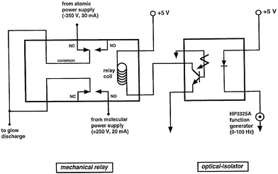 | ||
| Fig. 1 Modulation circuit for the GSGD. Both poles of the DPDT electro-mechanical relay are used to reduce the likelihood that the power supplies can short together if the relay fails. The optical isolator prevents damage to the function generator in the event of a mechanical failure. | ||
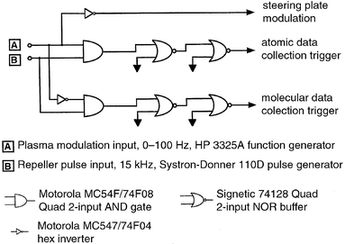 | ||
| Fig. 2 High-speed logic circuits used to trigger data collection devices during the appropriate plasma half-cycles. All input/output levels are TTL (5 V). A Systron-Donner 110D pulse generator supplies the 1 µs repeller pulse; the Hewlett-Packard 3352A frequency synthesizer/function generator drives plasma switching. The two 50 Ω output NOR buffer gates (in series) yield an exact image of the input signal, and serve to generate more distinct ‘on' and ‘off' logic levels. | ||
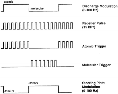 | ||
| Fig. 3 Pulse sequence employed to operate the various data collection devices (boxcar averagers, digital oscilloscope), steering plate modulation, and plasma modulation circuitry. Pulses not drawn to scale. | ||
The performance of the modulated plasma/boxcar triggering electronics was verified by simultaneously presenting a sine wave (1–1000 Hz) to both boxcars during a typical plasma switching sequence (1–100 Hz). The waveforms were accurately reproduced, indicating the ability to track signals from a transient signal generator such as the exponential-dilution cell or gas chromatograph. The logical output from the plasma modulation circuit was connected to the ‘reset' input of the boxcar, which prevented extraneous data from being sent from, for example, the atomic boxcar while the molecular boxcar was being sampled (and vice versa).
Mass spectrometer
The TOF mass spectrometer used for these experiments has been described previously2,28 and no significant instrumental modifications were required for the present study. A liquid nitrogen cold finger packed with activated alumina (grade H-152, Sigma) was installed between the first stage roughing pump and spectrometer in order to reduce background contamination from pump oil. Chemical noise was significantly reduced, but not completely eliminated, with this trap in place.The TOFMS incorporates a pair of horizontal (XY) and vertical (deflection) steering plates in order to direct the ion packet into the flight tube. A mode-specific XY steering plate potential was required for suitable ion transmission and detection. A circuit was designed in-house to modulate the steering plate potential between these two voltages. The circuit has a rise and fall time (<1 µs) which is considerably shorter than the settling time of the mechanical relay (≈5–10 ms). The pulse width and frequency of the steering plate potential corresponds exactly to the switching of the plasma and is driven by the output of a HP 3325A function generator. The amplitude of the supplemental voltage (≈−300 V) is provided by a Heathkit IP-17 power supply and is floated on the normally static steering plate potential (≈2060 V). The approximate steering plate voltages and their relationship to the plasma switching sequence are presented in the bottom portion of Fig. 3.
In contrast to the different steering plate voltages required to collect the atomic and molecular spectra, both types of data could be collected at similar ion optical voltage settings. These values represent a compromise in the best ion lens setpoints for each mode separately. Ideally, it also would be desirable to modulate each lens voltage between the optimal atomic and molecular settings.
Sample introduction
Two dynamic sample-introduction techniques were employed: a flow cell and an exponential dilutor.2Data collection
The flow cell data were collected on a 500 MHz Tektronix digital oscilloscope (Model TDS520). Two boxcar averagers (Model SR250, Stanford Research Systems) were employed to collect the spectrometric data when the exponential dilutor was employed in detection limit and linearity studies. Data were transferred from each of these devices to a MacIntosh Quadra 950 computer equipped with a NB-MIO-16-XL data acquisition board and LabVIEW (National Instruments) software. Kaleidegraph provided statistical treatment and graphical presentation of the data.Reagents and materials
All chemicals were of analytical-reagent grade or better and purchased from a variety of suppliers including Aldrich, Fisher Scientific, J.T. Baker, Mallinckrodt, and Sigma. Hamilton Model 705 gas-tight syringes were utilized for analyte introduction into the exponential dilutor. Gases were of UHP/Zero grade or better and purchased from Air Products.Results and discussion
The interface design is similar to that used in earlier experiments.2 The atomic and molecular discharge parameters are presented in Table 1. In the previous studies,2 a negative voltage was always applied to the sample-introduction plate even when the molecular spectra were collected. In the current study, the ionization mode was selected by the application of the appropriate voltage polarity to the sample inlet plate. A negative voltage was used to generate the atomic spectrum, while a positive potential yielded a molecular fragmentation pattern. The modulated discharge could be operated independently in either mode and this capability aided instrumental tuning and served as a useful plasma diagnostic. The experimental conditions associated with collecting each type of spectrum (atomic or molecular) could be separately evaluated and optimized.| Parameter | Atomic | Molecular |
|---|---|---|
| Voltage on sampler | Negative | Positive |
| Type of discharge | Abnormal | Normal |
| Current/mA | 25 | 15 |
| Voltage (dc)/V | 350 | 210 |
| Pressure/Torr | 5.50 | 5.50 |
Modulation electronics
It was found possible to modulate the source at frequencies in excess of 100 Hz by using a simple 16 pin DIP electro-mechanical relay. The relay operation became erratic above approximately 150 Hz, which set the upper switching rate. This modulation limit does not, however, reduce the usefulness of this source for conventional chromatographic applications. The relay did not suffer from arcing or shorting at the voltages and currents used in these experiments.The optimal steering plate potentials were determined empirically with the discharge operated statically in either the atomic or molecular mode while analyte vapor was swept into the plasma. The steering plate voltage used for the molecular mode of operation was ca. 200–300 V more negative than in the atomic mode. It was found possible to collect molecular signals over a wider range of steering plate potentials than in the atomic mode, suggesting that the molecular ions have a wide distribution of kinetic energies. This could be a consequence of impact ionization with electrons having a span of energies which are known to exist in the glow discharge.5,31,32 The atomic mode does not exhibit this behavior because ionization likely occurs as a result of collisions with metastable species which have well-defined energies (Penning ionization). Final tuning for the greatest signal intensity (atomic and molecular) was performed with the plasma operated in the modulated mode and with sample flowing into the discharge.
Optimization of electrode geometry
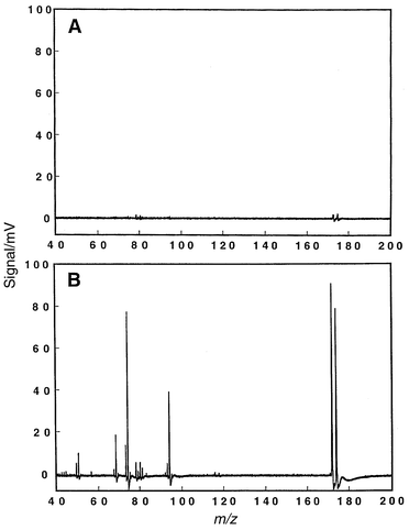
Several input-electrode geometries were tested to explore the possibility of enhancing the ionization sensitivity of the GSGD in the molecular mode. It was judged acceptable to sacrifice some atomic sensitivity in favor of the molecular sensitivity since the atomic signal was significantly greater. It was also considered important to achieve good correlation with the conventional EI mass spectra. The discharge was operated in the static mode during these studies; the findings were later substantiated during plasma modulation.Fig. 4A–C illustrate how the molecular spectrum for bromoform is influenced by changes in the GSGD electrode geometry. In Fig. 4A, a simple 3.8 cm planar electrode is employed, while Fig. 4B and C were taken with the hollow anode design described earlier. Fig. 4B and C differ in the sampling distance between the anode surface and skimmer (9 vs. 11 mm, respectively). The character of the fragmentation pattern is different for the three geometries. Fig. 4B depicts an almost equal distribution of species, whereas Fig. 4A shows a high percentage of lower molecular weight fragments. Fig. 4C compares most favorably of the three to the 70 eV EI mass spectrum for bromoform, which is provided as Fig. 4D for comparison. This geometry (hollow anode, 11 mm sampling distance) was also noted to provide good correlation with the EI spectra for other halogenated hydrocarbons, and was used in all subsequent experiments.
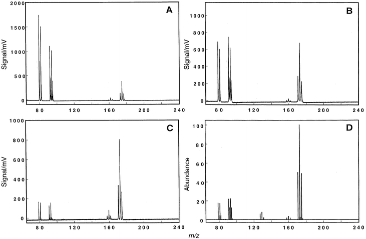 | ||
| Fig. 4 Bromoform molecular mass spectrum when different input-electrode geometries are used. Data were collected on the digital oscilloscope (1000 transients averaged); oscilloscope was triggered using the circuitry of Fig. 3. Part A depicts the spectrum obtained with the simple planar electrode design (diameter 1.50 in, surface area 1.76 in2). Parts B and C illustrate results with the hollow anode configuration. Discharge conditions: 5.50 Torr helium, 15 mA/210 V. A: Sampling distance between the input-electrode and skimmer was set to 9.0 mm. B: Sampling distance set at 9.0 mm. C: Sampling distance increased to 11.0 mm. D: Reconstructed 70 eV EI mass spectrum for bromoform provided as a comparison. Other halogenated compounds analyzed by the GSGD-TOFMS technique also produce spectra that compare favorably to those from an EI source. | ||
Several other electrode geometries were also tested (spectra not presented). Simple planar electrodes having different surface areas were examined: 11.39 cm2 (1.50 in diameter, 1.76 in2), 2.85 cm2 (0.75 in diameter, 0.44 in2), and 0.46 cm2 (0.30 in diameter, 0.07 in2). Bromoform was used as the target molecule in these studies and the plasma was not switched. The simple planar electrodes appear, in general, to produce a greater fraction of lower molecular weight species than does the hollow anode design. The overall molecular signal levels were within an order of magnitude of each other for all planar designs. The configurations that were investigated and the resulting molecular ionization sensitivities are presented in Table 2. The reference values for the molecular ions chosen for this study are also provided for comparison.17 The signals obtained during atomic ionization were noted to become smaller as the surface area of the anode was reduced. This suggests that a larger electrode generates a higher flux of active species that contributes to enhanced atomization and ionization of the sample vapor, and consequently better atomic sensitivity. Additionally, several other hollow-anode designs were investigated including those having a deeper (2 cm) cavity. A stable plasma could not be generated with these alternative designs; it appears that poor pumping and inefficient evacuation of the deeper recesses created pockets of gas which were sporadically released, resulting in an unstable plasma. The discharge described in these experiments operates differently from those previously reported.2 In earlier experiments, the helium discharge was operated solely in the static mode and molecular spectra were generated through the use of an alternative plasma gas (argon). In the current studies, atomic spectra are still generated by the application of a negative voltage to the electrode (cathode); however, producing a molecular spectrum requires that a positive potential be applied to the sample-introduction plate (anode). The atomic mode generates an abnormal discharge,2,4 which appears symmetrical, is bright pink, and contained between the cathode and the grounded skimmer.
| Signal level/mVb | |||||
|---|---|---|---|---|---|
| Surface area/in2 | Cathodea type | Spacing from anode to skimmer/mm | Br+ | CBr+ | CHBr2+ |
| a(H) Hollow cathode; (P) simple planar. bMeasured at m/z 79 (Br+), 91 (CBr+), and 173 (CHBr2+). cValues extracted from spectral tables of ref. 17. | |||||
| 1.76 | P | 9 | 1766 | 1124 | 390 |
| 1.76 | H | 9 | 701 | 764 | 693 |
| 1.76 | H | 11 | 184 | 164 | 821 |
| 0.45 | P | 9 | 2122 | 948 | 547 |
| 0.07 | P | 9 | 895 | 4055 | 612 |
| Reference valuesc | 17.5 | 21.8 | 173 | ||
The performance and appearance of the molecular discharge is different from that of the atomic system. The voltage–current curve for this discharge is presented in Fig. 5 and suggests a normal-mode of operation because the potential only increases by 15 V over the current range 10–400 mA.31,32 The geometry of the molecular cathode (the skimmer and interface cavity) is complex, in contrast to the simple cylindrical symmetry of the atomic cathode (the sampling plate with a recess). The molecular plasma is diffuse and is a light pinkish-blue. The current and voltage are similar for the two ionization modes; however, the surface area of the molecular anode exceeds that of the atomic cathode by at least a factor of ten, which will necessarily result in the production of a more diffuse and less energetic plasma. Hollow-anode discharges33–38 have been reported to exhibit similar properties to those of the molecular-mode GSGD and could provide the electrons (or metastables) responsible for molecular fragmentation and ionization. The hollow-anode discharge contains a variety of distinct zones, the identity and size of each being highly dependent on the experimental conditions. A limited amount of early literature also describes optical emission studies of molecular ions generated by EI in the GD;39–41 however, contemporary literature has primarily focused on the characterization of abnormal discharges.
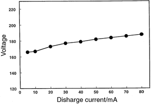 | ||
| Fig. 5 Voltage–current curve for the discharge when operated in the molecular ionization mode. A modest voltage change (15 V) is noted over the large current span (10–400 mA), which would suggest a normal mode of operation. | ||
The symmetry of the two cathodes (instrumental cavity vs. sample-introduction plate) is different; thus, simple comparisons are difficult. In the molecular mode, the instrumental cavity becomes the cathode which repels electrons and serves to accelerate, or attract, the desirable cationic species towards the grounded skimmer. In the atomic mode, the situation is different as the sample-introduction plate is now the cathode and viscous forces transfer ions and neutral species into the second vacuum stage.32
Appearance of atomic and molecular spectra
A number of halogenated hydrocarbons were examined during the course of these experiments. There are several advantages to using these compounds: most have vapor pressures high enough to enable sampling by the flow cell, very distinctive atomic and molecular spectra that facilitate experimental optimization, and they are of environmental importance. Compounds such as bromoform and chloroform are especially attractive as even a small amount of analyte will generate a large signal, thus reducing the likelihood of plasma quenching. Fig. 6A illustrates the atomic mass spectrum for bromoform obtained while the discharge is modulated at a rate of 10 Hz. A 10 Hz plasma modulation rate was chosen for this and subsequent experiments because the source is intended eventually to be used as a chromatographic detector; this rate would permit the collection of both atomic and molecular spectra for eluates. The digital oscilloscope was used to collect the data, with 1000 transients averaged per spectrum. The mass spectrum has been truncated for clarity; however, signals were also present at m/z values corresponding to hydrogen and carbon.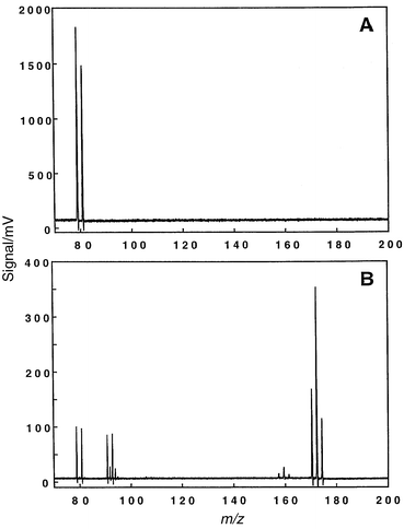 | ||
| Fig. 6 Atomic and molecular mass spectra for bromoform vapor swept into the GSGD while the plasma was modulated at 10 Hz. Data were collected on the digital oscilloscope (1000 transients averaged); oscilloscope was triggered using the circuitry of Fig. 2. A: Atomic ionization mode; discharge conditions: 5.50 Torr helium, 30 mA, 350 V. B: Molecular fragmentation mass spectrum; discharge conditions: 5.50 Torr helium, 20 mA, 250 V. | ||
Bromine has two natural isotopes (79Br+, 81Br+) which are approximately equal in abundance, a fact that does not appear to correspond with the atomic mass spectrum of Fig. 6A. Intense signals can lead to artificially low signal levels for following peaks at longer flight times, which is likely a consequence of detector blinding or fault in the preamplification circuitry. Similar artifacts are noted in both the atomic and molecular mass spectra when collecting data with the digital oscilloscope, because a larger amount of sample must be introduced into the GSGD-TOFMS for this data collection device to be useful. The isotope ratios are in accordance with expected values when sample mass flow rates are reduced, albeit at a lower signal-to-noise ratio. For example, the signal levels of Fig. 6B (m/z 79 and 81) are more than one decade lower than those of Fig. 6A, but the isotopic abundances are now in accordance with the expected ratio. This disagreement is not experienced when one employs the boxcar averagers or ion counting because lower analyte introduction rates are utilized. Disparities associated with steering plate and ion optical lens voltages are negligible.
Fig. 6B depicts the mass spectrum which was collected during the molecular-mode half cycle of the plasma. The molecular levels are about 5–10 times lower than the atomic signals. The molecular spectrum compares favorably to the conventional 70 eV17 EI mass spectrum, as depicted in Fig. 4D. Minor components at m/z 130 do not appear in the molecular GSGD mass spectrum, and it was not generally possible to view the parent ion even under gentle plasma conditions. This seems to indicate that the discharge is more energetic than conventional EI sources. However, most of the important spectroscopic features are present in the molecular GSGD spectra, which should allow comparison with spectral databases for the identification of unknown analytes. Some compounds, such as straight-chain chlorinated hydrocarbons, yield higher levels of lower m/z fragments than are found in standard EI reference spectra.
Discharge characterization
The effect of modulation rate on the overall signal level was investigated for both the atomic and molecular ionization modes; these relationships are presented in Fig. 7 for bromoform. The 79Br+ isotope was chosen for the atomic mode, while the 173CHBr2+ ion served as the molecular probe. Data were collected on the digital oscilloscope; each data point is the average of 1000 individual mass spectra. At the onset of this experiment, the atomic signal was experimentally reduced to the level of the molecular ion by de-tuning the steering plate voltage required for the atomic signal. This step was important for several reasons. First, the relative precision for each signal was monitored, a comparison that would only be fair if the signal levels were approximately equal. Second, the original atomic signal was strong enough to blind the detector, possibly biasing the molecular signal. Both the atomic and molecular signals drop in a non-linear fashion as the modulation rate increases, and the ion lens voltages could not be used to return the signals to their original levels. Similar results were noted during an independent survey of methylene chloride and trichloroethylene. The source of signal loss probably resides in the data collection step. The oscilloscope can be triggered close to, or at the end of, a plasma half-cycle, thus resulting in an artificially low signal because time is spent collecting and averaging data from the improper ionization mode. This effect becomes more problematic at higher switching rates because statistically more spectra will be collected under these compromised conditions. The oscilloscope record length was selected to be as short as possible; unfortunately, this problem could not be completely eradicated and was noticeably worse when longer data records were used. Obviously, it would be desirable only to collect data during the plasma cycle which is being investigated. An improved data system will be necessary to overcome this limitation.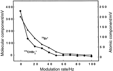 | ||
| Fig. 7 Effect of plasma modulation frequency on the atomic and molecular signals for bromoform vapor swept into the discharge from the flow cell. The helium discharge was operated at 5.50 Torr, data were collected on the digital oscilloscope, and 1000 transients were averaged. A minimum of three replicates were collected at each modulation rate. The atomic plasma was operated in the current-controlled mode (30 mA/350 V) while the molecular discharge was voltage-limited (20 mA/225 V) at a pressure of 5.50 Torr. | ||
Rapid excursions in the analyte signal occurring during an ionization cycle will not be clearly apparent in the time-averaged mass spectrum collected by the digital oscilloscope. Signal variations were probed by delaying the ion extraction step (repeller event) relative to the time at which the plasma was switched. A single mass spectrum was collected during each cycle and a number of mass spectra were averaged (at each delay time) to improve the signal-to-noise ratio. The repeller delay was incrementally advanced from the beginning to the end of an ionization cycle, and the baseline-corrected peak-height data obtained at each delay setting were then plotted. The time-variant atomic (35Cl+) signal for carbon tetrachloride is presented in Fig. 8A, while the corresponding signal for the molecular fragment ion (CCl+) is illustrated in Fig. 8B. The plasma was switched at a rate of 10.3 Hz during this study. The time required for the plasma voltage to switch from positive to negative was between 3 and 4 ms (actual) and was a function of the response time of the electro-mechanical relay, and how quickly the power supplies could ignite and stabilize the discharge. A Hewlett-Packard 5335A universal counter measured the exact time difference between the plasma switch and the repeller delay. The signals are seen to rise quickly (<1 ms), to peak, and then to decline to a steady-state plateau. The signals also are seen to decrease quickly when the ionization cycle is terminated, which can be partially attributed to the switching of the steering plates which also serves to reduce the signal. Similar behavior was observed for both the atomic and molecular signals, and verified for higher switching rates (50 Hz).
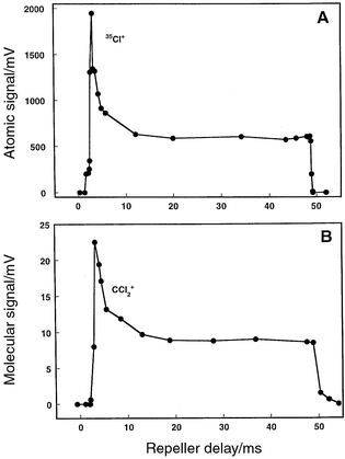 | ||
| Fig. 8 The TOF repeller was delayed with respect to the switch of the plasma, and a single mass spectrum was collected at each delay. Each mass spectrum is the average of 200 transients. The baseline-corrected peak-height value for the atomic or molecular component was then used to generate the corresponding plot. Plasma switched at 10 Hz, 5.50 Torr pressure, and carbon tetrachloride vapor introduced into the discharge. A: Atomic (35Cl+) response over the discharge period; discharge conditions: 30 mA, 350 V. B: Molecular (CCl2+) signal response over the next plasma half-cycle; discharge conditions: 15 mA, 210 V. | ||
The switched GSGD source shares some common traits with the argon microsecond pulsed21 and modulated22 glow discharge plasmas. Several transition states are known to exist in the microsecond pulsed glow discharge.21 The ‘prepeak' contains a large population of plasma-gas ions,21,22 and gaseous contaminants which have been ionized by EI.22 Argon was employed in these studies; thus, it was considered improbable that Penning ionization was responsible for ionizing the impurities which included water, carbon monoxide, and nitrogen. In the switched GSGD, analyte molecules are always present in the chamber and can be readily ionized by the helium ions and the high-energy electrons which are generated during the initial breakdown of the plasma gas.22 It has also been shown that the metastable species can persist in the plasma chamber for several milliseconds after cessation of the discharge.21,22 Thus, when the plasma is switched from the molecular to atomic mode, it is possible that some metastable species are left over from the previous cycle which can then subsequently aid in analyte ionization. The impact of metastable species on the ionization process when switching from the atomic to molecular mode could be reduced by plasma expansion, which reduces their effectiveness, thereby increasing the importance of the EI mechanism. The afterpeak, which is a common trait of other modulated discharges,21,22 is expected to be negligible because atom sputtering is not an important consideration in operation of the GSGD. Moreover, the XY steering plates are switched in concert with the plasma which would further reduce the likelihood that an afterpeak signal would be observed. The temporal resolution with which we can study the signal production and decay is currently limited by the power distribution system of the switched GSGD; however, the trends depicted in Fig. 8A and B are very similar to those reported for other pulsed glow discharge systems.
The enhanced analyte signal which is obtained immediately following the plasma switch can be advantageously employed to overcome low signal levels. Fig. 9A and B illustrate the improvements that can be realized for the molecular determination of bromofluorobenzene (BFB) at a repeller delay of 5 ms. In Fig. 9A, the digital oscilloscope was used to average 200 spectra over several molecular modulation events; the most intense peak-height is ca. 5 mV. Fig. 9B presents 200 averaged spectra for BFB; however, a single mass spectrum was collected during one ionization cycle where the repeller delay was set for optimal signal recovery. In this case, 200 ionization cycles were required to collect a single averaged mass spectrum but the signal enhancement was significant (ca. 10–30-fold). BFB is a common EI probe in mass spectrometry, and the molecular mass spectrum of Fig. 9B compares favorably to the standard 70 eV EI spectrum.17
 | ||
| Fig. 9 Molecular signal enhancement for bromofluorobenzene (BFB) that can be realized by collecting data at the optimal repeller delay as shown in Fig. 8. Plasma modulated at a rate of 10 Hz, discharge operating conditions: 15 mA/210 V, 5.40 Torr. Data collected on the digital oscilloscope; each displayed mass spectrum is the average of 200 spectra. A: Conventional triggering scheme of Fig. 2 employed to collect a time-averaged spectrum over the whole ionization cycle. B: Repeller delayed for optimal signal recovery. | ||
The effect of ‘cross-talk' was measured as a function of plasma modulation rate and found to be negligible. Cross-talk was assessed as the amount of molecular signal which could be measured during the atomic discharge period, and conversely, the atomic signal that was present during molecular ionization. The bromoform molecular spectrum naturally contains an atomic component as part of the fragmentation process; however, the ratio of atomic/molecular signal (during molecular ionization) did not change as the modulation rate was increased to a rate of 110 Hz.
Precision and temporal stability
Bromoform vapor was swept into the discharge via the flow cell, and the long-term signal stability was measured for a period of 1.25 h. The plasma modulation rate was 10 Hz for these experiments. The Tektronix digital oscilloscope was used to collect data with 5000 transients co-added for each data point and three spectra collected at each time interval. Both atomic (79Br+) and molecular (173CHBr2+) signals were monitored, as well as atomic (79Br+/81Br+) and molecular (173CHBr2+/172CHBr2+) ionic ratios. The averaged atomic signals are presented in Fig. 10A, whereas the molecular signals are illustrated in Fig. 10B. The raw atomic signal has a measured precision of 13.3% RSD, while the molecular signal exhibited somewhat less variation at 6.12% RSD. The atomic and molecular ratios, however, were considerably more precise: 1.06% RSD for the atomic and 1.61% RSD for the molecular ratio. Isotope ratio and molecular fragment ion precision values were experimentally determined to be limited by counting statistics. A benefit of the TOF design is the simultaneous extraction and analysis of the selected ion packet, which helps minimize the effects of plasma-related instabilities. The raw signal precision is of the same magnitude as previously reported for static operation of the discharge under similar conditions of sample delivery and data collection.2 These precisions are adequate for qualitative investigations of a sample. Modulation does not appear to compromise the plasma integrity, at least within the current limits of precision and for a modulation rate of 10 Hz.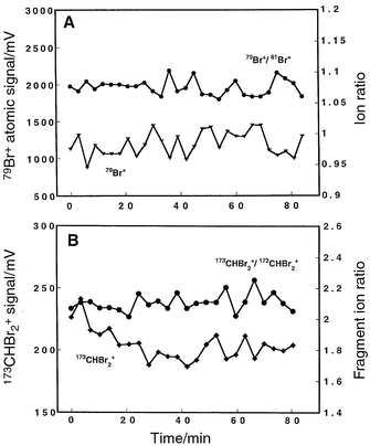 | ||
| Fig. 10 Signal stability for the atomic and molecular ionic fragments of bromoform vapor swept into the discharge via the flow cell. The plasma was switched at a rate of 10 Hz, and operated at a pressure of 5.50 Torr and 30 mA/350 V. A minimum of three replicate measurements were taken; 5000 spectra were averaged on the digital oscilloscope. Oscilloscope triggered as shown in Fig. 2. A: Atomic signal and isotope ratio (79Br+, 81Br+). The overall precision for the raw signal (79Br+) was 13.3% RSD, while the atomic ratio (79Br+/81Br+) precision was considerably better at 1.06% RSD. B: Temporal stability for the molecular fragment ions; plasma operated at 15 mA/250 V. The overall precision for the raw signal (173CHBr2+) was 6.12% RSD, while the molecular fragment ratio (173CHBr2+/172CHBr2+) precision was measured as 1.61% RSD. | ||
Short-term precision was measured from a series of seven consecutive replicate determinations of bromoform vapor, each final spectrum consisting of 5000 co-added scans. This test was completed in less than 10 min. The plasma was modulated at 10 Hz. The raw atomic (79Br+) signal and isotope ratio (79Br+/81Br+) exhibited a deviation of 7.52 and 0.232% RSD, respectively. The molecular signal (173CHBr2+) and corresponding molecular fragmentation ratio (173CHBr2+/172CHBr2+) precision was determined to be 5.41 and 0.432% RSD, respectively. The short-term precision is better (lower) than the long-term measurement. Electronic drift and fluctuations, as well as plasma anomalies such as cathodic deposition, probably compromise the figures of merit over longer time periods.
Effect of modulation rate on elemental ratios
A sample of methylene chloride vapor was swept into the discharge via the flow cell, and the elemental ratio (35Cl+/12C+) was monitored as the modulation rate was increased from 0.2 to 100 Hz. Data were collected on the Tektronix digital oscilloscope, with 1000 scans co-added for each measurement; three replicates were collected at each switching frequency. The elemental ratios are constant across this span of switching rates; no systematic bias is observed. The signals become weaker as the modulation rate goes up (see Fig. 7), which will necessarily introduce more scatter (less precision) in the measured ratio. The line exhibits a non-zero slope (m = −0.0008); however, this deviation should not compromise the use of this technique for qualitative (or semi-quantitative) investigations. Reduced precision resulting from lower signal levels could also contribute to the gradual downward slope of this line. One benefit of the TOF spectrometer design is that it simultaneously extracts analyte ions from the sample beam, which provides a high level of precision in ratio measurements. This ratioing fidelity helps compensate for signal or plasma instability. The use of higher modulation frequencies will facilitate coupling this source with high-performance separation techniques that produce peak widths of 1 s or less.Linear range and detection limits
The exponential dilution system and boxcar averagers were employed to test the linear range and detection limits of the GSGD-TOFMS combination. An aliquot of sample vapor was manually introduced into the exponential dilutor and the signal from the boxcar averager was transferred into the Q950 computer by means of LabVIEW® software. The sample vapor aliquot was typically between 1 and 20 µl; the particular amount was chosen to avoid detector saturation while staying within the linear range of the detection system.Even though the plasma duty cycle is reduced by half when both atomic and molecular mass spectra are required, the high spectral generation rate permits acquisition of a large number of spectra, which makes tracking changing signals (as from the exponential dilution cell) still possible. A plasma modulation rate of 50 Hz allows the collection of 150 spectra during either the atomic or molecular half-cycle. As the modulation rate increases, the number of mass spectra which are available to average during any half-cycle decreases. Large numbers of spectra can be collected at very low switching rates (1 Hz for example); however, it could be difficult then to track a rapidly changing signal accurately. In these experiments, data were collected at a switching rate of 10 Hz because this system will ultimately be coupled with a gas chromatograph. It is expected that, at this switching rate, chromatographic fidelity can be retained for most capillary and packed column separations.
Complete calibration graphs were generated in less than 3 min, with over 200 calibration points being collected for each analytical run. The boxcar averager was set for 30 averages per point with a 25 ns gate width. A high gas flow rate into the exponential dilutor was employed to reduce the likelihood of air back-flushing into the discharge. The rapid washout time, in addition to the elevated temperature, reduces the chance of sorption on the cell walls or transfer tubing.
The atomic and molecular detection limits (at 3σ) for a variety of analytes introduced into the flow cell are presented in Table 3. The atomic values are for the element (halogen) and the molecular numbers are for the compound. A linear calibration graph of greater than two orders of magnitude was realized with the dilution cell. The correlation of fit for all linearly regressed data exceeded 0.99 (R). Several different m/z species are typically available for the molecular quantification studies. A molecular ion having a flight-time close to its atomic counterpart (and also one which offered about the same signal level as the most abundant fragment ion) was chosen in order to minimize steering plate bias.27,28,42,43 At least three replicate injections were performed for each detection limit measurement. Not all analytes were sufficiently volatile to permit analysis by this technique. A series of four consecutive chlorohexane replicates was analyzed; a precision of 5.46% RSD was realized for the atomic measurements and 7.73% RSD for the molecular detection studies. The atomic detection limits for the modulated source are comparable to those for static operation.2 The small differences can be attributed to experimental imprecision associated with day-to-day operation of the instrument and the need to operate the ion lenses under slightly compromised conditions.
| Compound | Atomic detection limit | Molecular detection limit |
|---|---|---|
| aDetection limits expressed in units of pg s−1 and calculated at 3σ; atomic values are for the element (halogen), molecular values are for the compound. bAnalytes introduced via exponential-dilution cell. cValues in parentheses represent the m/z values used for quantification. | ||
| Chloroform | 36 (35)c | 148 (83)c |
| Carbon tetrachloride | 24 (35) | 184 (117) |
| Methylene chloride | 91 (35) | 197 (84) |
| Trichloroethylene | 98 (35) | 247 (95) |
| 1-Chlorohexane | 40 (35) | 122 (27) |
| Bromoform | 3.9 (79) | 14 (93) |
| 1,2-Dibromoethane | 52 (79) | 44 (27) |
The atomic detection limits for the switched GSGD are compared with those for several other plasma-based ionization sources in Table 4.7,44–50 The ion source, support gas, and detection method have also been included for comparison. Caution must be exercised when attempting to compare the figures of merit for systems employing different ionization sources, various detection strategies (optical emission vs. mass spectrometric), and dissimilar sample inlet systems (gas chromatographic vs. exponential dilution). The values presented in this paper compare favorably to those of the other analytical systems; however, plasma switching has slightly compromised the detection limits for the GSGD.2 The microwave-induced plasma (MIP) is a popular elemental ionization source, and when coupled with mass spectrometry, provides one of the best methods for the determination of halogens.24
| Reference | Sourcea | Chlorineb | Bromineb |
|---|---|---|---|
| aAr = Argon; He = helium; MIP = microwave-induced plasma; ICP = inductively coupled plasma; MPT = microwave plasma torch; OES = optical emission spectrometry; MS = mass spectrometry; AAS = atomic absorption spectrometry; bDetection limits expressed in units of pg s−1. cNR = not reported. | |||
| This work | Switched-GSGD | 25–100 | 4–52 |
| 24 | He-MPT-MS | 0.015 | 0.014 |
| 49 | He-rf GD-OES | 1.1 | 0.9 |
| 44 | He-MIP-OES | 5 | <10 |
| 47 | He-MIP-OES | 9.2 | 0.92 |
| 46 | He-MIP-OES | 25 | 12 |
| 48 | He-MIP-OES | 43 | 33 |
| 45 | He-MIP-AAS | 80 | NRc |
| 46 | He-ICP-OES | 800 | 1000 |
| 7 | He-GSGD-OES | 5000 | NRc |
| 46 | Ar-ICP-OES | 19000 | 53000 |
Chemical speciation based on elemental ratios
A variety of analytical techniques have been used to determine empirical formulae as a means of differentiating chemical compounds.24,51–55 The simplicity of the GSGD interface, and its inherent capability to generate elemental mass spectra, makes this source an attractive speciation tool.A number of volatile chlorinated hydrocarbons were introduced into the GSGD interface via the flow cell. These particular analytes were chosen for the wide range of halogen-to-carbon ratios that they represented. The spectrometric data were collected on the Tektronix digital oscilloscope, triggered on the atomic modulation pulse. The baseline-corrected peak-height data for 35Cl+ and 12C+ were manually calculated after being imported into Kaleidegraph. Good correlations have also been found with peak areas although these data are not presented here. At least three separate measurements were made for each analyte, each representing 1000 averaged spectra. The measured 35Cl+/12C+ ratios for a series of halogenated hydrocarbons are compared with the true values in Fig. 11. These data have not been corrected for isotopic abundances. An excellent correlation (R = 0.995) is found over the range of ratios tested.
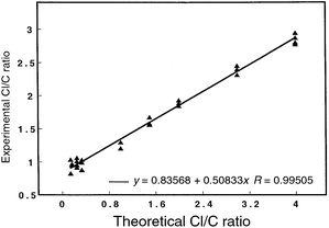 | ||
| Fig. 11 Measured elemental ratios (35Cl+/12C+) for chlorinated hydrocarbons obtained from the atomic mass spectrum of the modulated plasma (10 Hz). Peak heights were used to calculate the ratio; peak areas were also found to correlate but are not reported here. Data not corrected for isotopic abundance. Sample vapor swept into the GSGD using the flow-cell arrangement. Data were collected on the digital oscilloscope, as triggered by the circuit of Fig. 2. Plasma operated at 5.50 Torr helium; 30 mA/350 V. A minimum of three replicate measurements were performed for each analyte with 1000 transients averaged per spectrum. The following compounds (and theoretical Cl∶C ratios) were tested: carbon tetrachloride (4∶1), chloroform (3∶1), methylene chloride (2∶1), trichloroethylene (3∶2), chloropropane (1∶3), 2-chloro-2-methylpropane (1∶4), 2-chlorobutane (1∶4), 1-chlorohexane (1∶6). | ||
The non-unity slope of the calibration line indicates an experimental bias, which could be the result of several different factors. The circuit employed to deflect away the support-gas ions (4He+, 4He2+) might inadvertently mask some of the higher m/z species (i.e., carbon) as well, which would artificially diminish the analyte signal and affect the calculated ratio. Mass bias associated with the spectrometer steering plates could also contribute to this disparity.28,42,43 Quenching of the plasma could result from plasma overloading, thus diminishing the power available for atomization and ionization. Plasma loading could potentially alter the ionization/excitation characteristics of the discharge; similar effects have been noted to influence elemental ratio measurements when other ionization sources have been employed for similar types of analyses.55
Conclusions
A modulated GSGD has been developed as an ionization source for mass spectrometry. It is possible to switch rapidly between atomic and molecular modes of ionization; signals were measured on a digital oscilloscope at switching rates up to 100 Hz. The ionization mode was selected by altering the polarity of voltage applied to the sample-introduction plate. Switching the polarity alternates the discharge between the abnormal (atomic) and normal (molecular) modes of ionization. The molecular mode generated mass spectra which strongly resemble standard 70 eV EI reference spectra. It was possible to differentiate between a variety of chlorinated compounds by comparison of the theoretical and experimental elemental ratios while the discharge was being modulated at 10 Hz. Detection limits (atomic) and precision for the modulated source (when the exponential-dilution cell and boxcar averagers are employed) are approximately the same as those measured during static plasma operation. In the future, this source will be coupled to a capillary column gas chromatograph and the figures of merit determined.Acknowledgements
Funding was provided, in part, by the Department of Energy through grant DE-FG02-98ER14890. Fellowship support for J.P.G. was provided by Eli Lilly & Co. The steering plate modulation circuit was designed and built by Andrew Alexander of the Electronic Instrument Services (EIS) group at Indiana University. The Mechanical Instrument Services (MIS) group constructed the various cathodes used in these studies.References
- W. W. Harrison, J. Anal. At. Spectrom., 1992, 7, 75 RSC.
- J. P. Guzowski, J. A. C. Broekaert, S. J. Ray and G. M. Hieftje, J. Anal. At. Spectrom., 1999, 14, 1121 RSC.
- J. A. C. Broekaert, R. Pereiro, T. K. Starn and G. M. Hieftje, Spectrochim. Acta, Part B, 1993, 48, 1207 CrossRef.
- T. K. Starn, R. Pereiro and G. M. Hieftje, Appl. Spectrosc., 1993, 47, 1555 Search PubMed.
- K. R. Marcus, Glow Discharge Spectroscopies, Plenum Press, New York, 1993. Search PubMed.
- B. Chapman, Glow Discharge Processes: Sputtering and Plasma Etching, Wiley, New York, 1980. Search PubMed.
- R. Pereiro, T. K. Starn and G. M. Hieftje, Appl. Spectrosc., 1995, 49, 616 Search PubMed.
- CRC Handbook of Chemistry and Physics, ed. R. C. Weast, CRC Press, Boca Raton, FL, 59th edn., 1978. Search PubMed.
- A. Ben-amar, G. Erez, S. Fastig and R. Shuker, Appl. Opt., 1984, 23, 4529 Search PubMed.
- G. Berthon, Coord. Chem. Rev., 1996, 149, 241 CrossRef CAS.
- J. A. Liyanage, D. M. Taylor and D. R. Williams, Chem. Speciat. Bioavail., 1996, 8, 45 Search PubMed.
- A. K. Shrivastava, Rev. Anal. Chem., 1995, 14, 143 Search PubMed.
- Chemical Speciation in the Environment, ed. A. M. Ure and C. M. Davidson, Blackie, Glasgow, 1995. Search PubMed.
- P. Gardiner, J. Anal. At. Spectrom., 1988, 3, 163 RSC.
- P. Quevauviller, J. Anal. At. Spectrom., 1996, 11, 1225 RSC.
- L. A. Ellis and D. J. Roberts, J. Chromatogr. A, 1997, 774, 3 CrossRef CAS.
- Atlas of Mass Spectral Data, ed. E. Stenhagen, S. Abrahamsson and F. W. McLafferty, Interscience, New York, 1969. Search PubMed.
- Eight Peak Index of Mass Spectra, The Mass Spectrometry Data Centre, Royal Society of Chemistry, Nottingham, 3rd edn., 1983. Search PubMed.
- G. M. Hieftje, Anal. Chem., 1985, 57, 256A CAS.
- M. W. Borer and G. M. Hieftje, Spectrochim. Acta. Rev., 1991, 14, 463 Search PubMed.
- J. A. Klinger, C. M. Barshick and W. W. Harrison, Anal. Chem., 1991, 63, 2571 CrossRef.
- F. L. P. C. King, Anal. Chem., 1993, 65, 735 CrossRef CAS.
- P. P. Mahoney, J. P. Guzowski, S. J. Ray and G. M. Hieftje, Appl. Spectrosc., 1997, 51, 1464 Search PubMed.
- B. W. Pack, J. A. C. Broekaert, J. P. Guzowski and G. M. Hieftje, Anal. Chem., 1998, 70, 3957 CrossRef CAS.
- M. J. Heintz, J. A. C. Broekaert and G. M. Hieftje, Spectrochim. Acta, Part B, 1997, 52, 579 CrossRef.
- P. P. Mahoney, S. J. Ray and G. M. Hieftje, Appl. Spectrosc., 1997, 51, 16A Search PubMed.
- D. P. Myers, G. Li, P. Yang and G. M. Hieftje, J. Am. Soc. Mass Spectrom., 1994, 5, 1008 CrossRef CAS.
- D. P. Myers, G. Li, P. P. Mahoney and G. M. Hieftje, J. Am. Soc. Mass Spectrom., 1995, 6, 411 CrossRef.
- E. L. Inman, E. Voigtman and J. D. Winefordner, Appl. Spectrosc., 1982, 36, 99 Search PubMed.
- J. A. Fowlis and R. P. W. Scott, J. Chromatogr., 1963, 11, 1 CrossRef.
- J. A. C. Broekaert, J. Anal. At. Spectrom., 1987, 2, 537 RSC.
- W. W. Harrison and B. L. Bentz, Prog. Anal. Spectrosc., 1988, 11, 53 Search PubMed.
- V. Miljevic, Rev. Sci. Instrum., 1984, 55, 931 CrossRef CAS.
- V. I. Miljevic, Rev. Sci. Instrum., 1990, 61, 312 CrossRef CAS.
- V. I. Miljevic, J. Appl. Phys., 1986, 60, 4109 CrossRef CAS.
- V. I. Miljevic, J. Appl. Phys., 1986, 59, 676 CrossRef CAS.
- V. I. Miljevic, Rev. Sci. Instrum., 1992, 63, 2619 CrossRef CAS.
- B. E. Ballou, D. L. Styris and J. M. Harnly, J. Anal. At. Spectrom., 1988, 3, 1141 RSC.
- H. Schuler and L. Reinbeck, Z. Naturforsch., Teil A, 1950, 5, 657 Search PubMed.
- H. Schuler, Spectrochim. Acta, 1950, 4, 85 CAS.
- H. Schuler and L. Reinebeck, Spectrochim. Acta, 1954, 6, 288 CrossRef CAS.
- M. Guilhaus, J. Mass Spectrom., 1995, 30, 1519 CAS.
- J. Coles and M. Guilhaus, Trends Anal. Chem., 1993, 12, 203 CrossRef CAS.
- C. S. Cerbus and S. J. Gluck, Spectrochim. Acta, Part B, 1983, 38, 387 CrossRef.
- C. Schnurer-Patschan and K. Niemax, Spectrochim. Acta, Part B, 1995, 50, 963 CrossRef.
- S. K. Chan and A. Montaser, Spectrochim. Acta, Part B, 1987, 42, 591 CrossRef.
- A. H. Mohamad, J. T. Creed, T. M. Davidson and J. A. Caruso, Appl. Spectrosc., 1989, 43, 1127 Search PubMed.
- S. Estes, P. C. Uden and R. M. Barnes, Anal. Chem., 1981, 53, 1829 CrossRef CAS.
- S. Pedersen-Bjergaard and T. Greibrokk, Anal. Chem., 1993, 65, 1998 CrossRef CAS.
- Sac-Weon Roh, Yoo Hee-Soo and Yong-Nam Pak, Bull. Korean Chem. Soc., 1995, 16, 1023 Search PubMed.
- P. C. Uden, in Element-Specific Chromatographic Detection by Atomic Emission Spectroscopy, ed. P. Uden, ACS Symposium Series, American Chemical Society, Washington, DC, 1992, vol. 479, p. 350. Search PubMed.
- J. F. Camuna-Aguilar, R. Pereiro-Garcia, J. E. Sanchez-Uria and A. Sanz-Medel, Spectrochim. Acta, Part B, 1994, 49, 545 CrossRef.
- R. A. Heppner, Anal. Chem., 1983, 55, 2170 CrossRef CAS.
- J. J. Sullivan and B. D. Quimby, J. High Resolut. Chromatogr. Commun., 1989, 12, 282 Search PubMed.
- J. E. Freeman and G. M. Hieftje, Spectrochim. Acta, Part B, 1985, 40, 653 CrossRef.
| This journal is © The Royal Society of Chemistry 2000 |