Novel butterfly-shaped organic semiconductor and single-walled carbon nanotube composites for high performance thermoelectric generators†
Lai
Wei
ab,
Hongfeng
Huang
a,
Chunmei
Gao
 c,
Danqing
Liu
 *a and
Lei
Wang
 *ab
*ab
aShenzhen Key Laboratory of Polymer Science and Technology, College of Materials Science and Engineering, Shenzhen University, Shenzhen, 518060, China. E-mail: dqliu@szu.edu.cn; wl@szu.edu.cn
bKey Laboratory of Optoelectronic Devices and Systems of Ministry of Education and Guangdong Province, Shenzhen University, Shenzhen 518060, China
cCollege of Chemistry and Chemical Engineering, Shenzhen University, Shenzhen 518060, China
First published on 19th January 2021
Abstract
Herein, a series of novel butterfly-shaped small-molecule organic semiconductors (OSCs) have been designed, synthesized and complexed with single-walled carbon nanotubes (SWCNTs) as p-type thermoelectric materials. The butterfly-shaped molecules exhibit curved molecular structures, which tune their frontier molecular orbitals and increase their interactions with SWCNTs. A systematic study shows that the composites based on butterfly-shaped OSCs exhibit significantly improved thermoelectric performances compared with that of the composite based on the analoguous planar OSC. The enhanced thermoelectric performances are attributable to the higher activation energy, improved doping level and charge transport process between the organic molecules and SWCNTs. The butterfly-shaped OSC and SWCNT composite opens up a new avenue for the design of thermoelectric materials and devices.
New conceptsOrganic semiconductors (OSCs) are promising to be the next generation of thermoelectric materials due to their unique advantages, such as low cost, high mechanical flexibility, low thermal conductivity, and low toxicity. Control of the molecular structure of organic semiconductors is critical for optimizing the performance of organic-based thermoelectrics. Unlike the widely employed planar-core-based p-type OSCs, we herein showcase a series of novel butterfly-shaped OSCs by contorting the pentacenone/anthrone cores with steric substitutions, which brings higher power factors up to 312 μW m−1 K−2 for thermoelectric composites of OSC/SWCNT compared with that of the composite based on planar OSC. The corresponding thermoelectric generators exhibit a large output voltage up to 16.6 mV and output power up to 2.08 μW under a 31 K temperature gradient. The results set a new record for p-type thermoelectric composites based on small-molecule OSCs, indicating that curved butterfly-shaped OSC and SWCNT composites are promising thermoelectric materials and open a new approach for the design of thermoelectric materials and devices. |
1. Introduction
Thermoelectric (TE) materials can realize direct conversion between thermal energy and electric energy, and have broad application prospects in waste energy utilization, energy saving and emission reduction.1,2 Thermoelectric energy conversion efficiency is usually evaluated by the figure of merit (ZT): ZT = S2σT/κ, where S is the Seebeck coefficient or thermopower, σ is the electrical conductivity, T is the temperature, and κ is the thermal conductivity. Because the organic materials intrinsically possess low thermal conductivities in the range of 0.1–1 W m−1 K−1, the thermoelectric power factor, PF = S2σ, is often used instead of ZT to compare the organic thermoelectric performance of different materials. The thermoelectric efficiency can be improved through the optimization of the Seebeck coefficient and electrical conductivity.3 However, both the electrical conductivity and Seebeck coefficient are interrelated as a function of carrier concentration n.3 Generally, the electrical conductivity (σ) is proportional to the carrier concentration (n) and the charge carrier mobility (μ) through the equation σ = neμ, where e is the elementary charge. The Seebeck coefficient represents the entropy of a carrier with unit charge, which is negatively correlated with carrier concentration as S = 8π2kB2m*T(π/3n)2/3/(3eh2), where kB is the Boltzmann constant, h is the Planck constant and m* is the density of states effective mass. In the hopping transport neglecting the electron correlation effects, the Seebeck coefficient is proportional to the activation energy Ea (Ea = EF − Ev), and can be written as ,4 where kB is the Boltzmann constant, EF is the Fermi level energy, E is the energy level occupied by the carrier, T is the temperature, and σ is the electrical conductivity
  . If the carrier only transports in the valence band, the Seebeck coefficient is given by S = (kB/q)[(EF − Ev)/kBT] + Av,5,6 where Ev is the valence band edge, and Av is a constant. At low carrier concentration with EF − Ev ≫ kBT, Av is negligibly small and the Boltzmann distribution is justified. Obviously, Seebeck coefficients largely increase with decrease in carrier concentration and increase of the activation energy.
Recently, great progress has been made on organic conjugated polymer-based TE materials owing to their low thermal conductivity, easy synthesis and processing, abundance and environmentally friendliness, some of which have displayed high PF values approaching those of traditional inorganic materials.7–11 Compared with polymer thermoelectric materials, organic small molecules possess the merits of exact structure and various derivation, which aids the exploration of their structure–property relationship.12 However, organic small molecules also suffer from poor film-forming properties, and low mechanical properties and electrical conductivity due to their small molecular weight and low conjugated degrees. Organic semiconductors are usually complexed with single-walled carbon nanotubes (SWCNTs) as TE materials to improve the mechanical properties and electrical conductivity. SWCNTs have been utilized as TE materials owing to their unique properties, such as high conductivity, low weight density, and flexibility.9,10 An additional advantage is that they possess an extremely large surface area that allows for the efficient adsorption of substances, and therefore greatly enhances the TE performance. This enhanced performance is evidenced by an efficient charge transfer and interactions through carbon nanotubes and adsorbed substances. p-Type SWCNT/polymer-based TE materials have been well studied and reported.13–15 In contrast, only a limited number of p-type TE materials involving organic small molecule scaffolds have been developed,16–23 which lags far behind that of polymers. To date, few OSC/SWCNT composite films manifest a p-type behaviour with PF values higher than 300 μW m−1 K−2 at room temperature, most of which are still in a dilemma between the electrical conductivity and the Seebeck coefficient. For instance, Yin et al.18 reported four p-type OSCs based on planar pyrene cores as the conjugated-backbone, in which the TCzPy-based SWCNT composite film with a hybrid ratio of 1![[thin space (1/6-em)]](https://www.rsc.org/images/entities/char_2009.gif) :
:![[thin space (1/6-em)]](https://www.rsc.org/images/entities/char_2009.gif) 1 exhibited an 152% enhancement of Seebeck coefficient and a 77% reduction of electrical conductivity compared to pristine SWCNTs, resulting in a higher PF over 110 μW m−1 K−2. Other TE materials based on OSC/SWCNT composites are reported including porphyrin derivatives,16,17 1,3,6,8-tetrakis(3,6-di-tert-butyl-9H-carbazol-9-yl)pyrene,18 thieno[3,4-b]pyrazine derivatives,20 copper phthalocyanine derivatives,19,21 2,7-dioctyl[1]benzothieno[3,2-b][1]benzothiophene,22 and copper-phenylacetylide.23 However, to the best of our knowledge, most of these small-molecule OSCs for TE materials are based on planar conjugated molecules, and few of them are used for thermoelectric generator applications.
1 exhibited an 152% enhancement of Seebeck coefficient and a 77% reduction of electrical conductivity compared to pristine SWCNTs, resulting in a higher PF over 110 μW m−1 K−2. Other TE materials based on OSC/SWCNT composites are reported including porphyrin derivatives,16,17 1,3,6,8-tetrakis(3,6-di-tert-butyl-9H-carbazol-9-yl)pyrene,18 thieno[3,4-b]pyrazine derivatives,20 copper phthalocyanine derivatives,19,21 2,7-dioctyl[1]benzothieno[3,2-b][1]benzothiophene,22 and copper-phenylacetylide.23 However, to the best of our knowledge, most of these small-molecule OSCs for TE materials are based on planar conjugated molecules, and few of them are used for thermoelectric generator applications.
Butterfly-shaped organic semiconductors24–28 have been reported for organic electronic applications. For instance, Nuckolls's group synthesized a novel contorted dibenzotetrathienocoronenes (c-DBTTCs), which display molecular flexibility and tunable supramolecular self-assembly properties in the solid state by shifting molecular conformations. These contorted molecules can adopt up-down or butterfly conformations and form co-crystals with electron acceptors including planar TCNQ and spherical C60 molecules.28 This study indicates that contorted molecules hold great potential for creating geometrically complementary interfaces and nanostructures with non-planar C60 or carbon nanotubes. Butterfly-shaped molecules have also found applications in organic field effect transistors (OFETs) and organic light-emitting diodes (OLEDs).29–31 Theoretical investigations of butterfly-shaped tetraaryl pyrenes have been reported showing promising application as p-type or n-type organic semiconductors.24 This study demonstrates that introducing different substituents is able to modify the geometric structures, crystal packing motif and intermolecular interactions of the butterfly molecules, leading to entirely different charge carrier mobilities.
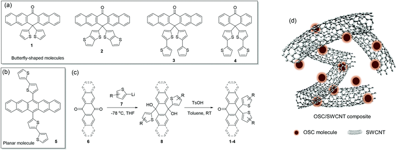
Herein, novel butterfly-shaped molecules 1–4 (Scheme 1a) with different core units and side chains are designed and complexed with SWCNT as p-type thermoelectric materials. This design approach is guided by the following consideration: (a) the π-conjugated structure is selected as the molecular backbone due to the excellent intrinsic mobility; (b) the carboxy group is introduced into the peri-position of the structure in order to introduce hydrogen bonds and obtain π–π stacking or a lamellar structure in the solid state; (c) thienyl moieties are introduced into the peri-position to improve solubility, extend π-electron delocalization and construct a steric butterfly conformation on their backbones, which are beneficial for interactions with SWCNTs. Meanwhile, the analogue of planar molecule 5 is designed for comparison (Scheme 1b). The butterfly-shaped molecules exhibit different frontier energy levels and enhanced interactions with SWCNTs compared with the planar molecule 5, resulting in higher Seebeck coefficients and electrical conductivities in the OSC/SWCNT composites. Consequently, the 2/SWCNT composite exhibits excellent TE performances with the maximum power factor of 312 μW m−1 K−2 at 350 K, which is the highest PF value for the reported p-type small-molecule OSC/SWCNT composites to the best of our knowledge. The corresponding TE module consisting of ten p legs generates a large output voltage of 16.6 mV and output power of 2.08 μW under a 31 K temperature gradient.
2. Results and discussion
2.1 Synthesis, crystal structures and electronic structures
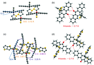
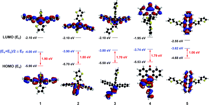
The butterfly-shaped molecules 1–4 are synthesized through two steps as shown in Scheme 1c: the reaction between pentacenone/anthrone 6 and organolithiums 7 to prepare diols 8, and the rearrangement32 of diols under strong acid to afford the asymmetric structures of compounds 1–4 in moderate yields. The planar molecule 5 has been reported as a stable and soluble organic semiconductor;33 while compounds 2, 3, and 4 have not been reported before. All the intermediates and target products are purified by column chromatography and successive recrystallization. The accurate structural information of these compounds is confirmed by 1H-NMR and 13C-NMR spectroscopies. Single crystals of 1 and 2 are grown from a mixture solution of chlorobenzene and n-hexane, while the crystals of 3, 4 and 5 obtained with the same method had low quality. As is shown in Fig. 1, molecules 1 and 2 adopt a butterfly-shaped conformation, which is dictated by H-bonds, sulfur–sulfur interactions and π-stackings. The thienyl groups are essentially perpendicular to the acene planes owing to steric interactions with the peri-disposed C–H in the pentacenone backbone. Notably, the pentacenone backbone of 1 is contorted with a naphthyl–naphthyl dihedral angle of 12.0° because of the steric thienyl substitutions (Fig. 1a). The introduction of different thienyls also greatly affects the packing structures. As shown in Fig. 1b, neighboring π-stacking of 1 is separated by hydrogen bonds and sulfur–sulfur interactions, which could enhance the intermolecular interactions and contribute to the transfer integrals of holes.24 Therefore, molecules of 1 are packed in a brickwork arrangement as viewed along the long axis of pentacenone without obvious π–π stacking. However, by replacing thienyl groups with much more steric thienothienyl substitutions, the naphthyl–naphthyl dihedral angle for compound 2 is increased to 33.4° (Fig. 1c). The sulfur atoms are disordered in the crystal structure. Meanwhile, H-bonds and sulfur–sulfur interactions are also shown in the crystal structure of 2 (Fig. 1d). Additionally, due to the much more steric hindrance and stronger intermolecular interactions induced both by the peripheral thienyls and carbonyl groups, the compound 2 adopts dimer stacking with a π–π distance of 3.96 Å and edge-to-face distance of 3.20 Å in the dimers, which are beneficial for efficient charge transport and high carrier mobility.34 These results demonstrate that introducing different “butterfly wing” like substitutions and carboxy groups generally disrupts the planarity of the central pentacenone unit and alters the intermolecular interactions.To better understand the electronic structures of these molecules, the frontier molecular orbitals of 1–5 are calculated by density functional theory (DFT) at the B3LYP/6-31G(d) level using the Gaussian 03 package (Fig. 2). The lowest unoccupied molecular orbitals (LUMOs) of 1–5 are effectively confined on the π-delocalization of the central pentacenone/anthrone units. Meanwhile, the highest occupied molecular orbitals (HOMOs) of 1 and 5 are mainly scattered over the pentacenone units. However, the HOMOs of 2–4 are delocalized mainly over the two side thiophene substituents due to the contorted pentacenone/anthrone backbone and larger conjugate systems of thiophene substituents. In contrast, the HOMOs of 1 and 5 are mainly scattered over the pentacene units due to the more planar molecular structures. For an intrinsic organic semiconductor, the HOMO and LUMO levels form the valence band (Ev) and conduction band (Ec), respectively, and the Femi levels (EF) are located near the middle of the bandgap (EF ≈ (Ev + Ec)/2) and gradually approach the Ev for p-type doping.34 In this respect, appropriate bandgap (Eg) and HOMO levels for p-type charge transport are essential for TE materials, since the carrier concentration strongly depends on the activation energy Ea (Ea = EF − Ev). The calculated HOMO levels and Eg of these OSCs are presented in Fig. 2, and all these compounds reveal adequate HOMO levels (ca. −4.68 to −5.90 eV) for interacting with the EF of SWCNT (EF = −4.91 eV).35 Noticeably, introducing different thienyl units to the pentacenone core will definitely increase the HOMO energies (from −5.9 eV to −5.5 eV) and narrow their activation energy (from 1.90 eV to 1.70 eV). The intrinsic activation energy of 5 is smaller than that of the butterfly-shaped molecules. The intrinsic activation energy of butterfly molecules 1–4 matches well with the results of their Seebeck coefficients as discussed later. These results imply that introducing different substituents to the molecular backbone will greatly affect the electron distributions and energy levels of frontier molecular orbitals.
2.2 Thermoelectric properties
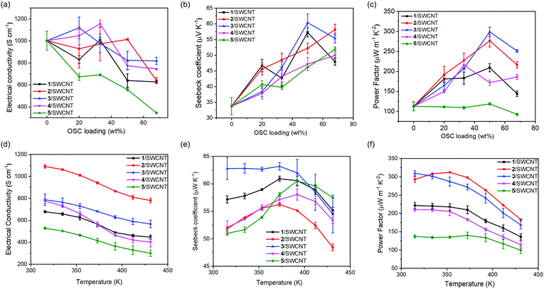
To evaluate the potential of the thermoelectric conversion capabilities of these OSCs, composite films incorporated with different amounts of SWCNTs are prepared. The polymorphism of the butterfly-shaped OSCs in the composite films is quite similar to that in single crystals as suggested by the XRD study (Fig. S8 in the ESI†). The 1/SWCNT composite film exhibited a diffraction peak at 2θ = 14.5°, which corresponded to the reflection of the (022) plane in the single crystal structure. The 2/SWCNT composite film exhibited a diffraction peak at 2θ = 14.6°, which corresponded to the reflection of the (1![[1 with combining macron]](https://www.rsc.org/images/entities/char_0031_0304.gif) 1) plane in the single crystal structure. This result indicates that complexing with SWCNT would not change the packing structure of the OSC molecules. Fig. 3a–c exhibits the σ, S and PF as a function of OSC loading in the composite films and the detailed comparisons of the performance are listed in Table S1 (ESI†). As shown in Fig. 3a, all four butterfly-shaped OSCs 1–4 display slightly increased electrical conductivity with increasing the OSC loading from 0% to 33%, probably due to the charge-transfer interactions between OSCs and SWCNTs. However, there is a decrease of electric conductivity with increasing OSC loading from 50% to 66%, probably because a large amount of OSCs interrupt the charge transport path through SWCNTs. For the planar moelcule 5 and SWCNT composite films, the electrical conductivity experienced a dramatic decrease, indicating less interactions between 5 and the SWCNTs. These results suggest that carbonyl groups and the thienyl substitutions in molecules 1–4 are able to increase the interactions between SWCNTs and OSCs.
1) plane in the single crystal structure. This result indicates that complexing with SWCNT would not change the packing structure of the OSC molecules. Fig. 3a–c exhibits the σ, S and PF as a function of OSC loading in the composite films and the detailed comparisons of the performance are listed in Table S1 (ESI†). As shown in Fig. 3a, all four butterfly-shaped OSCs 1–4 display slightly increased electrical conductivity with increasing the OSC loading from 0% to 33%, probably due to the charge-transfer interactions between OSCs and SWCNTs. However, there is a decrease of electric conductivity with increasing OSC loading from 50% to 66%, probably because a large amount of OSCs interrupt the charge transport path through SWCNTs. For the planar moelcule 5 and SWCNT composite films, the electrical conductivity experienced a dramatic decrease, indicating less interactions between 5 and the SWCNTs. These results suggest that carbonyl groups and the thienyl substitutions in molecules 1–4 are able to increase the interactions between SWCNTs and OSCs.
The Seebeck coefficients of all the composite films are positive, confirming that p-type electrical transport is dominant. Noticeably, the S values dramatically increase with increasing the OSC loading (Fig. 3b). This is presumably because of the energy filtering effect that organic small molecules attached to SWCNT selectively prevent the passage of low-energy carriers, leading to increases in the mean carrier energies and Seebeck coefficients.36 However, the excess 1 or 3 (up to 66% loading) may induce aggregation, adversely affecting the monodispersity of the SWCNTs and therefore decreasing the Seebeck coefficient. Among these samples, the composite film with planar molecule 5 has lower S value than other composite films partially due to its lower activation energy Ea, and the 3/SWCNT composite film with 50% OSC loading possesses the highest Seebeck coefficient value up to 61.3 μV K−1. These results indicate that contorted structures of OSC molecules of 1–4 generally result in enlarged activation energy, leading to higher Seebeck coefficients compared with that of the planar molecule 5. Consequently, the power factors of the composite films are calculated by the determined values of S and σ as shown in Fig. 3c. The optimized PFs of these composite films at room temperature are 216.6 μW m−1 K−2, 287.8 μW m−1 K−2, 311.8 μW m−1 K−2, 238.6 μW m−1 K−2, and 134.8 μW m−1 K−2 for 1/SWCNT, 2/SWCNT, 3/SWCNT, 4/SWCNT and 5/SWCNT, respectively. The 3/SWCNT composite films displayed the highest PF value of 311.8 μW m−1 K−2 at the OSC loading of 50% due to its highest Seebeck coefficient. This value is more than two times higher than the PFs of the pristine SWCNT film and the 5/SWCNT composite film.
The temperature dependency of the σ, S, and PF is investigated for the composite films with 50% OSC loading. As shown in Fig. 3d, the Seebeck coefficients of all the composite films exhibited a similar slight ascent with the increase of temperature, which is commonly found in most SWCNT based thermoelectric materials. Meanwhile, the electrical conductivities of all the composite films exhibited a descending trend above room temperature, indicating metallic conduction. The negative correlation between conductivity and temperature can be described with the equation: σ(T) = σ0![[thin space (1/6-em)]](https://www.rsc.org/images/entities/char_2009.gif) exp(ħω0/kBT), where ħω0 is the energy of the 2kF phonons (kF is the Fermi wavevector) in the 1D polymers or carbon nanotubes.37 At higher temperatures, a few zone-boundary phonons of wavevector 2kF are thermally excited, which can backscatter carriers and decrease conductivity. The value of ħω0 can be obtained from the slope of linear fitting of ln
exp(ħω0/kBT), where ħω0 is the energy of the 2kF phonons (kF is the Fermi wavevector) in the 1D polymers or carbon nanotubes.37 At higher temperatures, a few zone-boundary phonons of wavevector 2kF are thermally excited, which can backscatter carriers and decrease conductivity. The value of ħω0 can be obtained from the slope of linear fitting of ln![[thin space (1/6-em)]](https://www.rsc.org/images/entities/char_2009.gif) σ ∼ 1/T as shown in Fig. S4 in the ESI.† It is found that the composite films of 4/SWCNT and 5/SWCNT exhibit higher energies of the 2kF phonons than the other composite films, which indicates that more carriers are backscattered resulting in lower electrical conductivity. Combination of the σ and S values yielded the highest PF value of 312 μW m−1 K−2 for the 2/SWCNT composite film at 350 K, which is more than two times larger than the highest PF value of 5/SWCNT.
σ ∼ 1/T as shown in Fig. S4 in the ESI.† It is found that the composite films of 4/SWCNT and 5/SWCNT exhibit higher energies of the 2kF phonons than the other composite films, which indicates that more carriers are backscattered resulting in lower electrical conductivity. Combination of the σ and S values yielded the highest PF value of 312 μW m−1 K−2 for the 2/SWCNT composite film at 350 K, which is more than two times larger than the highest PF value of 5/SWCNT.
The cycling stability of the composite films based on butterfly-shaped OSCs of 2 and 3 was tested and compared with the planar OSC 5/SWCNT for 2–3 cycles from 310 K to 430 K (Fig. S9 in the ESI†). The composite film of 3/SWCNT shows higher cycling stability than 2/SWCNT, which is mainly due to its higher thermal stability as shown in the TGA analysis (Fig. S5 in the ESI†). In particular, the 3/SWCNT composite film has more stable thermoelectric properties with only an 8% reduction of PF value at 310 K from 299.9 μW m−1 K−2 to 276.8 μW m−1 K−2 for 3 cycles. In contrast, the PF value of planar OSC 5/SWCNT at 310 K exhibited a 27% reduction due to a 32% reduction on electrical conductivities in the second cycle. This result indicates that the composite films based on butterfly-shaped OSCs show higher cycling stability than the 5/SWCNT composite film, which is probably because of their more stable electrical conductivities through enhancing the interactions between butterfly-shaped molecules and SWCNTs.
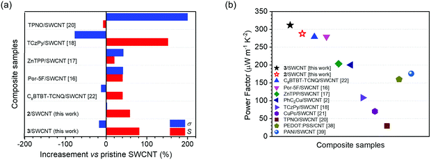
We also plotted the alterations of Seebeck coefficient and electrical conductivity in this work along with literature reports for composites made of OSCs and SWCNTs as shown in Fig. 4a. It is noteworthy that the 2/SWCNT and 3/SWCNT composite films in this work showed a fierce enhancement of their Seebeck coefficient value with a trace of sacrifice in their electrical conductivities, which showed an obvious advantage over other composite films.16–23 Compared with the pristine SWCNTs, the 2/SWCNT and 3/SWCNT composites showed obvious 58% and 81% enhancements of the Seebeck coefficient, respectively, and slight effects on the values electrical conductivity (2% increase for 2/SWCNT and 17% reduction for 3/SWCNT). As a result, the power factors of the 2/SWCNT and 3/SWCNT composites are higher than the reported composites of SWCNTs and OSCs or the composites of SWCNTs and conducting polymers38,39 (Fig. 4b).
2.3 Photophysical properties
To study the interactions between SWCNTs and the OSCs, pristine SWCNTs and the composite films with the OSC loading of 50% are characterized with ultraviolet photoemission spectroscopy (UPS), UV-vis-NIR absorption and Raman spectroscopy. As shown in the UPS spectra (Fig. 5a), the secondary electron cutoffs shift to low bonding energy compared with that of pristine SWCNTs. By subtracting the binding energy of cutoffs from the excitation energy, the work function (WF) of the pristine SWCNTs is then calculated as 4.47 eV. In contrast, the work function of the composite films is found to significantly shift toward higher kinetic energies to 4.51 eV for 1/SWCNT, 4.59 eV for 2/SWCNT, 4.52 eV for 3/SWCNT, 4.52 eV for 4/SWCNT, and 4.49 eV for 5/SWCNT, respectively. The increased WFs of composite films indicate p-type doping that the Fermi levels downward shift towards the HOMO levels resulting in increased carrier concentration. The composite films based on the butterfly-shaped OSCs (1–4) show larger work function compared with the composite film based on planar OSC 5 suggesting that more electron transfer occurred between the SWCNT bundles and the butterfly-shaped molecules. These results indicated that the composite films have different p-doping levels of 2 > 3 ≈ 4 > 1 > 5, which matches well with the electrical conductivities as measured in the TE test.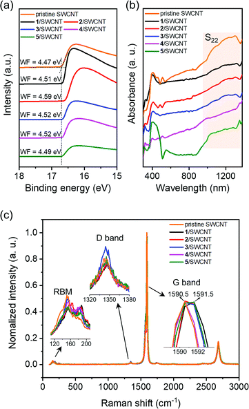 | ||
| Fig. 5 Photophysical characterization of pristine SWCNT and OSCs/SWCNT composite films with OSC loading of 50%: (a) UPS spectra, (b) UV-vis-NIR spectra, and (c) Raman spectra. | ||
UV-vis-NIR absorption spectra of pristine SWCNTs and the composite films are shown in Fig. 5b, exhibiting a clear absorption band of S22, which is attributed to electron transitions between van Hove singularities in semiconducting SWCNTs.40,41 Compared with the pristine SWCNT and the 5/SWCNT composite films, a clear absorption reduction of the S22 peak is observed for the composite films based on butterfly-shaped OSCs, indicating stronger interactions between the SWCNTs and the butterfly-shaped molecules.
Raman spectra of pristine SWCNTs and composite films show the characteristic bands of the graphite-like G band (∼1591 cm−1), D band (∼1345 cm−1), radial breathing mode (RBM, ∼135 cm−1), and G′ band (∼2680 cm−1) (Fig. 5c). RBM is a bond-stretching out-of-plane phonon mode for which all the carbon atoms moved coherently in the radial direction. The RBM intensity reduction of the composite films indicates that the organic small molecules attached on the SWCNT surfaces, which hindered the vibration of the carbon atom in the radial direction. The characteristic Raman bands of the SWCNT-doped composite films involve the G band representing the in-plane stretching vibration of sp2 hybridized carbon atoms, and the D band which is related to defect-induced resonant scattering. All films exhibit a small D peak, and the D/G ratios of the composite films are comparable to that of the pristine SWCNTs, indicating that no distinct structural defects are observed during the film fabrication process. The G band of the composite films (1591.5 cm−1) exhibits an upshift compared with that of the pristine SWCNTs (1590.5 cm−1). These upshifts indicate that electron transfer occurred from the SWCNTs to organic small molecules, suggesting efficient p-type doping.17,22 These results suggest strong charge transfer interactions between organic small molecules and SWCNTs, which is beneficial for establishing continuous conductive networks.
2.4 Thermoelectric generator performance
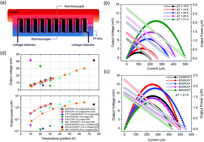
Flexible organic thermoelectric generators (TEGs) composed of 10 active p-type thermoelectric legs are fabricated by drop-casting of composite solutions onto uniform polyimide (PI) substrates (Fig. 6a). The composite films on PI substrates exhibit relatively stable thermoelectrical properties with less than 10% reduction over 400 bending times (Fig. S10 in the ESI†). When a temperature difference (ΔT = Thot − Tcold) is applied to the module, a noticeable voltage difference was created rapidly and the experimentally measured open-circuit voltage linearly increases with ΔT (Fig. S12a in the ESI†). At least three TE modules made by the same composite films are measured and show small variations of the TEG performances (Table S2 in the ESI†). The current–voltage–power characteristics of the TE module based on 2/SWCNT are measured at various temperature gradients as shown in Fig. 6b. The voltage and current increased with increasing the temperature gradients with the highest open-circuit voltage of 16.6 mV and the highest short-circuit current of 498.8 μA. The power–current output and voltage–current output curves for five TE modules are measured at the same temperature gradient of 31 K, showing maximum output power with 1.54 μW for 1/SWCNT, 2.08 μW for 2/SWCNT, 1.89 μW for 3/SWCNT, 1.44 μW for 4/SWCNT and 1.19 μW for 5/SWCNT, respectively (Fig. 6c). The low temperature gradient (ΔT < 35 K) is chosen to obtain accurate temperature measurement, and is suitable for natural environment applications. The TE modules of 2/SWCNT show the maximum output power of 2.08 μW, which is approximately two times larger than that of 5/SWCNT. The TE modules based on butterfly-shaped molecules have better thermoelectric conversion capability than that of 5/SWCNT, which is due to the enhanced power factors resulting from the higher activation energy Ea, improved doping level and charge transport process between the organic compounds and SWCNT. The output powers of 2/SWCNT and 3/SWCNT are also higher than the values of reported p-type42–45 and p–n type46–48 TEGs at different temperature gradients (Fig. 6d), indicating that the butterfly-shaped molecules and SWCNT composites are promising thermoelectric materials.3. Conclusions
In summary, the above study puts forth a new design of organic semiconductor and SWCNT composites for high-performance p-type thermoelectric materials. The key of this design is butterfly-shaped small-molecule organic semiconductors which have finely-tuned frontier molecule orbitals and contorted molecular structures. The introduction of carbonyl and crowded thienyl groups onto the backbones generally contorts the molecular structures leading to the enlarged activation energy Ea that contributes to high Seebeck coefficients of the butterfly-shaped molecules. The contorted structures are also beneficial for enhancing the interactions between butterfly-shaped molecules and the curved surface of SWCNTs, resulting in improved doping level. The composite films of 2/SWCNT show a maximum power factor of 312 μW m−1 K−2 at 350 K, which is approximately 2–3 times larger than that of pristine SWCNTs and the composite film based on planar molecule 5, respectively. Consequently, the corresponding TE module containing 10 p-type legs exhibits a large output voltage of 16.6 mV and output power of 2.08 μW under a 31 K temperature gradient, which is approximately two times higher than the TE module based on 5/SWCNT and sets a new record for p-type thermoelectric composites based on small-molecule OSCs. This work demonstrates that butterfly-shaped organic semiconductor and SWCNT composites are promising thermoelectric materials for future applications in energy conversion and utilization.Conflicts of interest
The authors declare that they have no conflict of interest.Acknowledgements
We gratefully acknowledge financial support from the National Natural Science Foundation of China (Grant No. 51603124 and 51773118), the Natural Science Foundation of Guangdong Province (2019A1515012179), and the Shenzhen Sci & Tech Research Grant (JCYJ20180305124832322 and JCYJ20180305125204446). We thank the Instrumental Analysis Centre of Shenzhen University for analytical support.Notes and references
- Q. Zhang, Y. Sun, W. Xu and D. Zhu, Adv. Mater., 2014, 26, 6829–6851 CrossRef CAS PubMed.
- R. Kroon, D. A. Mengistie, D. Kiefer, D. Kiefer, J. D. Ryan, L. Yu and C. Müller, Chem. Soc. Rev., 2016, 45, 6147–6164 RSC.
- H. Wang and C. Yu, Joule, 2019, 3, 53–80 CrossRef CAS.
- H. Fritzsche, Solid State Commun., 1971, 9, 1813–1815 CrossRef CAS.
- D. Huang, H. Yao, Y. Cui, Y. Zou, F. Zhang, C. Wang, H. Shen, W. Jin, J. Zhu, Y. Diao, W. Xu, C.-A. Di and D. Zhu, J. Am. Chem. Soc., 2017, 139, 13013–13023 CrossRef CAS PubMed.
- K. P. Pernstich, B. Rössner and B. Batlogg, Nat. Mater., 2008, 7, 321–325 CrossRef CAS PubMed.
- H. Yao, Z. Fan, H. Cheng, X. Guan, C. Wang, K. Sun and J. Ouyang, Macromol. Rapid Commun., 2018, 39, 1700727–1700748 CrossRef PubMed.
- K. Yusupov, S. Stumpf, S. You, A. Bogach, P. M. Martinez, A. Zakhidov, U. S. Schubert, V. Khovaylo and A. Vomiero, Adv. Funct. Mater., 2018, 28, 1801246–1801256 CrossRef.
- J. L. Blackburn, A. J. Ferguson, C. Cho and J. C. Grunlan, Adv. Mater., 2018, 30, 1704386–1704420 CrossRef PubMed.
- L. Brownlie and J. Shapter, Carbon, 2018, 126, 257–270 CrossRef CAS.
- L. Wang, C. Pan, Z. Chen, X. Zhou, C. Gao and L. Wang, Polym. Chem., 2018, 9, 4440–4447 RSC.
- C. Gao, Y. Liu, Y. Gao, Y. Zhou, X. Zhou, X. Yin, C. Pan, C. Yang, H. Wang and G. Chen, J. Mater. Chem. A, 2018, 6, 20161–20169 RSC.
- F. Zhang, Y. Zang, D. Huang, C.-A. Di, X. Gao, H. Sirringhaus and D. Zhu, Adv. Funct. Mater., 2015, 25, 3004–3012 CrossRef CAS.
- X. Zhou, C. Pan, C. Gao, A. Shinohara, X. Yin, L. Wang, Y. Li, Q. Jiang, C. Yang and L. Wang, J. Mater. Chem. A, 2019, 7, 10422–10430 RSC.
- J. Lee, A.-R. Han, H. Yu, T. J. Shin, C. Yang and J. H. Oh, J. Am. Chem. Soc., 2013, 135, 9540–9547 CrossRef CAS PubMed.
- Y. Zhou, X. Yin, Y. Liu, X. Zhou, T. Wan, S. Wang, C. Gao and L. Wang, ACS Sustainable Chem. Eng., 2019, 7, 11832–11840 CrossRef CAS.
- Y. Zhou, Y. Liu, X. Zhou, Y. Gao, C. Gao and L. Wang, J. Power Sources, 2019, 423, 152–158 CrossRef CAS.
- X. Yin, Y. Peng, J. Luo, X. Zhou, C. Gao, L. Wang and C. Yang, J. Mater. Chem. A, 2018, 6, 8323–8330 RSC.
- W. Xing, J. Chen, Y. Liang, Y. Zou, Y. Sun, W. Xu and D. Zhu, RSC Adv., 2019, 9, 31840–31845 RSC.
- C. Cao and G. Chen, Small, 2018, 14, 1703453–1703458 CrossRef PubMed.
- Y. Chen, S. Qu, W. Shi, Q. Yao and L. Chen, Carbon, 2020, 159, 471–477 CrossRef CAS.
- J. Tan, Z. Chen, D. Wang, S. Qin, X. Xiao, D. Xie, D. Liu and L. Wang, J. Mater. Chem. A, 2019, 7, 24982–24991 RSC.
- N. Feng, C. Gao, C.-Y. Guo and G. Chen, ACS Appl. Mater. Interfaces, 2018, 10, 5603–5608 CrossRef CAS PubMed.
- L. Wang, J. Dai and Y. Song, New J. Chem., 2019, 43, 12440–12464 RSC.
- M. P. Fernández-Liencres, T. Peña-Ruiz, J. M. Granadino-Roldán, M. Moral, A. Valenzuela-Pereira, A. Garzón-Ruiz and A. Navarro, J. Phys. Chem. C, 2018, 122, 12002–12014 CrossRef.
- R. S. Rao, B. Yadagiri, G. D. Sharma and S. P. Singh, Chem. Commun., 2019, 55, 12535–12538 RSC.
- Q. Xiao, Y. Li, F. Wu, M. Han, M. Xie, Z. Li, L. Zhu and Z. Li, J. Mater. Chem. C, 2018, 6, 10547–10556 RSC.
- C.-Y. Chiu, B. Kim, A. A. Gorodetsky, W. Sattler, S. Wei, A. Sattler, M. Steigerwald and C. Nuckolls, Chem. Sci., 2011, 2, 1480–1486 RSC.
- S. Y. Lee, T. Yasuda, Y. S. Yang, Q. Zhang and C. Adachi, Angew. Chem., Int. Ed., 2014, 53, 6402–6406 CrossRef CAS PubMed.
- X. Shi, S. Liu, C. Liu, Y. Hu, S. Shi, N. Fu, B. Zhao, Z. Wang and W. Huang, Chem. – Asian J., 2016, 11, 2188–2200 CrossRef CAS PubMed.
- H. Zhang, Y. Wang, K. Shao, Y. Liu, S. Chen, W. Qiu, X. Sun, T. Qi, Y. Ma, G. Yu, Z. Su and D. Zhu, Chem. Commun., 2006, 755–757 RSC.
- R. Sekiya, K. Kiyo-oka, T. Imakubo and K. Kobayashi, J. Am. Chem. Soc., 2000, 122, 10282–10288 CrossRef CAS.
- J. Wang, K. Liu, Y.-Y. Liu, C.-L. Song, Z.-F. Shi, J.-B. Peng, H.-L. Zhang and X.-P. Cao, Org. Lett., 2009, 11, 2563–2566 CrossRef CAS PubMed.
- N. J. Hestand and F. C. Spano, Acc. Chem. Res., 2017, 50, 341–350 CrossRef CAS PubMed.
- S. L. Kim, K. Choi, A. Tazebay and C. Yu, ACS Nano, 2014, 8, 2377–2386 CrossRef CAS PubMed.
- K. C. See, J. P. Feser, C. E. Chen, A. Majumdar, J. J. Urban and R. A. Segalman, Nano Lett., 2010, 10, 4664–4667 CrossRef CAS PubMed.
- A. B. Kaiser and V. Skákalová, Chem. Soc. Rev., 2011, 40, 3786–3801 RSC.
- C. Yu, K. Choi, L. Yin and J. C. Grunlan, ACS Nano, 2011, 5, 7885–7892 CrossRef CAS PubMed.
- Q. Yao, Q. Wang, L. Wang and L. Chen, Energy Environ. Sci., 2014, 7, 3801–3807 RSC.
- W. Zhou, Q. Fan, Q. Zhang, L. Cai, K. Li, X. Gu, F. Yang, N. Zhang, Y. Wang, H. Liu, W. Zhou and S. Xie, Nat. Commun., 2017, 8, 14886–14894 CrossRef CAS PubMed.
- D. R. Samarajeewa, G. R. Dieckmann, S. O. Nielsen and I. H. Musselman, Carbon, 2013, 57, 88–98 CrossRef CAS.
- J. Tan, H. Huang, D. Wang, S. Qin, X. Xiao, Z. Chen, D. Liu and L. Wang, J. Mater. Chem. C, 2020, 8, 4827–4835 RSC.
- C. J. An, Y. C. Lee, Y. H. Kang and S. Y. Cho, Carbon, 2017, 124, 662–668 CrossRef CAS.
- C. T. Hong, Y. H. Kang, J. Ryu, S. Y. Cho and K.-S. Jang, J. Mater. Chem. A, 2015, 3, 21428–21433 RSC.
- R. Niu, C. Pan, Z. Chen, L. Wang and L. Wang, Chem. Eng. J., 2020, 381, 122650–122657 CrossRef CAS.
- G. Wu, Z.-G. Zhang, Y. Li, C. Gao, X. Wang and G. Chen, ACS Nano, 2017, 11, 5746–5752 CrossRef CAS PubMed.
- Y. Liu, Q. Dai, Y. Zhou, B. Li, X. Mao, C. Gao, Y. Gao, C. Pan, Q. Jiang, Y. Wu, Y. Xie and L. Wang, ACS Appl. Mater. Interfaces, 2019, 11, 29320–29329 CrossRef CAS PubMed.
- Y. Wang, Z. Chen, H. Huang, D. Wang, D. Liu and L. Wang, J. Mater. Chem. A, 2020, 8, 24675–24684 RSC.
Footnote |
| † Electronic supplementary information (ESI) available. CCDC 2039214 and 2039215. For ESI and crystallographic data in CIF or other electronic format see DOI: 10.1039/d0mh01679a |
| This journal is © The Royal Society of Chemistry 2021 |

