Recent advances in MOF-based photocatalysis: environmental remediation under visible light
Qi
Wang
*ab,
Qiaoyuan
Gao
a,
Abdullah M.
Al-Enizi
c,
Ayman
Nafady
c and
Shengqian
Ma
 *b
*b
aSchool of Environmental Science and Engineering, Zhejiang Gongshang University, Hangzhou 310018, China
bDepartment of Chemistry, University of South Florida, Tampa, FL 33620, USA. E-mail: wangqi8327@zjgsu.edu.cn; sqma@usf.edu
cChemistry Department, College of Science, King Saud University, Riyadh, 11451, Saudi Arabia
First published on 30th October 2019
Abstract
Visible light-induced photocatalysis is a promising way for environmental remediation due to efficient utilization of solar energy. Recently, metal–organic frameworks (MOFs) have attracted increasing attention in the field of photocatalysis. In comparison with traditional metal oxide semiconductors, MOFs have many advantages, such as high specific surface area, rich topology and easily tunable porous structure. In this review, we aim to summarize and illustrate recent advances in MOF-based photocatalysis for environmental remediation under visible light, including wastewater treatment, air purification and disinfection. A series of strategies have been designed to modify and regulate pristine MOFs for enhanced photocatalytic performance, such as ligand functionalization, mixed-metal/linker strategy, metal ion/ligand immobilization, dye sensitization, metal nanoparticle loading, carbon material decoration, semiconductor coupling, MOF/COF coupling, carrier loading and magnetic recycling. The above modifications may result in extended visible light absorption, efficient generation, separation and transfer of photogenerated charges, as well as good recyclability. However, there are still many challenges and obstacles. In order to meet the requirements of using MOF photocatalysis as a friendly and stable technology for low-cost practical applications, its future development prospects are also discussed.
1. Introduction
In the 21st century, environmental pollution and fossil energy crisis have become two major problems that plague human survival and development. Among various renewable energy sources, solar energy is a kind of abundant and clean choice. Thus, solar light-driven technologies for environmental remediation have attracted great attention. Herein, heterogeneous photocatalysis, as represented by TiO2, was proved to be a feasible way. Upon UV light irradiation, electron–hole (e−–h+) pairs can be generated in TiO2, leading to reductive and oxidative reactions.1 In this way, various kinds of refractory organic pollutants can be degraded and heavy metal ions can be reduced by TiO2 photocatalysis.2 However, UV light accounts for less than 5% of incident solar light, so the utilization of visible light (nearly 45%) is more promising for better utilization of solar energy and future large-scale practical applications. Consequently, there is an urgent need to develop more visible light-responsive photocatalysts with high activity and stability.Metal–organic frameworks (MOFs) are a class of porous crystalline materials consisting of metallic nodes (metal ions or clusters) and organic linkers.3 Due to their ultra-high specific surface area (over 6000 m2 g−1),4 rich topology and easily tunable porous structure,5 MOFs have recently attracted increasing attention in the field of photocatalysis.6–10 Distinct from classical inorganic semiconductors with a delocalized conduction band (CB) and valence band (VB), MOFs can be identified as molecules arranged in a crystalline lattice. In addition, some MOFs, such as MOF-5 (Zn4O(BDC)3, BDC: 1,4-benzenedicarboxylate), UiO-66 (Zr6O4(OH)4(BDC)6, UiO: University of Oslo) and MIL-125 (Ti8O8(OH)4(BDC)6, MIL: Materials Institute Lavoisier) displayed semiconductor-like behavior. Herein, the metal-oxo clusters and organic linkers can be regarded as isolated semiconductor quantum dots and light-absorbing antenna, respectively.11–13 In the past few decades, with the development of water/acid-resistant MOF materials,14 more and more light-responsive MOFs have been reported for the photocatalytic removal of pollutants,2,8 disinfection of bacteria,15 production of H2,16,17 fixation of CO2,18 selective transformation of organics19etc.20,21
Since there are a large number of selections between metal ions/clusters and organic linkers, MOFs are endowed as extremely tunable photocatalysts for efficient utilization of solar light. In the past five years, there are many reviews discussing various aspects of MOFs,6–9,16,22–26 including environmental applications. For example, Wang et al. summarized the photocatalytic degradation of organic pollutants from wastewater in 2014.27 At that moment, most photoactive MOFs were applied for the degradation of dyes under UV or UV-Vis light irradiation. Very small numbers of MOFs utilizing visible light were listed and usually need the assistance of H2O2 as an oxidant. Later in 2016, Wang et al. further conducted a mini-review on the photocatalytic reduction of Cr(VI) by MOFs.8 In the same year, Ye's group also summarized the progress in MOF photocatalysis. They mainly focused on several representative MOFs, including MOF-5, UiO-66(Zr), MIL-125(Ti) and MIL-101(Fe). In comparison with traditional semiconductors, the reported MOFs or MOF-based composites displayed promising photocatalytic performance, especially in CO2 reduction.28 The modified MOFs as photocatalysts were also reviewed by Qiu et al.29 They focused on the progress of various modification strategies to typical light-responsive MOFs. Enhanced photocatalytic performance (pollutant removal, CO2 reduction, H2 production or organic transformation) was reported utilizing UV, UV-Vis or visible light. Meanwhile, Bedia et al. conducted a review on the synthesis and characterization of MOFs for photocatalytic water purification.30 Besides, a short review concerning iron-based MOFs for visible light-induced photocatalysis was also reported.31 In this year, Jiang's group summarized their recent contributions toward MOF-based photocatalysis and photothermal catalysis, mainly focusing on H2 production and selective organic transformations.24 However, there were limited reviews focusing on visible light-responsive MOFs, especially for environmental remediation. With the increasing variety of MOFs and MOF-based composites, invaluable application prospects will be expected.
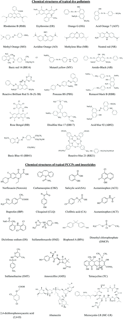
Thus, based on the above analysis, this review aims at recent advances in MOF-based photocatalysis for environmental remediation under visible light, including wastewater treatment, air purification and disinfection. For example, various kinds of organic dyes, phenolic compounds, insecticides, pharmaceuticals and personal care products (PPCPs) in aqueous media can be photodegraded. The structures of typical organic pollutants photodegraded by MOFs are presented in Fig. 1. Besides, the highly migratable Cr(VI) and radiative U(VI) can be photoreduced to their corresponding trivalent states,8,32 which can be easily precipitated and separated from aqueous solution. Gaseous pollutants such as NO and toluene can be photo-oxidized into harmless products.33 Inactivation of bacterial was also reported.34 Thus, for better understanding and easy reading, this review begins with pristine MOFs that can work under visible light. Strategies for engineering MOFs for enhanced performance are further presented, including ligand functionalization, mixed-metal/linker strategy, metal ion/ligand immobilization, dye sensitization, metal nanoparticle loading, carbon material decoration, semiconductor coupling, MOF/COF coupling, carrier loading and magnetic recycling.
2. The development of photoactive MOFs from UV to visible light
Early in 1999, MOF-5 was synthesized by Yaghi's group.35 In 2004, the optical and vibrational properties of MOF-5 were investigated by Zecchina's group using UV-Vis Diffuse Reflectance Spectroscopy (UV-Vis DRS), photoluminescence (PL) spectroscopy and Raman spectroscopy. It was proposed that Zn4O13 clusters and organic ligands in MOF-5 can behave as ZnO quantum dots (QDs) and light-absorbing antenna, respectively.36 Until 2007, the semiconductor behavior of MOF-5 was demonstrated by Garcia's group via later laser flash photolysis, and the application of MOF-5 as a photocatalyst for phenol degradation was first tested.37 The charge-transfer processes on MOF-5 were further studied via photoluminescence.38 Despite these, MOF-5 decomposed gradually upon exposure to moisture in air or in water.35 The instability of MOF-5 motivated researchers to find or synthesize more stable photocatalytic MOFs.According to metal–ligand bond strengths and the HSAB (hard/soft acid/base) principle,5 stable MOFs can be synthesized using either a hard or soft Lewis base. As shown in Fig. 2, high-valent metal ions (such as Ti4+, Zr4+, Al3+, Fe3+ and Cr3+) with a hard Lewis base (carboxylates) can lead to the formation of stable MOFs. The MIL series (MIL: Material Institute Lavoisier) and UiO-66(Zr) (UiO: University of Oslo) are representative MOFs with good stability. Besides, divalent metal ions (such as Zn2+, Co2+, Cu2+ and Ni2+) with a soft Lewis base (azolates) resulted in several stable MOFs. Among which, zeolitic imidazolate frameworks (ZIFs) constructed by Zn2+ and imidazolate linkers were the most representative examples. Consistent with the above classifications, water-stable UiO-66(Zr) was fabricated and displayed photocatalytic activity for H2 evolution.40,41 Besides, MIL-125(Ti) was highly photosensitive and water-stable, which can be photoexcited by UV light leading to the reduction of the Ti(VI) center and oxidation of adsorbed alcohol molecules.42
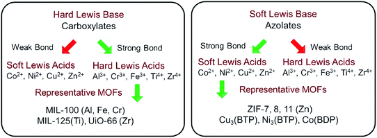 | ||
| Fig. 2 Strategies to construct stable MOFs guided by HSAB theory. Adapted with permission from ref. 39, © 2018 WILEY-VCH. | ||
Based on the principle of traditional semiconductor photocatalysis, a photocatalyst can be directly excited by incident light with energy (Elight) larger than the band gap (Eg). In this way, electron–hole (e−–h+) pairs can be generated (Fig. 3). Similarly, electron transitions can also occur from the highest occupied molecular orbital (HOMO) to the lowest unoccupied molecular orbital (LUMO) in MOFs, leaving holes (h+) in the HOMO. Herein, the HOMO/LUMO plays similar roles as the CB/VB in semiconductors. Namely, the photogenerated electrons in the LUMO can be transferred to O2, leading to the formation of superoxide radicals (O2˙−). Meanwhile, holes in the HOMO can oxidize the surface hydroxyl group/water, generating hydroxyl radicals (HO˙). Due to the presence of reactive species (O2˙−, HO˙ and h+), organic pollutants can be degraded. However, the band gaps (EHOMO–LUMO) were reported to be ca. 3.4 eV, 3.9 eV and 3.6 eV for MOF-5, UiO-66(Zr) and MIL-125(Ti), respectively.37,43–45 For effective excitation of such MOFs, the incident light (Elight = 1240/λ > EHOMO–LUMO) was restricted to UV light with a short wavelength (λ < 365 nm). Thus, for efficient utilization of solar energy, MOFs responsive to visible light (λ > 400 nm, or Elight < 3.1 eV) are more desirable.
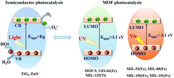 | ||
| Fig. 3 Mechanism for semiconductor photocatalysis (left); comparison of band gaps and light source (UV or visible light) between representative MOFs (right). | ||
In contrast to MOFs with wide bandgaps, Fe-MOFs are extremely appealing. The extensive Fe–O clusters can be directly excited by visible light, leading to more efficient utilization of solar energy. Besides, the application cost of Fe-MOFs will be much cheaper due to the Earth-abundant nature of the Fe element. As shown in Fig. 4A, using Fe(NO3)3 or FeCl3 as the Fe3+ precursor, and terephthalic acid (H2BDC), fumaric acid (H2FUM) or benzene-1,3,5-tricarboxylic acid (H3BTC) as the ligand precursor, various kinds of Fe-MOFs (MIL-53, MIL-68, MIL-88A, MIL-88B, MIL-100 and MIL-101) can be obtained. As summarized in Table 1,39,46 the corresponding EHOMO–LUMO values ranged from 1.88 eV to 2.88 eV, which can be directly excited by visible light. Various kinds of organic pollutants (RhB, MB, AO7, CA, CBZ etc.) were reported to be degraded by Fe-MOFs under visible light. However, under most circumstances, H2O2 was added as an electron acceptor to accelerate the degradation process. Besides, photocatalytic reduction of Cr(VI) or U(VI) can also be achieved on MIL-53(Fe) using (NH4)2C2O4 or HCOOH as the h+ scavenger.32,47
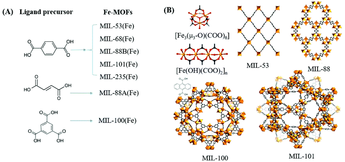 | ||
| Fig. 4 (A) Fe-MOFs prepared with different ligand precursors; (B) structures of metal clusters and representative MIL series of Fe-MOFs. Adapted with permission from ref. 39, © 2018 WILEY-VCH. | ||
| MOF | Clusters | Ligands | E HOMO–LUMO (eV) |
S
BET![[thin space (1/6-em)]](https://www.rsc.org/images/entities/char_2009.gif) a (m2 g−1) a (m2 g−1) |
Pollutant | C pollutant (mg L−1) | C catalyst (g L−1) | Time (min) | η (%) | Ref. |
|---|---|---|---|---|---|---|---|---|---|---|
| a S BET surface area is presented in integer numbers. b UV-Vis light or sunlight. c Removal efficiencies (η) for pollutants are used as received or estimated from the figures in the reference and presented in integer numbers. NA: no experimental data available; PS: persulfate; PMS: peroxymonosulfate; SPC: percarbonate; SMT: sulfamethazine; H2BDC: terephthalic acid; H2FUM: fumaric acid; H3BTC: benzene-1,3,5-tricarboxylic acid; H2ANDC: anthracene-9,10-dicarboxylic acid; H2NDC: 2,6-naphthalenedicarboxylic acid; H2CPEB: 1,4-bis(2-[4-carboxyphenyl]ethynyl) benzene; H2mna: 2-mercaptonicotinic acid; H2TCPP: tetrakis (4-carboxyphenyl) porphyrin. | ||||||||||
| MIL-53(Fe) | [Fe(OH)(COO)2]n | H2BDC | 2.62 | NA | AO7 (with PS) | 17.5 | 0.6 | 90 | 100 | 58 |
| 2.88 | 19 | RhB (with H2O2) | 10 | 0.4 | 50 | 98 | 59 | |||
| 2.69 | 38 | RhB (with H2O2) | 10 | 0.4 | 180 | 90 | 60 | |||
| 2.55 | 16 | RhB (with PMS) | 40 | 1.0 | 20 | 95 | 61 | |||
| 2.72 | NA | MB | 128 | 0.01 | 60 | 20b | 62 | |||
| NA | 184 | CA (with H2O2) | 40 | 0.1 | 280 | 98 | 63 | |||
| CBZ (with H2O2) | 40 | 0.1 | 280 | 90 | ||||||
| 2.72 | NA | Cr(VI) (with (NH4)2C2O4) | 20 | 1.0 | 40 | 100 | 47 | |||
| 2.72 | NA | U(VI) (with HCOOH, N2) | 50 | 0.4 | 120 | 80 | 32 | |||
| 2.91 | NA | SMT (with Fe(III), SPC) | 5.6 | 0.2 | 60 | 91 | 64 | |||
| MIL-68(Fe) | [Fe(OH)(COO)2]n | H2BDC | 2.80 | NA | Cr(VI)(with (NH4)2C2O4) | 20 | 0.25 | 5 | 100 | 65 |
| Cr(VI) (with MG) | 10 | 0.25 | 240 | 95 | ||||||
| MG (with Cr(VI)) | 30 | 0.25 | 240 | 80 | ||||||
| MIL-88B(Fe) | [Fe3(μ3-O)(COO)6] | H2BDC | NA | NA | MB | 10 | 0.25 | 50 | 100 | 66 |
| RhB | 10 | 0.25 | 60 | 94 | ||||||
| MIL-101(Fe) | [Fe3(μ3-O)(COO)6] | H2BDC | 1.88 | 252 | TC | 50 | 0.5 | 180 | 97 | 54 |
| MOF-235(Fe) | [Fe3(μ3-O)(COO)6] | H2BDC | 1.94 | 148 | RhB (with H2O2) | 19.2 | 0.2 | 20 | 100 | 67 |
| MIL-88A(Fe) | [Fe3(μ3-O)(COO)6] | H2FUM | 2.05 | NA | MB (with H2O2) | 32 | 0.4 | 20 | 100 | 68 |
| MIL-100(Fe) | [Fe3(μ3-O)(COO)6] | H3BTC | NA | 1974 | MO | 5 | 0.33 | 420 | 40b | 69 |
| HKUST-1 | [Cu2(CO2)4] | H3BTC | 2.63 | 197 | MG | 10 | 0.25 | 85 | 98 | 70 |
| SO | 15 | 0.25 | 85 | 89 | ||||||
| MIL-53(Al) | [Al(OH)(COO)2]n | H2BDC | 3.87 | NA | MB | 128 | 0.1 | 60 | 30b | 62 |
| MIL-53(Cr) | [Cr(OH)(COO)2]n | H2BDC | 3.20 | NA | MB | 128 | 0.01 | 60 | 32b | 62 |
| UiO-66(AN) | [Zr6(μ3-O)4(μ3-OH)4(COO)12] | H2ANDC | 2.47 | 627 | MO | 20 | 0.1 | 90 | 65 | 56 |
| UTSA-38 | [(Zn4O)(COO)6] | H2NDC | 2.85 | 1690 | MO | 20 | 0.4 | 120 | 64b | 71 |
| VNU-1 | [Zr6O4(OH)4(CO2)12] | H2CPEB | 2.88 | 2100 | MB | 100 | 0.67 | 180 | 100b | 57 |
| MO | 100 | 0.67 | 180 | 83b | ||||||
| Bi-mna | NA | H2mna | NA | 35 | RhB | 20 | 1.0 | 120 | 96 | 72 |
| MB | 20 | 1.0 | 120 | 95 | ||||||
| PCN-222 | [Zr6(μ3-O)4(μ3-OH)4(OH)4(H2O)4(COO)8] | H2TCPP | NA | 1914 | BPA | 100 | 1.0 | 120 | 90 | 73 |
Among the various visible light-responsive Fe-MOFs mentioned above, MIL-100(Fe) with a tricarboxylate linker was theoretically more stable than Fe-MOFs (MIL-53, MIL-88 and MIL-101) with a dicarboxylate linker.5 As illustrated in Fig. 4B, both MIL-100(Fe) and MIL-101(Fe) display 3D structures. Among which, MIL-100(Fe) possesses thermal and water stability.48 Whereas, MIL-101(Fe) may be transformed into MIL-53 or MIL-88 in strong polar solvents.49,50 Furthermore, MIL-100 was reported to have higher water stability than UiO and ZIF.51–53 The non-toxicity of MIL-100 was also verified by in vivo toxicity assays. Thus, MIL-100(Fe) is expected to be a promising visible light-responsive photocatalyst for environmental remediation. Using antibiotic tetracycline (TC) as the target pollutant, the performance of MIL-53(Fe), MIL-100(Fe) and MIL-101(Fe) was compared by Wang et al.54 However, MIL-101(Fe) rather than MIL-100(Fe) exhibited the highest performance (Fig. 5A). TC can be removed via both adsorption and photocatalysis with a value of ca. 97% by MIL-101(Fe) after 180 min visible light irradiation. The rate constant (k) was calculated to be 1.6 × 10⁻² min−1 (Fig. 5B), which was 7.1 and 1.8 times that in MIL-53(Fe) and MIL-100(Fe), respectively. However, the highest specific surface area (SBET) was observed in MIL-100(Fe) (1203 m2 g−1), which was much larger than that of MIL-101(Fe) (253 m2 g−1) and MIL-53(Fe) (21 m2 g−1). Generally, the catalyst surface played an important role in heterogeneous photocatalysis, and larger SBET was usually beneficial for photocatalysis under other identical conditions. As for MIL-101(Fe), in addition to its highest adsorption of TC, its lowest band gap (1.88 eV) may also be beneficial for the greatest TC removal performance. Thus, the difference in the photocatalytic performance of the tested Fe-MOFs may be influenced by both band gap and adsorption properties. Under different conditions (temperature, solvent, etc.), the different types of Fe-MOFs may have their own advantages and application fields. Further research work should be undertaken to enhance the photocatalytic performance as well as the water/thermo-stability under harsh conditions.
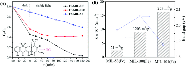 | ||
| Fig. 5 (A) Photocatalytic degradation of TC by different types of Fe-MILs; (B) rate constant for TC removal on different Fe-MILs in comparison with band gaps and specific surface areas. Adapted with permission from ref. 54, © 2018 Elsevier. | ||
In addition to Fe-MOFs, the dicarboxylate and tricarboxylate linkers can interact with other metal ions (such as Cu2+, Al3+ or Cr3+), leading to the formation of visible light-active HKUST-1 (HKUST: Hong Kong University of Science and Technology), MIL-53(Al) or MIL-53(Cr), respectively. With the development of MOF materials, the selection of ligands was extended from the original H2BDC/H3BTC to structures with higher π-conjugation. A large number of visible light-responsive MOFs were synthesized and applied for environmental remediation. For example, the band gap of MOF-5 (4.0 eV) can be reduced to 3.3 eV when using biphenyl or naphthalenedicarboxylic acids as the ligand precursor (Fig. 6A). A novel Zn2+-centered MOF (UTSA-38) with a narrow band gap (2.85 eV) was fabricated using 2,6-naphthalenedicarboxylic acid (H2NDC) as the ligand precursor (Fig. 6B).55 Photocatalytic degradation of methyl orange (MO, 20 mg L−1) was achieved by UTSA-38, despite low efficiency (<30%) under visible light irradiation for 120 min.
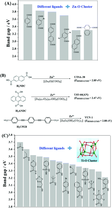 | ||
| Fig. 6 (A) Bandgap engineering of Zn–O clusters with different organic ligands;44 (B) visible light-responsive Zn-MOFs and Zr-MOFs prepared with different ligand precursors; (C) bandgap engineering of Ti–O clusters with different organic ligands.45 Adapted with permission from ref. 44 and 45, © 2008 Wiley-VCH, © 2016 Wiley-VCH. | ||
Moreover, strategies were also developed to utilize the water-stable Ti- and Zr-centered MOFs. Motivated by the findings of MOF-5, the band gaps along with the photocatalytic performance may be tuned by changing the organic linker.44 As for Zr-MOFs, once H2BDC was replaced by anthracene-9,10-dicarboxylic acid (H2ANDC) or 1,4-bis(2-[4-carboxyphenyl]ethynyl) benzene (H2CPEB), UiO-66(AN) or VUN-1 (VNU: Vietnam National University) with a band gap of 2.47 eV and 2.88 eV was obtained (Fig. 6B), respectively.56,57 For the degradation of MO (20 mg L−1), shorter time (90 min) and smaller catalyst dosage (0.1 g L−1) led to 65% removal efficiency under visible light.56 Methylene blue (MB) can be 100% removed by VUN-1 after 180 min UV-Vis irradiation.40 As for Ti-MOFs, the same strategy still works well. The band gap can be engineered when Ti–O clusters were connected with different organic ligands (Fig. 6C).45 The performance of different Ti-MOFs was investigated and compared via photocatalytic water splitting under UV-Vis light.
3. Strategies for engineering visible light-active MOFs
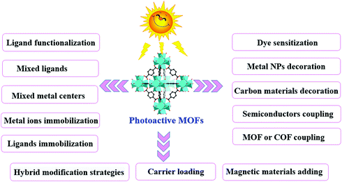
In comparison with traditional metal oxide semiconductors, MOFs have many advantages in photocatalysis because of their inherent structural features (such as large surface area and porous structure) and a tunable combination between metallic nodes and organic linkers. However, the photocatalytic efficiency still cannot meet the actual needs. Many attempts have been made to enhance the photocatalytic performance. As shown in Fig. 7, a series of strategies have been developed for extended visible light absorption, more efficient generation, separation and transfer of charge carriers, as well as good recyclability.3.1 Ligand functionalization
Considering the huge difference in available quantities of metal ions and organic linkers, modification of organic linkers rather than metallic modes will be a powerful strategy to tune the optical properties of MOFs. Taking the most frequently studied H2BDC precursor as an example, MIL-125(Ti) synthesized with unmodified H2BDC can only respond to UV light.42 As shown in Fig. 8, after introducing an –NH2 group into H2BDC, isostructural NH2-MIL-125(Ti) was synthesized in the same way, which displayed yellow color and extended visible light absorption.74 The band gap dramatically decreased from 3.60 eV to 2.46 eV. Besides, due to enhanced CO2 adsorption by the –NH2 group, NH2-MIL-125(Ti) was reported for the first time as a targeted photocatalyst toward CO2 reduction under visible light. Furthermore, dye-like moieties with higher π-conjugated groups were used as substituents to H2BDC.75 The resulting MR-MIL-125(Ti) displayed a clear red shift of optical absorption. The absorption edge reached almost 700 nm, indicating that the band gap was ca. 1.93 eV. Subsequently, a p-type Ti-containing MOF (NTU-9) was also developed, using two –OH group-substituted H2BDC (2,5-dihydroxyterephthalic acid) as an organic linker.76 The light absorption region can be extended up to 750 nm. The red NTU-9 sample can act as a visible light-responsive photocatalyst for dye degradation with the assistance of H2O2. RhB (48 mg L−1) and MB (32 mg L−1) dyes can be completely degraded after 80 min and 20 min visible light irradiation, respectively. Moreover, high stability can also be observed after three cyclic runs.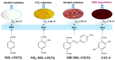 | ||
| Fig. 8 The development history of Ti-MOFs via ligand functionalization and their first application in photocatalysis. | ||
To elucidate the specific role of –NH2 substitution in engineering the optical response of MIL-125(Ti), Hendon et al. carried out detailed research via both experimental and theoretical ways.77 Results indicated that the enhanced optical properties were ascribed to the regulation of the HOMO. The introduction of a single –NH2 group leads to an elevation of 1.2 eV of the HOMO with no influence on the LUMO. The effect of other functional groups (–OH, –CH3, –Cl) as well as diaminated linker BDC-(NH2)2 were also studied. The band gaps decreased in the order of –CH3/–Cl < –OH < –(NH2)2 substitution. Herein, –(NH2)2 substitution was considered as the most powerful method. Besides, the band gap of MIL-125(Ti) can be rationally regulated by changing the ratio between –NH2 and –(NH2)2.77 This strategy can be further extended to other aromatic linkers.
Similar band gap engineering by ligand functionalization was also reported for UiO-66(Zr) and UiO-66(Ce).78,79 For example, Hendrickx et al. conducted a combined theoretical and experimental study on the intrinsic optical properties of UiO-66(Zr).78 As shown in Fig. 9, using mono or bifunctionalized BDC linkers, the band gap of UiO-66(Zr) can be engineered from 4.0 eV to 2.2 eV. The values obtained via HSE06 calculations agreed well with the experimental results. As for the mechanism of band gap engineering, similar to NH2-MIL-125(Ti),77 the decreased band gap was ascribed to the elevation of the HOMO after ligand functionalization.80 Typically, according to the theory of conventional semiconductor photocatalysis, a narrower band gap means more efficient response to visible light, which may have a positive effect on the photocatalytic performance under visible light. Unexpectedly, some difference was reported for MOF photocatalysis. For example, UiO-66–X (X = H, NH2, NO2 or Br) were synthesized and compared for the oxidation of As(III) and the reduction of Cr(VI) under visible light.43 As listed in Table 2, the photocatalytic performance of the as-prepared UiO-66 MOFs was strongly affected by different functionalized linkers. Among the four tested samples, –NH2 functionalization displayed the highest photocatalytic activity for either As(III) oxidation or Cr(VI) reduction. For example, As(III) can be 100% removed by UiO-66–X (X = NH2), while the value was 60%, 18% or 50% for –H, –NO2 or –Br functionalized UiO-66, respectively.43 In comparison with unmodified UiO-66, the absorption edges were red-shifted to ca. 360, 400 and 450 nm for UiO-66–X (X = Br, NO2 and NH2), respectively. Correspondingly, decreased band gaps were estimated from 3.88 to 2.76 eV.
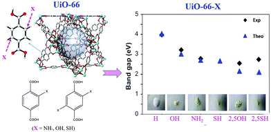 | ||
| Fig. 9 The effect of functionalized BDC linkers on regulating the band gaps of UiO-66(Zr). Adapted with permission from ref. 78, © 2015 American Chemical Society. | ||
| MOFs |
E
HOMO–LUMO![[thin space (1/6-em)]](https://www.rsc.org/images/entities/char_2009.gif) a (eV) a (eV) |
S
BET![[thin space (1/6-em)]](https://www.rsc.org/images/entities/char_2009.gif) b (m2 g−1) b (m2 g−1) |
Pollutant | C pollutant (mg L−1) | C catalyst (g L−1) | Time (min) | η (%) | Ref. |
|---|---|---|---|---|---|---|---|---|
| NA: no experimental data available.a EHOMO–LUMO is used as received or estimated from the adsorption edges of MOFs.b SBET surface area is presented in integer numbers.c Removal efficiencies (η) for pollutants are used as received or estimated from the figures in the reference and presented in integer numbers.d UV-Vis light or sunlight.e Addition of ammonium oxalate under a N2 atmosphere.f Addition of ethanol.g Addition of ethanol under a N2 atmosphere.h Addition of H2O2.i (OH)2-H2BDC as the organic ligand. | ||||||||
| UiO-66(Zr)–X: X substituted H 2 BDC as the ligand precursor | ||||||||
| X = H | 3.88 | 1141 | As(III)d | 2 | 1.0 | 60 | 64 | 43 |
| X = NH2 | 2.76 | 733 | 2 | 1.0 | 60 | 100 | ||
| X = NO2 | 3.10 | 465 | 2 | 1.0 | 60 | 18 | ||
| X = Br | 3.44 | 456 | 2 | 1.0 | 60 | 50 | ||
| X = H | 3.88 | 1141 | Cr(VI)d | 10 | 0.5 | 100 | 20 | 43 |
| X = NH2 | 2.76 | 733 | 10 | 0.5 | 100 | 100 | ||
| X = NO2 | 3.10 | 465 | 10 | 0.5 | 100 | 11 | ||
| X = Br | 3.44 | 456 | 10 | 0.5 | 100 | 15 | ||
| MIL-68(In)–X: X substituted H 2 BDC as the ligand precursor | ||||||||
| X = H | 3.94 | 611 | Cr(VI)d,e | 20 | 1.0 | 60 | 16 | 81 |
| X = NH2 | 2.79 | 584 | 20 | 1.0 | 60 | 100 | ||
| X = NO2 | 3.02 | 582 | 20 | 1.0 | 60 | <5 | ||
| X = Br | 3.70 | 601 | 20 | 1.0 | 60 | 8 | ||
| NH 2 –MOFs: NH 2 functionalization with different metal centers | ||||||||
| MIL-125(Ti) | NA | NA | Cr(VI) | 8 | 0.5 | 45 | 60 | 82 |
| MIL-53(Fe) | NA | NA | 8 | 0.5 | 45 | 17 | ||
| MIL-88B(Fe) | NA | NA | 8 | 0.5 | 45 | 100 | ||
| UiO-66(Zr) | NA | NA | 8 | 0.5 | 45 | 46 | ||
| Development of NH 2 functionalization | ||||||||
| NH2-MIL-101(Fe) | 1.32 | NA | Toluene | 27.6 | 0.16 | 360 | 79 | 33 |
| NH2-UiO-66(Zr) film | 2.90 | NA | Cr(VI) | 5 | 0.5 | 120 | 98 | 83 |
| NH2-UiO-66(Hf) film | 2.88 | NA | Cr(VI) | 5 | 0.9 | 120 | 99 | 83 |
| Hierarchical NH2-MIL-125(Ti) | 2.53 | 1133 | RhB | 100 | 0.4 | 120 | 84 | 84 |
| NH2-MIL-125(Ti) | 2.64 | 1129 | NO | NA | 0.4 | 5 | 31 | 85 |
| NH2-MIL-125(Ti) | 2.75 | 1344 | Cr(VI)f | 48 | 0.4 | 60 | 91 | 86 |
| MIL-68(In)-NH2 | 2.82 | 674 | Cr(VI)g | 20 | 1.0 | 180 | 97 | 87 |
| Other group functionalization | ||||||||
| NTU-9i | 1.72 | NA | RhBh | 48 | 0.5 | 80 | 100 | 76 |
| MBh | 32 | 0.5 | 20 | 100 | ||||
However, the photocatalytic performance for both As(III) oxidation and Cr(VI) reduction was not correlated with band gaps. Only –NH2 functionalization enhanced the photocatalytic performance, while –NO2 and –Br had an inhibitory effect. Based on further exclusion of the influence of specific surface area, the above phenomena can be explained by the electronic effects of ligands. As shown in Fig. 10, the log(KX/KH) correlated well with the Hammett's σm values of different X ligands. Herein, KX and KH represent the rate constants for As(III) oxidation by UiO-66–X and UiO-66 respectively. The electron-donating group (–NH2) with a negative σm value can enhance the electron density around the Zr–O cluster, leading to increased separation and transfer of photogenerated charge carriers. Whereas, the electron-withdrawing groups (–NO2 and –Br) had an opposite effect. Thus, rather than the surface area or band gap, the electronic effect was considered to play a dominating role in affecting the photocatalytic performance of UiO-66–X. Subsequently, the electronic effects of ligand substitution were also demonstrated using functionalized MIL-68(In) for the photocatalytic treatment of Cr(VI)-containing wastewater.81
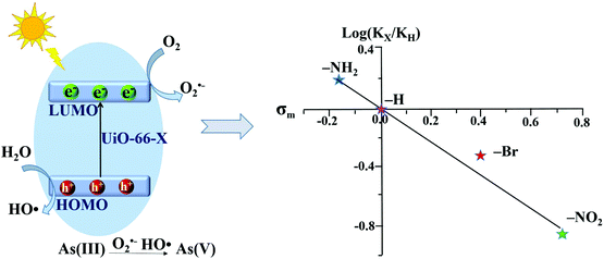 | ||
| Fig. 10 Proposed mechanism (left) and Hammett plot (right) for photocatalytic oxidation of As(III) by UiO-66–X (X = H, NH2, NO2 or Br). Reproduced from ref. 43 with permission from the PCCP Owner Societies. | ||
In addition to UV-active MIL-125(Ti) and UiO-66(Zr), –NH2 functionalization was also applied to Fe-containing MOFs. Similarly, enhanced visible light absorption and photocatalytic performance can be observed. Moreover, the effect of –NH2 functionalization on different MOFs was further investigated.82 For example, the performances of NH2–MIL-88B(Fe), NH2–MIL-125(Ti) and NH2–UiO-66(Zr) were compared for the reduction of aqueous Cr(VI). Among which, NH2–MIL-88B(Fe) displayed the highest activity. Cr(VI) can be totally reduced by NH2–MIL-88B(Fe) within 45 min visible light irradiation (Table 2). Whereas, the values were 60% and 46% by NH2–MIL-125(Ti) and NH2–UiO-66(Zr), respectively. The superior performance of NH2–MIL-88B(Fe) can be explained by dual excitation pathways. Namely, both Fe–O clusters and the –NH2 group can be excited. The electron transfer from the excited –NH2 to the Fe-O center led to increased separation of photogenerated charge carriers, as well as enhanced Cr(VI) reduction.
Moreover, –NH2 functionalized Fe-MOFs also displayed potential application in air purification. For example, Zhang et al. demonstrated that hexagonal NH2-MIL-101(Fe) spindles can be applied for the visible light-induced degradation of gaseous toluene.33 As shown in Fig. 11A, NH2-functionalization dramatically enhanced the visible light absorption of MIL-101(Fe), corresponding to a decreased band gap (1.32 eV). After 6 h visible light irradiation, ca. 79% toluene can be degraded by NH2-MIL-101(Fe). Whereas, the value was ca. 11% by TiO2 (Fig. 11B). The mechanism for toluene degradation was revealed using an in situ FTIR technique (Fig. 11C). Characteristic peaks corresponding to the aromatic ring (3079 and 3038 cm−1) and methyl groups (2937 and 2881 cm−1) in toluene gradually decreased with prolonged irradiation time. Meanwhile, the peaks of CO2 (2362 and 2337 cm−1) gradually increased. The formation of a degradation intermediate (benzoic acid) was also deduced via the signals of the carboxylate group (1504, 1545 and 1562 cm−1). Thus, the oxidative degradation of toluene to CO2 can be confirmed (Fig. 11D).
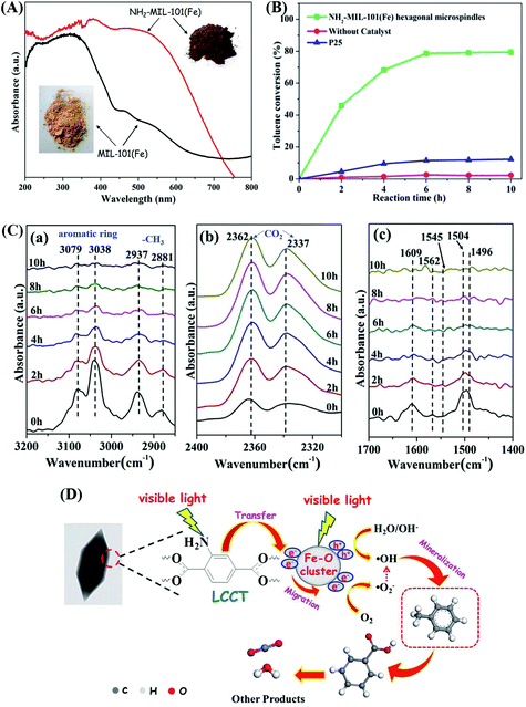 | ||
| Fig. 11 (A) UV-Vis DRS of MIL-101(Fe) and NH2-MIL-101(Fe); (B) photocatalytic degradation dynamics of toluene; (C) In situ FTIR spectra of toluene at different irradiation time by NH2-MIL-101(Fe) in different regions: (a) 3200–2850 cm−1, (b) 2400–2300 cm−1 and (c) 1700–1400 cm−1; (D) proposed mechanism for toluene degradation by NH2-MIL-101(Fe) under visible light. Adapted from ref. 33 with permission from The Royal Society of Chemistry. | ||
3.2 Mixed-metal/linker strategy
Due to the versatility and flexibility of MOFs, the mixed-metal/linker strategy has been developed for preparing more efficient MOFs with desirable properties using more than one metal (mixed-metal) center or/and more than one organic linker (mixed-linker), respectively.88–92 Typically, additional metal ions or linkers can be introduced into a MOF structure through a solvothermal or post-synthetic modification approach.92 The as-prepared MOFs with mixed components exhibited unique and superior catalytic activity relative to pristine MOFs with a single component. Due to more types of active sites, enhanced photocatalytic performance may be anticipated.93As for MOFs with mixed metals,90 partial substitution of metal centers could regulate their efficiency for charge separation as well as photocatalytic performance.92,94–106 Oxo-bridged heterometallic assemblies with more flexibility and tenability can be formed within the same MOFs.92,99 For example, Ni-doped ZIF-8 was fabricated via a one-pot mechanochemical method.100 The active Ni(II) centers in the backbones of ZIF-8 can regulate the light absorption region from UV to visible light. Under visible light irradiation, Ni-doped ZIF-8 with purple color can be excited, leading to efficient degradation of MB dye within 25 min, whereas, pristine ZIF-8 with white color displayed negligible activity. Besides, Cu2+ was successfully doped into the structure of ZIF-67 via initially mixing Cu(COO)2, Co(COO)2 and 2-methylimidazole in an organic solvent followed by a solvothermal procedure at 140 °C for 7 days.98 The as-prepared Cu-doped ZIF-67 (Cu/ZIF-67) displayed significantly enhanced performance for methyl orange (MO) degradation under visible light. Recently, Cu doped NH2-MIL-125(Ti) was also developed for enhanced photocatalytic degradation of MO and phenol.101 At an optimal Cu doping amount (1.5 wt%), the estimated rate constants for MO and phenol were 10.4 and 3.4 times relative to that for pristine NH2-MIL-125(Ti), respectively. As shown in Fig. 12, the doping of Cu2+ will introduce a shallow state below the position of the LUMO, which may trap electrons from the LUMO and transfer them to other electron acceptors via the Cu2+/Cu+ redox cycle. In this way, the recombination of charge carriers can be greatly inhibited.
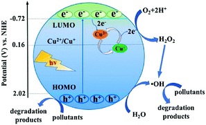 | ||
| Fig. 12 Proposed mechanism for electron transfer pathways during the degradation of pollutants by Cu doped NH2-MIL-125(Ti) under visible light. Adapted with permission from ref. 101, © 2018 Elsevier B. V. | ||
Besides, Ti substituted UiO-66–NH2(Zr) was achieved by a post-synthetic exchange method.94,95 The as-prepared UiO-66–NH2(Zr/Ti) exhibited enhanced photocatalytic performance for CO2 reduction and H2 production, which was ascribed to the presence of Ti4+ as an electron mediator. Furthermore, Yasin and co-workers carried out theoretical DFT calculations of band gaps for UiO-66–X (X: H, NO2 or NH2) with different ratios of mixed metallic centers (Zr, Ti or Hf).107 Results indicated that the band gap decreased gradually with increasing percentage of Ti4+ substitution. The lowest band gap (1.61 eV) was calculated on fully substituted Ti-BDC-NH2. Despite these, either the conventional solvothermal method or the post-synthetic exchange approach took too long time (up to days or even weeks).108 To overcome this barrier, a microwave-assisted method was recently developed due to much shorter reaction time and lower energy consumption.109,110 For example, Ti substituted UiO-66–NH2 could be fabricated within a few hours with well-maintained crystallinity and enhanced photocatalytic activity.
Similar to MOFs with mixed metals, MOFs with mixed linkers were also developed as unique photocatalysts. Using NH2-BDC and X-BDC (X: H, F, Cl, Br) as the primary and secondary linker, respectively, a series of Zr-based MOFs were synthesized in one-pot reactions.111 The introduction of X-BDC with an electron-withdrawing halogen group can lead to enhanced photocatalytic performance for alcohol oxidation, among which, Zr-MOF with NH2-BDC and F-BDC mixed linkers exhibited the highest performance.
By computational prediction, Grau-Crespo et al. reported a conceptually simple route to engineer the band edge positions of ZIFs using mixed organic linkers.112 As illustrated in Fig. 13A, a series of organic linkers were calculated. Relatively wide band gaps (>3.3 eV) can be observed using a single type of organic linker (Fig. 13B), indicating unachievable excitation by visible light. Whereas, the band gap dramatically decreased to 1.9 eV and 2.5 eV for ZnX2 by combining fIm or mIm with nIm linkers. The predicted band positions were theoretically ideal for visible light-induced CO2 reduction and water splitting. Moreover, they also calculated the influence of metal ion doping. Cu2+ doping would led to narrower band gaps with increased photo-absorption and e−–h+ recombination times, which was consistent with the experimental results in the mixed-metal strategy.
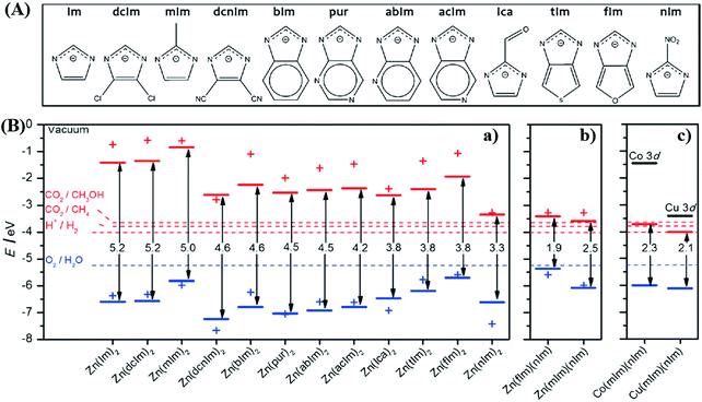 | ||
| Fig. 13 (A) The chemical structures of different organic linkers (X) for constructing ZnX2 MOFs; (B) calculated HOMO (blue) and LUMO (red) positions of ZnX2 crystal structures (lines) and isolated HX molecules (crosses): (a) ZnX2 with different combinations of organic ligands; (b) equivalent plot for ZnX2 created by combining fIm or mIm with nIm linkers; (c) equivalent plot for Co(mIm)(nIm) and Cu(mIm)(nIm). Adapted with permission from ref. 112, © 2016 Wiley-VCH. | ||
The combinations of mixed-metal and mixed-ligand strategies were also developed. For example, Amador et al. reported the synthesis of a UiO-67–Ru–Ti MOF through the combination of two pathways (Fig. 14).113 Firstly, 4,4′-biphenyldicarboxylic acid (BPDC) and Ru(Bpy)2(5,5′-dcbpy) were employed in the solvothermal process, which acted as the structure and light-absorbing antenna, respectively. Subsequently, Zr4+ was partially substituted by Ti4+via post-synthetic exchange. The as-prepared UiO-67–Ru–Ti MOF was evaluated by the degradation of MB dye. Dramatically enhanced performance can be observed under visible light relative to UiO-67–Ru or UiO-67–Ti with the single modification strategy.
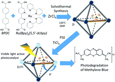 | ||
| Fig. 14 Schematic processes for preparing a UiO-67–Ru–Ti MOF and its application.113 Adapted with permission from ref. 113, © 2017 Elsevier B.V. | ||
3.3 Metal ion/ligand immobilization
In addition to functional group modification, implantation of transition metal ions to complex with ligands was reported to be a feasible way for enhanced photocatalytic performance.114,115 For example, the implantation of Fe3+ in porphyrinic MOFs (PCN-224) was achieved via a post synthetic reaction between pristine MOFs and FeCl3 in DMF solution.114 As illustrated in Fig. 15A, the unsaturated Fe3+ was implanted into the porphyrin unit, leading to the formation of Fe@PCN-224. The uniform distribution of Fe in FCN-224 can be further confirmed by HAADF-STEM (high-angle annular dark-field scanning TEM) and the corresponding elemental mapping images (Fig. 15B). After Fe3+ implantation, the optical response was extended to a longer wavelength, and the recombination of e−–h+ pairs was inhibited, which were revealed by UV-Vis Diffuse Reflectance Spectroscopy (UV-Vis-DRS), and photoluminescence (PL) and fluorescence lifetime measurements. Besides, the introduction of additional Fe3+ can also promote the activation of in situ generated H2O2, leading to more active O2˙− and HO˙ species. Thus, the photooxidation of gaseous isopropanol (IPA) was significantly boosted in Fe@PCN-224. The generation rate for the degradation intermediate (acetone) and product (CO2) exhibited an 8.9 and 9.3 times enhancement relative to pristine PCN-224, respectively (Fig. 15C and D). Good stability for Fe@PCN-224 can be deduced from cyclic experiments (Fig. 15E). Besides, this strategy was also applicable for the modification of another porphyrinic MOF (PCN-222), which exhibited similar behaviors. Different from the Fe(III) complex in the porphyrin unit, the immobilization of Bi(III) in MIL-101(Cr) via a two-step hydrolysis route led to the formation of small Bi-oxoclusters inside the mesocages of MIL-101.115 The complete photodegradation of methyl red (MR) can be easily achieved by the as-prepared Bi(III)@MIL-101(Cr) composite.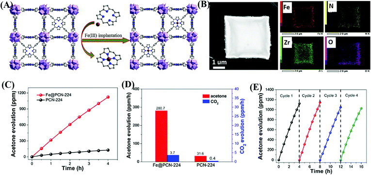 | ||
| Fig. 15 (A) Schematic illustration for implanting Fe3+ into the porphyrin unit of PCN-224; (B) HAADF-STEM image of Fe@PCN-224 and its corresponding elemental mapping images; (C) Time-dependent acetone evolution and (D) Evolution rate of acetone and CO2 during photocatalytic oxidation of IPA by PCN-224 and Fe@PCN-224; (E) cyclic photocatalytic evolution of acetone by Fe@PCN-224. Adapted with permission from ref. 114, © 2017 Elsevier B.V. | ||
Starting from the characteristics of pollutants, the implantation of appropriate substances that can accumulate pollutants on the surface or in the tunnel of MOFs has also been verified as an efficient method. For example, due to selective binding with radiative U(VI), phosphonate was previously verified as an efficient ligand for functional materials in adsorptive remediation of uranyl. Recently, Wang's group reported the post-synthetic modification of Zr-clusters in PCN-222 with aminomethylphosphonic acid (PN-PCN-222) and ethanephosphonic acid (P-PCN-222).116 It can be deduced from Fig. 16A that the morphology of PCN-222 was well maintained after ligand incorporation. Besides, phosphonic acids are chemically grafted onto the Zr clusters. Due to simultaneous selective complexation and photocatalytic reduction, U(VI) can be completely removed with an extremely wide concentration range (from 1 to 400 ppm). As shown in Fig. 16B, PN-PCN-222 (0.5 g L−1) exhibited the highest performance for U(VI) removal (756.1 mg g−1). At a lower catalyst dosage (0.25 g L−1), the uptake amounts for U(VI) were 184.2 and 1289.3 mg g−1 in the dark and under visible light, respectively. Moreover, PN-PCN-222 exhibited stable photocatalytic performance and recyclability for U(VI) removal (Fig. 16C).
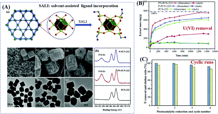 | ||
| Fig. 16 (A) Schematic representation for modification of PCN-222 (Zr: green; P: bottle green; C: cambridge blue; O: red; N: blue; H atoms are omitted) (a); SEM and the corresponding TEM images of PCN-222 (b, c), PNPCN-222 (c, f), and P-PCN-222 (d, g); XPS spectra of Zr(IV) in different samples (h); (B) uranium extraction (400 ppm) by different samples; (C) cyclic extraction efficiency of U (10 ppm) via a photoreduction method (left axis) and elution 0.1 M HCl (right axis). Adapted with permission from ref. 116, © 2019 Elsevier B.V. | ||
3.4 Dye sensitization
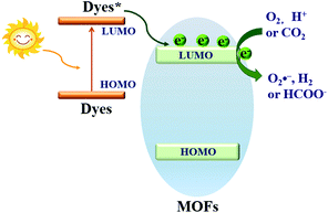
Dye sensitization is a mature way for harvesting more incident solar light, which is well known in dye-sensitized solar cells (DSSCs). Different from the traditional semiconductor-based system, a strong π–π stacking as well as van der Waals interaction may be expected in dye-sensitized MOFs due to the extensive presence of benzene rings in the organic linker of both MOFs and dyes. Inspired by this, dye-sensitized photocatalysis was further developed using MOFs as the substrate. Specific dyes can be selected to form a complex with MOFs. As shown in Fig. 17, dye molecules in the ground state can absorb incident light and be transformed into the excited state (dye*). As long as the potential of dye* is more negative than the LUMO position of MOFs, electron injection from dye* to the LUMO of MOFs will be feasible. Finally, the electrons can be transferred to different acceptors (O2, H+ or CO2) leading to the formation of active O2˙−, H2 or HCOO−, respectively. In this way, the excitation wavelength can be extended to visible light. At the beginning, many researchers were focused on H2 production and CO2 reduction.75,117–122 Recently, dye-sensitized MOFs were gradually applied in the field of environmental remediation.123–126For example, zinc phthalocyanine (ZnTCPc) was applied to form a complex with UiO-66 and UiO-66(NH2) via an impregnation method.124 As shown in Fig. 18, in comparison with pristine MOFs, both the ZnTCPc modified samples displayed enhanced visible light activity for MB degradation. Besides, due to the synergistic effect of visible light-responsive UiO-66(NH2), the degradation efficiency increased from 68% by ZnTCPc/UiO-66(Zr) to 89% by ZnTCPc/UiO-66(NH2) after 120 min visible light irradiation. In addition to metal–organic ZnTCPc dye, Thakare and Ramteke reported the post-modification of MOF-5 using 8-hydroxyquinoline (HOQ) dye for the degradation of colorless phenol.123 After 80 min visible light irradiation, phenol (1 mg L−1) can be completely degraded using HQQ/MOF (4 g L−1) as a photocatalyst. Whereas, less than 5% phenol was degraded using unmodified MOF-5, indicating the vital role of HQQ dye. Moreover, the photocatalytic performance remained well up to 5 cyclic runs. No difference was observed in both XRD and UV-Vis-DRS analyses, indicating the stability of the HQQ/MOF-5 composite. Besides, Rhodamine B (RhB) dye, which was frequently reported as a target dye pollutant, was also applied to sensitize MIL-125(Ti) via a post-impregnation method.127 For the degradation of MO dye, boosted performance was observed from inactive MIL-125(Ti) to more than 90% on RhB/TiO2 after 60 min visible light irradiation. Trichromatic dyes, such as Basic Yellow 24 (BY24), Basic Red 14 (BR14) or Methylene Blue (MB), were also encapsulated in Cu-MOFs. The as-prepared dye@Cu-MOFs all exhibited enhanced performance for the degradation of large sized Reactive Blue 13 (RB13). Among which, MB@Cu-MOFs displayed the highest activity. The reason was ascribed to the difference in the visible light-absorption region. For example, MB covers 450–750 nm, which is broader than that of BR14 (380–580 nm) and BY24 (325–480 nm).
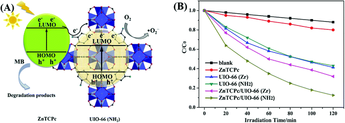 | ||
| Fig. 18 (A) Proposed mechanism for the degradation of MB by ZnTCPc/UIO-66(NH2) under visible light; (B) degradation dynamics of MB by different samples. Adapted with permission from ref. 124, © 2016 Elsevier B.V. | ||
3.5 Metal nanoparticle loading
Due to the porous characteristics, photoactive guest species can be incorporated into the pore spaces or partially stabilized on the surface of MOFs. Metal nanoparticles (MNPs), especially small noble MNPs with structural diversity and tailoring ability, are promising guest species. As a typical design, the encapsulation of MNPs into the cavity of MOFs can regulate the size and enhance the stability of MNPs. Up to now, the MNP/MOF composites have shown great potential in photocatalysis.29,128–131 Herein, due to low Fermi energy levels, the MNP co-catalysts were reported to serve as electron acceptors and mediators. Sometimes, they can also enhance the visible and/or NIR light absorption. For example, due to the localized surface plasmon resonance (LSPR) effect, the loading of noble MNPs led to enhanced visible light absorption and excitation.132–134For photocatalytic elimination of environmental pollutants, Pd nanoparticles (3 to 6 nm in diameter) were immobilized and highly dispersed in NH2-UiO-66(Zr) via a one-pot hydrothermal method. The as-prepared Pd@NH2-UiO-66(Zr) composite displayed reusable and highly enhanced photocatalytic activity for Cr(VI) reduction.135 As listed in Table 3, at a catalyst dosage of 0.5 g L−1 and after 90 min visible light irradiation, the removal efficiency for Cr(VI) increased from 33% to 99% after Pd loading. Besides, the BET surface area slightly increased from 756 to 837 m2 g−1, indicating more surface active sites. Moreover, the addition of an organic dye (MB or MO) can further promote the reduction of Cr(VI). In this way, dye oxidation and Cr(VI) reduction can be simultaneously achieved by photogenerated electrons (e−) and holes (h+), respectively.
| MNPs/MOF | S BET variationa (m2 g−1) | Pollutant | C pollutant (mg L−1) | C catalyst (g L−1) | Time (min) | η variationb (%) | Ref. |
|---|---|---|---|---|---|---|---|
| NA: no experimental data available.a SBET variation indicates the surface area of MOFs before and after loading MNPs.b Removal efficiencies (η) for pollutants are used as received or estimated from the figures in the reference and presented in integer numbers; η variation indicates the performance of MOFs before and after loading MNPs.c Addition of H2O2.d Addition of ammonium oxalate.e UV-Vis light or solar light.f In acetonitrile with the addition of TEOA.g 100 W daylight lamp. | |||||||
| Pd@NH2-UiO-66(Zr) | 756 → 837 | Cr(VI) | 10 | 0.5 | 90 | 36 → 99 | 135 |
| Pd@MIL-100(Fe) | 2006 → 2102 | Theophyllinec | 20 | 0.125 | 150 | 82 → 100 | 136 |
| Ibuprofenc | 20 | 0.125 | 150 | 67 → 100 | |||
| Bisphenol Ac | 20 | 0.125 | 240 | 35 → 66 | |||
| Pd@MIL-100(Fe) | 2007 → 1898 | MOc | 20 | 0.125 | 40 | 41 → 84 | 137 |
| Cr(VI)d | 20 | 1.0 | 8 | 69 → 100 | |||
| Pt@MIL-100(Fe) | 2007 → 1724 | MOc | 20 | 0.125 | 40 | 41 → 100 | 137 |
| Cr(VI)d | 20 | 1.0 | 8 | 69 → 86 | |||
| Pt/NH2-MIL-125(Ti) | 1052 → 896 | Cr(VI) | 15 | 1.0 | 120 | 41 → 77e | 138 |
| Pt/NH2-MIL-125(Ti) | 1101 → 910 | Nitrobenzenef | 3075 | 6.25 | 1200 | NA → 98 | 139 |
| Au@MIL-100(Fe) | 2007 → 1822 | MOc | 20 | 0.125 | 40 | 41 → 65 | 137 |
| Cr(VI)d | 20 | 1.0 | 8 | 69 → 82 | |||
| Ag@MOF-5 | NA | E. coli | NA | NA | 70 | 28 → 91 | 34 |
| Ag@MIL-125(Ti) | NA | RhB | NA | 1.0 | 40 | 8 → 93 | 140 |
| Ag/MIL-125(Ti)-AC | 1245 → 977 | MB | 20 | 0.06 | 30 | 55 → 100g | 141 |
| Ag/UiO-66–NH2 | NA | Cr(VI) | 10 | 1.0 | 105 | 40 → 90 | 142 |
| PtPd@ZIF-8 | 1024 → 713 | C2H4 | 100 | NA | 120 | <5 → 93e | 143 |
| CuPd@ZIF-8 | 1531 → 1259 | Cr(VI) | 20 | 0.2 | 60 | 22 → 89e | 144 |
Furthermore, Pd@MIL-100(Fe) with a higher surface area was also fabricated (2102 m2 g−1).145 As shown in Fig. 19A and B, using H2PdCl4 as the precursor, 1 wt% Pd nanoparticles (6 to 10 nm in diameter) with high dispersion were anchored on MIL-100(Fe) via a facile alcohol reduction method. The as-prepared brown Pd@MIL-100(Fe) powder displayed slightly enhanced absorption in the visible light region relative to the unmodified one. For the photocatalytic degradation of pharmaceuticals and personal care products (PPCPs), such as theophylline, ibuprofen and bisphenol A, Pd@MIL-100(Fe) displayed superior photocatalytic activity (Fig. 19C). The enhanced photocatalytic performance was ascribed to more efficient separation of photogenerated e−–h+ pairs and easier transfer of interfacial charges induced by Pd loading. To gain more insight into the reaction, trapping experiments using different radical scavengers were further carried out, and the results indicated that HO˙ played a major role for PPCP degradation. Thus, a proposed mechanism is given in Fig. 19D.
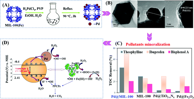 | ||
| Fig. 19 (A) Schematic processes for preparing Pd@MIL-100(Fe) via a facile alcohol reduction method; (B) TEM and HRTEM images of Pd@MIL-100(Fe); (C) TOC removal efficiency of theophylline, ibuprofen and bisphenol A by different photocatalysts. Reaction conditions: 5 mg photocatalyst, 40 mL PPCPs (20 mg L−1), 40 μL H2O2, pH 4; (D) proposed mechanism for visible-light-induced PPCP degradation by Pd@MIL-100(Fe). Adapted with permission from ref. 145, © 2015 Elsevier B.V. | ||
Furthermore, Wu's group prepared a series of M@MIL-100(Fe) (M: Au, Pd or Pt) via a photochemical route and compared their photocatalytic performance under visible light.137 Metal ion precursors can capture the photogenerated electrons in the LUMO of MIL-100(Fe), leading to the reduction and deposition of the corresponding MNPs on the MIL-100(Fe) substrate. The average diameters were estimated to be 15, 12 and 2 nm for Au, Pd and Pt nanoparticles, respectively (Fig. 20A). The as-prepared M@MIL-100(Fe) was compared for the photocatalytic removal of MO and Cr(VI) under visible light. Enhanced photocatalytic activity can be observed after loading different kinds of MNPs, among which Pt loading exhibited the highest performance. The order of Pt@MIL-100(Fe) > Pd@MIL-100(Fe) > Au@MIL-100(Fe) > MIL-100(Fe) was consistent with the results of visible light absorption and photocurrent response (Fig. 20B and C), but in the reverse order of the surface area. Therefore, the presence of noble MNPs plays a crucial role in enhancing visible light absorption and prolonging the lifetime of photogenerated charges, which together lead to boosted photocatalytic performance for the removal of environmental pollutants.
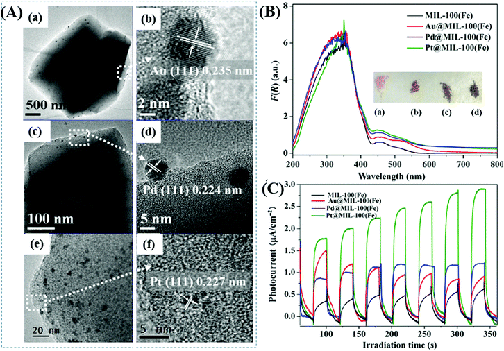 | ||
| Fig. 20 (A) TEM and the corresponding HRTEM images of (a, b) Au@MIL-100(Fe); (c, d) Pd@MIL-100(Fe); (e, f) Pt@MIL-100(Fe); (B) UV-vis DRS spectra and (C) photocurrent response of MIL-100(Fe) and M@MIL-100(Fe). Adapted with permission from ref. 137, © 2015 Springer. | ||
Ag nanoparticles are also excellent electron sinks due to the formation of Ag-MOF Schottky junctions at the interface. Thus, the e−–h+ recombination in MOFs can be greatly inhibited, leading to enhanced photocatalytic activity after loading Ag nanoparticles. For example, Ag@MIL-125(Ti) was fabricated through a facile photo-reduction method. The AgNO3 precursor can be photo-reduced to uniform Ag nanoparticles (∼40 nm) and loaded onto the surface of MIL-125(Ti). After 40 min of visible-light irradiation, about 8% RhB was degraded by pure MIL-125(Ti), whereas, the value was boosted to 93% by Ag@MIL-125(Ti).140 Simultaneously, the post-synthetic modification of NH2-MIL-125(Ti) with acetylacetone (AC) led to the formation of MIL-125-AC, which was subsequently treated with CH3COOAg.141 In this way, smaller Ag nanoparticles, mostly 5–10 nm in size, were spread on the external surface and embedded within NH2-MIL-125(Ti). The as-prepared Ag/MIL-125(Ti)-AC displayed enhanced activity for photocatalytic degradation of MB dye.
In addition to single MNPs, bimetallic alloy nanocrystals were also encapsulated in MOFs for photocatalytic applications. For example, PtPd alloy nanocrystals were encapsulated in microporous ZIF-8 with high dispersion (Table 3). Superior activity for the degradation of ethylene to CO2 can be achieved.143 Recently, CuPd alloy nanoparticles was dispersed on ZIF-8 with good stability for Cr(VI) reduction.144 As shown in Fig. 21, CuPd@ZIF-8 was fabricated via a sol–gel method. Compared with pristine ZIF-8, the loading of CuPd alloy led to enhanced adsorption capacity for O2 and more photogenerated e−–h+ pairs due to the LSPR effect. Upon light irradiation, the photogenerated e− can be directly transferred to Cr(VI) or O2. Despite the competition of O2 in capturing e−, the reduction product of O2 (O2˙−) will also contribute to Cr(VI) reduction, which would finally led to boosted photocatalytic activity. After 60 min visible light irradiation, the efficiency of Cr(VI) reduction increased from 22% on pristine ZIF-8 to 89% on optimized CuPd@ZIF-8 with 5 wt% CuPd. Moreover, other control samples were also tested, which were in the order of CuPd@ZIF-8 > Cu@ZIF-8 > Pd@ZIF-8 > ZIF-8 > CuPd > Pd > Cu. Obviously, the CuPd alloy displayed a synergistic effect compared to single MNPs. Besides, the stability of the optimized CuPd@ZIF-8 was maintained well (>90%) after four successive cyclic runs.
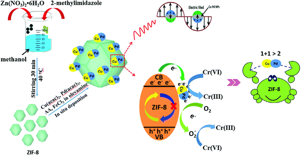 | ||
| Fig. 21 Schematic processes for preparing CuPd@ZIF-8 and the proposed mechanism for photocatalytic reduction of Cr(VI). Adapted by permission of ref. 143, © 2014 The Royal Society of Chemistry. | ||
3.6 Carbon material decoration
In traditional semiconductor photocatalytic systems, carbon materials with superior electrical conductivity were widely applied to form hybrid photocatalysts. The recombination of photogenerated charges can be suppressed after the loading of carbon materials.146–148 For example, graphene oxide (GO), reduced graphene oxide (rGO), carbon quantum dots (CQDs), etc. were typical carbon materials, which could accelerate the transfer of photogenerated charges. Similarly, coupling carbon materials with MOFs will also solve the disadvantages of fast charge recombination in pristine MOFs, and lead to enhanced photocatalytic performance. As listed in Table 4, some typical carbon-MOF composites were fabricated. No matter whether the specific surface area (SBET) is increased or decreased, carbon coupling led to boosted photocatalytic performance for the elimination of environmental pollutants.| MOF-based composite | Carbon materials (wt%) | S BET variationa (m2 g−1) | Pollutant | C pollutant (mg L−1) | C catalyst (g L−1) | Time (min) | η variationb (%) | Ref. |
|---|---|---|---|---|---|---|---|---|
| NA: no experimental data available; rGO: reduced graphene oxide; GO: graphene oxide; CQDs: carbon nanodots; FCF: functional carbon fiber; ptz: 5-(4-pyridyl)-1H-tetrazole.a SBET variation indicates the surface area of MOFs before and after loading carbon materials.b Removal efficiencies (η) for pollutants are used as received or estimated from the figures in the reference and presented in integer numbers; η variation indicates the performance of MOFs before and after loading carbon materials.c Addition of ammonium oxalate.d Addition of H2O2.e UV-Vis light or sunlight.f Vol%. | ||||||||
| MIL-53(Fe) | 2.5% rGO | NA | MB | 20 | 0.5 | 80 | 82 → 95 | 149 |
| MIL-53(Fe) | 0.5% rGO | NA | Cr(VI)c | 20 | 1.0 | 80 | 79 → 100 | 150 |
| NH2-MIL-68(In) | GO | 530 → 681 | AMX | 20 | 0.6 | 10 | 60 → 93 | 151 |
| MIL-88B(Fe) | 10% GOc | NA → 99 | RR195d | 100 | 0.3 | 20 | 50 → 95e | 152 |
| MIL-88(Fe) | 3% GOc | NA | MB | 100 | 0.5 | 10 | 48 → 95e | 153 |
| RhB | 49 → 94e | |||||||
| NH2-MIL-125(Ti) | 10% GO | 871 → 501 | NO | 0.5 | 5 | 30 | 30 → 50 | 154 |
| CH3CHO | 1.95 | 50 | 80 | 48 → 65 | ||||
| NH2-MIL-125(Ti) | 1% CQDs | 487 → 198 | RhB | 10 | 0.5 | 240 | 67 → 100 | 155 |
| NH2-UiO-66(Zr) | 2% rGO | 732 → 767 | Cr(VI) | 10 | 0.5 | 100 | 35 → 100 | 156 |
| ZIF-8 | 2.5% CQDsf | 1356 → 1479 | NO | 0.42 | 10 | 30 | 0 → 43 | 157 |
| [Cu2Br(ptz)]n | 20% FCF | NA | RhB | 4.8 | 0.25 | 180 | 3 → 88 | 158 |
For example, MIL-53(Fe)/rGO hybrid materials were prepared via a simple one-step solvothermal method. With an optimal loading amount of rGO (2.5 wt%), the degradation of MB dye can be increased.149 Besides, Li et al. reported the fabrication of GO modified NH2-MIL-125(Ti) with enhanced performance for photocatalytic degradation of gaseous pollutants. The light absorption, charge generating and transfer properties of NH2-MIL-125(Ti) can be greatly altered after GO coupling. For example, the light absorption was greatly enhanced in the region of 200–500 nm, and the absorption edge was also shifted from 445 to 455 nm due to strong interaction between GO and NH2-MIL-125(Ti). Moreover, the charge transfer resistance was also decreased (Fig. 22A), and the photocurrent response under visible light was dramatically increased (Fig. 22B). Due to the above combined effects, both photocatalytic oxidation of NO and degradation of acetaldehyde were greatly accelerated in optimized GO/NH2-MIL-125(Ti) relative to pristine NH2-MIL-125(Ti) (Fig. 22C and D). For better understanding, the proposed mechanism is depicted in Fig. 22E. Namely, upon visible light irradiation, the organic linker (2-aminoterephthalic acid) can be excited and generate electrons which will be transferred to the center of the Ti–O cluster. In this way, the photoexcited electrons will be trapped on metallic Ti by reducing Ti4+ to Ti3+. The presence of GO can rapidly accumulate the trapped electrons and accelerate their transfer to O2. Thus, more reactive O2˙− radicals can be generated, which will be beneficial for the degradation of gaseous pollutants.
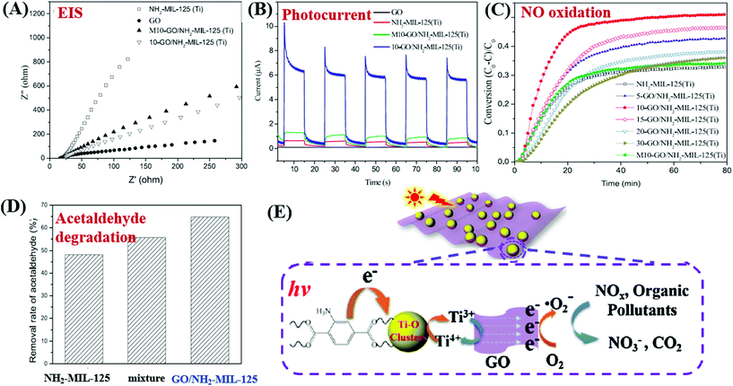 | ||
| Fig. 22 Comparison of NH2-MIL-125(Ti) and GO/NH2-MIL-125(Ti): (A) EIS Nyquist plots and (B) photo-current responses; (C) photocatalytic oxidation of NO; (D) photocatalytic degradation of acetaldehyde; (E) proposed mechanism for pollutant degradation by GO/NH2-MIL-125(Ti) under visible light irradiation. Adapted with permission from ref. 154, © 2018 Elsevier B.V. | ||
As a novel carbon nanomaterial, CQDs were also applied to couple with MOFs. In addition to the beneficial properties of good electron conductivity, easy functionalization, low cost and low toxicity, CQDs have special optical properties in upconversion luminescence.159–161 The incident near infrared light can be absorbed by CQDs and then converted to visible light which will enhance the utilization of solar energy.162 As shown in Fig. 23A, CQDs with a size of 2 nm were successfully distributed on NH2-MIL-125(Ti) via a simple solvent-deposition method.163 The large surface area of NH2-MIL-125(Ti) (487 m2 g−1) was beneficial for CQD loading. For the photocatalytic degradation of RhB dye (Fig. 23B), the as-prepared CQD/NH2-MIL-125 composite always exhibited enhanced performance, no matter the incident light is full spectrum, visible light or near-infrared light. The highest activity was observed at a loading amount of 1 wt% CQDs. Meanwhile, good stability of the optimized CQD/NH2-MIL-125 can be maintained after 7 successive cyclic runs. For better understanding of the photocatalytic mechanism, photoluminescence (PL) spectra and electrochemical impedance spectroscopy (EIS) Nyquist plots were obtained to investigate the separation efficiency and transfer resistance of photogenerated charge carriers, respectively. Moreover, the upconversion PL spectra were also obtained to detect the unique PL upconversion performance of CQDs. Based on the above results, the mechanisms for charge generation, separation and transfer in CQD/NH2-MIL-125(Ti) were proposed (Fig. 23C). Under visible light (λ > 420 nm) irradiation, the good electron conductivity of CQDs can facilitate efficient separation of photogenerated e−–h+ pairs in NH2-MIL-125(Ti). Under near-infrared light (λ > 700 nm) irradiation, in addition to electron conductivity, the special upconversion luminescence properties of CQDs can convert near infrared light into visible light, leading to more efficient utilization of solar energy.
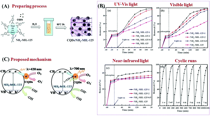 | ||
| Fig. 23 (A) Schematic processes for preparing CQD/NH2-MIL-125(Ti); (B) photocatalytic degradation of RhB by NH2-MIL-125 and CQD/NH2-MIL-125 composites under the irradiation of (a) full spectrum light, (b) visible light and (c) near-infrared light; (d) cyclic runs for RhB degradation by optimized CQD/NH2-MIL-125 under full spectrum light; (C) proposed mechanism for charge transfer in CQD/NH2-MIL-125(Ti) under visible light (λ > 420 nm) and near-infrared light (λ > 700 nm) irradiation; adapted with permission from ref. 155, © 2018 Elsevier B.V. | ||
As another attractive option, functional carbon fiber (FCF) has several merits, such as high conductivity, large surface area and excellent absorption capability. In particular, FCF can act as a photosensitizer to extend the photoresponse. For example, a new coordination polymer [Cu2Br(ptz)]n (CP) (ptz = 5-(4-pyridyl)-1H-tetrazole) nanobelt (CPNB) was loaded on the surface of FCF via a simple colloidal blending process.158 The resulting CPNB/FCF composite exhibited significantly enhanced activity for photocatalytic degradation of RhB. At a catalyst dosage of 0.25 g L−1 and after 180 min visible light irradiation, the removal efficiency for RhB dramatically increased from 3% using pristine CPNB to 88% using the CPNB/FCF composite. As shown in Fig. 24A, the band gap (Eg) of pristine CPNB was 3.17 eV, and it decreased to 2.02–2.69 eV after loading FCF with different pretreatment times. Moreover, results from both photocurrent response and EIS Nyquist plots indicated the merits of loading FCB (Fig. 24B and C). Considering the flat band potential in the Mott–Schottky plot (Fig. 24C) and the Eg (3.17 eV), the CB and VB positions of CPNB were estimated to be −0.31 V and +2.86 V (vs. SCE), respectively. Under visible light irradiation, only FCF can be excited (Fig. 24D). The photogenerated electrons will transfer from the CB of FCF to CPNB, leading to an effective separation of e−–h+ pairs.
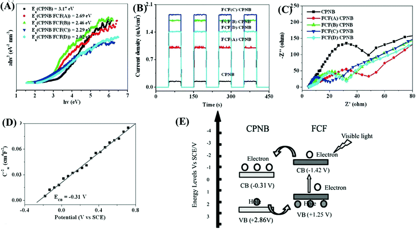 | ||
| Fig. 24 Comparison between CPNB and CPNB/FCF: (A) Tauc plots; (B) photocurrent response; (C) EIS Nyquist plots; (D) Mott–Schottky plot of CPNB; (E) proposed photocatalytic mechanism for CPNB/FCF. Adapted with permission from ref. 158, © 2015 Wiley-VCH. | ||
3.7 MOF-semiconductor heterojunctions
Coupling MOFs with other photoactive semiconductors was another alternative way to enhance the photocatalytic activity. In this approach, the porous network of MOFs can facilitate the dispersion of semiconductors, generating more active sites. Moreover, due to the formation of heterojunctions,164 more efficient separation of photo-excited charges can be achieved. Typically, there are three types of heterojunctions for semiconductors, depending on the CB/VB position as well as the n/p type nature of independent components (Fig. 25). Until now, many semiconductors have been reported to form composites with MOFs. For example, metal-containing semiconductors (such as ZnO, TiO2, BiVO4, AgI, α-Fe2O3, CdS, etc.) and nonmetal graphitic carbon nitride (g-C3N4) have been coupled with photoactive MOFs and exhibited superior performance in the field of photocatalysis.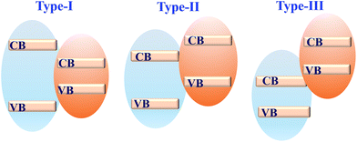 | ||
| Fig. 25 Three types of semiconductor heterojunctions. Type-I: straddling gap; type-II: staggered gap; type-III: broken gap. | ||
| Composites | S BET variationa (m2 g−1) | Pollutant | C pollutant (mg L−1) | C catalyst (g L−1) | Time (min) | η variationb (%) | Ref. |
|---|---|---|---|---|---|---|---|
| NA: no experimental data available.a SBET variation indicates the surface area of MOFs before and after forming composites.b Removal efficiencies (η) for pollutants are used as received or estimated from the figures in the reference and presented in integer numbers; η variation indicates the performance of MOFs before and after forming composites.c Addition of H2O2.d UV-Vis light or simulated sunlight.e Addition of ammonium oxalate.f 500 nm monochromatic light.g Under the assistance of sonication.h 465 nm LED light. | |||||||
| Coupled with Zn-MOFs | |||||||
| BiOBr/MOF-5(IL) | 915 → NA | MO | 10 | 0.4 | 150 | <2 → 88 | 168 |
| TiO2@ZIF-8 | NA | MB | 1.6 | NA | 120 | 54 → 88d | 169 |
| RhB | 2.4 | NA | 120 | 50 → 65d | |||
| Bi2MoO6/ZIF-8 | NA | MB | 20 | 0.25 | 100 | 34 → 67 | 170 |
| 3D MoO3@ZIF-8 | 1531 → 213 | Cr(VI) | 15 | 0.5 | 40 | 13 → 96 | 171 |
| MoO3-NPs/ZIF-8 | 1710 → 1529 | MB | 10 | 0.25 | 180 | 59 → 82d | 172 |
| BiFeO3/ZIF-8 | NA | MB | 20 | 0.375 | 100 | 50 → 93 | 173 |
| ZIF-8@BiVO4 | 1180 → 249 | MB | 20 | 0.25 | 130 | NA → 81d | 174 |
| Bi2S3@ZIF-8 | 1297 → 821 | RhB | 10 | 0.4 | 90 | NA → 97 | 175 |
| Cd0.5Zn0.5S@ZIF-8 | 1190 → 174 | Cr(VI) | 20 | 1 | 10 | 5 → 100 | 176 |
| Coupled with Fe-MOFs | |||||||
| Fe2O3/MIL-53(Fe) | 48 → 47 | MB | 10 | 0.2 | 120 | 31 → 48 | 177 |
| WO3/MIL-53(Fe) | 57 → 97 | Cr(VI) | 30 | 1.5 | 240 | 70 → 94d | 167 |
| 2,4-D | 30 | 1.5 | 240 | 58 → 100d | |||
| Ag3PO4/MIL-53(Fe) | 9 → 16 | TC | 20 | 0.5 | 60 | 26 → 94 | 165 |
| AgI/MIL-53(Fe) | NA | RhB | 4.8 | 0.3 | 45 | 86 → 99 | 166 |
| CdS/MIL-53(Fe) | NA | RhB | 10 | 1.0 | 120 | 5 → 86 | 178 |
| 1T-MoS2/MIL-53(Fe) | 21 → 337 | IBPc | 10 | 0.4 | 120 | 50 → 100 | 179 |
| MIL-53(Fe)/SnS | 56 → 34 | Cr(VI) | 20 | 1.0 | 60 | 16 → 71 | 180 |
| TiO2@NH2-MIL-88B(Fe) | 34 → 19 | Cr(VI)e | 10.4 | 0.5 | 35 | 85 → 99d | 181 |
| TiO2NS@MIL-100(Fe) | 1670 → 474 | MBc | 50 | 0.2 | 60 | NA → 96 | 182 |
| MIL-100(Fe)/TiO2 | 1189 → 307 | TCc | 100 | 0.05 | 60 | NA → 86d | 183 |
| Cr(VI) | 10 | 0.05 | 60 | NA → 50d | |||
| N-TiO2QDs/MIL-100(Fe) | 1556 → 1413 | MB | 16 | 0.1 | 140 | 90 → 99 | 184 |
| RhB | 24 | 0.1 | 140 | 83 → 94 | |||
| M.MIL-100(Fe)@ZnO | 766 → 654 | Phenol | 5 | 0.2 | 120 | 43 → 85 | 185 |
| BPA | 5 | 0.2 | 120 | 35 → 89 | |||
| Atrazine | 5 | 0.2 | 120 | 30 → 70 | |||
| Bi2WO6/MIL-100(Fe) | 1370 → 140 | SAc | 10 | 1.0 | 50 | 35 → 95 | 186 |
| Bi2MoO6/MIL-100(Fe) | NA → 110 | RhB | 10 | 1.0 | 120 | 51 → 88 | 187 |
| MIL-100(Fe)@Bi2S3 | 1394 → 404 | RhB | 10 | 0.5 | 60 | 70 → 94 | 188 |
| M-MIL-101(Fe)/TiO2 | 394 → 159 | TC | 20 | 1.0 | 80 | 74 → 92 | 189 |
| Coupled with Cr-MOFs | |||||||
| N-K2Ti4O9/MIL-101(Cr) | 2321 → 135 | RhB | 5 | 0.2 | 180 | 43 → 54d | 190 |
| WO3@MIL-101(Cr)@WO3 | 2480 → 1360 | MB | 30 | NA | 80 | NA → 100 | 191 |
| Coupled with Zr-MOFs | |||||||
| Ag2CO3/UiO-66(Zr) | 808 → 522 | RhB | 14.4 | 0.5 | 120 | NA → 94 | 192 |
| AgI/UiO-66(Zr) | 808 → 289 | RhB | 14.4 | 0.5 | 60 | NA → 100 | 193 |
| N-K2Ti4O9/NH2-UiO-66(Zr) | NA | RhB | 5 | 0.2 | 180 | 53 → 90d | 194 |
| MB | 5 | 0.2 | 180 | NA → 94d | |||
| NR | 5 | 0.2 | 180 | NA → 91d | |||
| BiOBr/UiO-66(Zr) | 869 → 204 | RhB | 14.4 | 0.5 | 15 | <5 → 98 | 195 |
| BiOBr/NH2-UiO-66(Zr) | NA | Noroxin | 0.3 | 0.3 | 180 | 34 → 94d | 196 |
| α-Fe2O3@UiO-66(Zr) | 1296 → 1204 | MB | 12.8 | 1.0 | 50 | 70 → 100 | 197 |
| WO2.72/UiO-66(Zr) | 1099 → 187 | MO | 20 | 0.3 | 60 | 48 → 100 | 198 |
| BiVO4/UiO-66(Zr) | 646 → 387 | RhB | 10 | 1.0 | 150 | <10 → 100 | 199 |
| Bi2WO6/UiO-66(Zr) | 808 → 275 | RhB | 14.4 | 0.5 | 180 | NA → 100 | 200 |
| Bi2MoO6/UiO-66(Zr) | 621 → 209 | RhB | 10 | 0.5 | 120 | 30 → 92 | 201 |
| ZnIn2S4/UiO-66(Zr) | 911 → 242 | Cr(VI) | 80 | 0.5 | 60 | <5 → 99 | 202 |
| MO | 20 | 0.17 | 180 | 49 → 98 | |||
| CdS@NH2-UiO-66(Zr) | 840 → 114 | MG | 20 | 0.2 | 30 | 16 → 100 | 203 |
| Coupled with Ti-MOFs | |||||||
| In2S3@MIL-125(Ti) | 1548 → 304 | TC | 46 | 0.3 | 60 | 42 → 63 | 204 |
| BiOBr/NH2-MIL-125(Ti) | 1012 → 8 | RhB | 20 | 0.2 | 100 | 41 → 98 | 205 |
| Phenol | 20 | 0.2 | 150 | NA → 24 | |||
| BiOI/NH2-MIL-125(Ti) | NA | MO | 20 | 1.0 | 120 | 22 → 93 | 206 |
| NH2-MIL-125(Ti)/BiOCl | 770 → 46 | TC | 20 | 0.5 | 120 | 5 → 78 | 207 |
| BPA | 10 | 0.5 | 240 | NA → 65 | |||
| Ag3PO4/NH2-MIL-125(Ti) | NA | MB | 10 | 0.5 | 50 | 55 → 100 | 208 |
| RhB | 10 | 0.5 | 180 | 50 → 94 | |||
| PHIK/NH2-MIL-125(Ti) | 1160 → 185 | RhB | 100 | 1.0 | 120 | 66 → 97h | 209 |
| CdTe QDs/NTU-9 | 1205 → 880 | Rh6G | 1.0 | 0.05 | 30 | 55 → 96f | 210 |
| Coupled with Cu-MOFs | |||||||
| HKUST-1/BiVO4 | 855 → 585 | DB17 | 30 | 0.2 | 20 | NA → 100g | 211 |
| RB | 30 | 0.2 | 20 | NA → 99g | |||
| Cu2(OH)PO4-HKUST-1 | NA | Abamectin | 30 | 0.4 | 20 | NA → 100g | 212 |
| Coupled with other MOFs | |||||||
| Co,Ni-MOF/BiFeO3 | 1058 → 895 | MO | 50 | 0.2 | 90 | 34 → 94 | 213 |
| 4-NP | 50 | 0.2 | 90 | 24 → 75 | |||
| Co,Ni-MOF/CuWO4 | 1054 → 801 | MB | 10 | 0.2 | 135 | 32 → 98 | 214 |
| 4-NP | 10 | 0.2 | 105 | 24 → 81 | |||
| Ag3PO4@Co,Ni-MOF | NA | Phenol | 40 | 1.0 | 16 | <5 → 100 | 215 |
| BPA | 40 | 1.0 | 20 | <5 → 99 | |||
| BiOBr/CAU-17 | NA | RhB | 20 | 0.2 | 40 | 22 → 99 | 216 |
For example, Ag3PO4@NH2-MIL-125(Ti) was fabricated via a simple drying process.208 As shown in Fig. 26A, Ag3PO4 nanoparticles (10 to 20 nm) were well-dispersed onto the surface of NH2-MIL-125(Ti). The band structures of Ag3PO4 and NH2-MIL-125(Ti) are illustrated in Fig. 26B, which indicates a Type I heterojunction. The as-prepared binary composite exhibited significantly enhanced performance (Fig. 26C) as well as good stability for MB degradation under visible light irradiation. Similarly, WO2.72/UiO-66(Zr)198 and Co,Ni-MOF/BiFeO3![[thin space (1/6-em)]](https://www.rsc.org/images/entities/char_2009.gif) 213 composites were also prepared and displayed characteristic properties of Type I heterojunctions.
213 composites were also prepared and displayed characteristic properties of Type I heterojunctions.
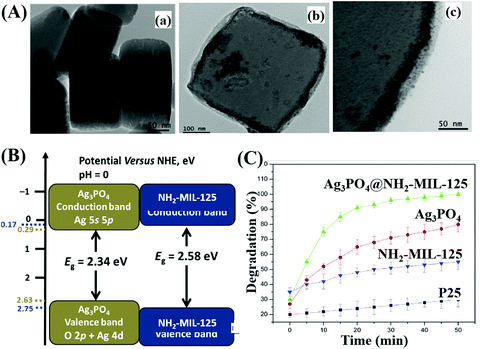 | ||
| Fig. 26 (A) TEM images of NH2-MIL-125(Ti) (a), Ag3PO4@NH2-MIL-125(Ti) (b), and high magnification of Ag3PO4@NH2-MIL-125(Ti) (c); (B) CB and VB positions of Ag3PO4 and NH2-MIL-125 (Ti); (C) photocatalytic degradation of MB by different samples under visible light irradiation. Adapted with permission from ref. 208, © 2017 Elsevier B.V. | ||
Due to the water-stability of UiO-66(Zr), the UiO-66(Zr)-based composites were competitive candidates for wastewater treatment. For example, BiOBr/UiO-66(Zr) was prepared by incorporating UV-active UiO-66 (Eg = 4.0 eV) with visible light-active BiOBr (Eg = 2.8 eV) through a convenient solution method.195 The as-prepared BiOBr/UiO-66 composite displayed enhanced photocatalytic activity for RhB degradation, as well as good stability in cyclic runs. After 15 min visible light irradiation, the removal efficiency of RhB was in the order of BiOBr/UiO-66 (100%) > BiOBr (84%) > UiO-66(Zr) (<5%). Furthermore, amine-functionalized UiO-66 was also applied to couple with BiOBr.196 As shown in Fig. 27A, a flower-like BiOBr/NH2-UiO-66(Zr) composite with a three-dimensional structure was fabricated. Intensive characterization by SEM, XRD and XPS has been carried out to investigate the structure properties. Results indicated that BiOBr nanoplates successfully grew on the surface of NH2-UiO-66(Zr) with an intimate interaction. The recombination of charge carriers can be inhibited, which was evidenced by the PL spectra. For the photocatalytic degradation of a typical fluoroquinolone antibiotics (norfloxacin), the as-prepared BiOBr/NH2-UiO-66(Zr) composites with different loading amounts all displayed enhanced performance (Fig. 27B). The highest activity was achieved by BUN-20 with 20 wt% NH2-UiO-66. Furthermore, trapping experiments were also performed to reveal the active species for norfloxacin degradation. Both the addition of an electron scavenger (HCOOH) and emptying of oxygen (N2 purging) significantly inhibited the degradation dynamics. Thus, the dominant role of O2˙− can be speculated since O2˙− originated from the electron transfer to O2. Besides, the secondary role of HO˙ and h+ can also be confirmed via the addition of the corresponding IPA and NaCl scavengers. Considering the band positions of independent BiOBr and NH2-UiO-66(Zr), a Type II heterojunction167,196,207 can be used to explain the charge transfer processes (Fig. 27C). It is thermodynamically feasible that the photogenerated electrons in the LUMO of NH2-UiO-66(Zr) (−0.6 eV) can be transferred to the CB of BiOBr (+0.32 eV). Meanwhile, holes (h+) in the VB of BiOBr (+3.02 eV) can be transferred to the HUMO of NH2-UiO-66(Zr) (+2.22 eV). Moreover, the LUMO of NH2-UiO-66(Zr) and the VB of BiOBr are energetic enough for reducing O2 to O2˙− and oxidizing HO- to HO˙, respectively. The synergistic effect between BiOBr and NH2-UiO-66(Zr) led to highly enhanced performance for norfloxacin degradation.
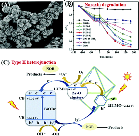 | ||
| Fig. 27 (A) SEM image of BiOBr/NH2-UiO-66(Zr); (B) photocatalytic degradation of Noroxin by different samples under simulated sunlight irradiation; (C) proposed mechanism for photocatalytic degradation of Noroxin by BiOBr/NH2-UiO-66(Zr). Adapted with permission from ref. 196, © 2018 Elsevier Ltd. | ||
In addition to traditional Type II heterojunctions, novel MOF-based Z-scheme heterojunctions were recently reported.165,167 For example, an Ag3PO4/MIL-53(Fe) composite was prepared through a simple in situ precipitation strategy. The as-prepared binary composite displayed enhanced photocatalytic performance for the degradation of multiple antibiotics such as tetracycline (TC), oxytetracycline (OTC), chlortetracycline (CTC) and deoxytetracycline (DCL). As shown in Fig. 28A, the optimized Ag3PO4/MIL-53(Fe) composite (APM-3) with a 1![[thin space (1/6-em)]](https://www.rsc.org/images/entities/char_2009.gif) :
:![[thin space (1/6-em)]](https://www.rsc.org/images/entities/char_2009.gif) 3 mass ratio exhibited the highest activity for TC degradation. More importantly, the binary composite also displayed higher photostability and recyclability than pristine Ag3PO4 (Fig. 28B). After four cyclic runs for TC degradation, the loss of degradation efficiency using APM-3 was ca. 8%. Whereas, the value was ca. 25% using Ag3PO4. The instability of Ag3PO4 during the photocatalytic process was evidenced by the formation of metallic Ag. More obvious XRD signals of Ag (JCPDS card no. 65-2871) were observed in pristine Ag3PO4 relative to APM-3 (Fig. 28C). Interestingly, the formation of tiny metallic Ag may lead to a Z-scheme structure for charge transfer in the Ag3PO4/MIL-53(Fe) composite. As shown in Fig. 28D, the CB/LUMO positions of Ag3PO4 and MIL-53(Fe) matched well with typical Type II heterojunctions. In this mechanism, the electrons in the LUMO of MIL-53(Fe) (−0.41 eV) will flow into the CB of Ag3PO4 (+0.42 eV). Since the CB edge of Ag3PO4 is more positive than the redox potential of O2/O2˙− (−0.33 eV vs. NHE), the formation of O2˙− was not feasible. Similarly, the HOMO position of MIL-53(Fe) (+2.33 eV) was not energetic enough to oxidize surface HO− into HO˙ (EHO−/HO˙ = +2.40 eV vs. NHE). However, strong signals of both HO˙ and O2˙− were detected by electron spin resonance (ESR) spectroscopy. Thus, the Type II heterojunction mechanism was not suitable for Ag3PO4/MIL-53(Fe). Since metallic Ag was detected during the photocatalytic process, a Z-scheme mechanism can well explain the above phenomena. As depicted in Fig. 28E, metallic Ag nanoparticles with an appropriate Fermi level can act as a bridge for electron transfer from the CB of Ag3PO4 to the HOMO of MIL-53(Fe). In this way, both the high reductive ability of MIL-53(Fe) and the oxidative ability of Ag3PO4 can be well maintained, leading to the generation of sufficient active species (HO˙ and O2˙−).
3 mass ratio exhibited the highest activity for TC degradation. More importantly, the binary composite also displayed higher photostability and recyclability than pristine Ag3PO4 (Fig. 28B). After four cyclic runs for TC degradation, the loss of degradation efficiency using APM-3 was ca. 8%. Whereas, the value was ca. 25% using Ag3PO4. The instability of Ag3PO4 during the photocatalytic process was evidenced by the formation of metallic Ag. More obvious XRD signals of Ag (JCPDS card no. 65-2871) were observed in pristine Ag3PO4 relative to APM-3 (Fig. 28C). Interestingly, the formation of tiny metallic Ag may lead to a Z-scheme structure for charge transfer in the Ag3PO4/MIL-53(Fe) composite. As shown in Fig. 28D, the CB/LUMO positions of Ag3PO4 and MIL-53(Fe) matched well with typical Type II heterojunctions. In this mechanism, the electrons in the LUMO of MIL-53(Fe) (−0.41 eV) will flow into the CB of Ag3PO4 (+0.42 eV). Since the CB edge of Ag3PO4 is more positive than the redox potential of O2/O2˙− (−0.33 eV vs. NHE), the formation of O2˙− was not feasible. Similarly, the HOMO position of MIL-53(Fe) (+2.33 eV) was not energetic enough to oxidize surface HO− into HO˙ (EHO−/HO˙ = +2.40 eV vs. NHE). However, strong signals of both HO˙ and O2˙− were detected by electron spin resonance (ESR) spectroscopy. Thus, the Type II heterojunction mechanism was not suitable for Ag3PO4/MIL-53(Fe). Since metallic Ag was detected during the photocatalytic process, a Z-scheme mechanism can well explain the above phenomena. As depicted in Fig. 28E, metallic Ag nanoparticles with an appropriate Fermi level can act as a bridge for electron transfer from the CB of Ag3PO4 to the HOMO of MIL-53(Fe). In this way, both the high reductive ability of MIL-53(Fe) and the oxidative ability of Ag3PO4 can be well maintained, leading to the generation of sufficient active species (HO˙ and O2˙−).
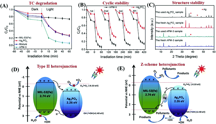 | ||
| Fig. 28 (A) Photocatalytic degradation of TC by different samples under visible light irradiation; (B) cycling stability of Ag3PO4 and Ag3PO4/MIL-53(Fe) composites for photocatalytic degradation of TC; (C) XRD patterns of Ag3PO4 and Ag3PO4/MIL-53(Fe) under different conditions; proposed mechanism for charge separation over Ag3PO4/MIL-53(Fe): (D) Traditional Type II heterojunction and (E) Z-scheme heterojunction. Adapted with permission from ref. 165, © 2018 Elsevier B.V. | ||
Compared with Type I and Type II heterojunctions, there were very few reports of Type III heterojunctions for environmental photocatalysis. In 2016, Wang et al. reported the fabrication of core–shell In2S3@MIL-125(Ti) via a solvothermal method.204 As shown in Fig. 29A, the band positions of In2S3 and MIL-125(Ti) matched well with Type III heterojunctions. Upon visible light irradiation, the photogenerated electrons in the CB of In2S3 will be transferred to the LUMO of MIL-125(Ti), which finally led to the reduction of adsorbed O2. Meanwhile, the corresponding h+ left in the VB of In2S3 will oxidize water into O2. Thus, increased separation of photogenerated charges can be achieved, which finally led to an enhanced degradation of TC (Fig. 29B). However, probably due to the low oxidizing ability of h+ in In2S3, the degradation of TC on optimized In2S3@MIL-125(Ti) slows down with prolonged irradiation time. Besides, the cycling stability for TC degradation exhibited moderate loss (Fig. 29C).
 | ||
| Fig. 29 (A) Proposed mechanism for the charge transfer processes in In2S3@MIL-125(Ti); (B) photocatalytic degradation of TC by different samples; (C) cycling stability of optimized In2S3@MIL-125(Ti) for TC degradation under visible light. Adapted with permission from ref. 204, © 2016 Elsevier. | ||
| MOFs | C3N4 (wt%) | S BET variationa (m2 g−1) | Pollutant | C pollutant (mg L−1) | C catalyst (g L−1) | Time (min) | η variationb (%) | Ref. |
|---|---|---|---|---|---|---|---|---|
| NA: no experimental data available.a SBET variation indicates the surface area of MOFs before and after forming composites.b Removal efficiencies (η) for pollutants are used as received or estimated from the figures in the reference and presented in integer numbers; η variation indicates the performance of MOFs before and after forming composites.c UV-Vis light or sunlight.d Addition of H2O2.e g-C3N4 doped with pyromellitic diimide (PDI).f g-C3N4 nanosheets.g Protonated g-C3N4.h μg g−1.i Addition of PS.j Oxidized g-C3N4. | ||||||||
| Coupled with Zn-MOFs | ||||||||
| ZIF-8(Zn) | 60% | 1318 → 555 | TC | 89 | 0.1 | 60 | 45 → 91c | 217 |
| ZIF-8(Zn) | 97% | NA | TC | 20 | 0.5 | 30 | NA → 74 | 218 |
| RhB | 10 | 0.5 | 75 | NA → 99 | ||||
| MO | 50 | 0.5 | 180 | NA → 86 | ||||
| BUC-21(Zn) | 50% | 1 → 12 | Cr(VI) | 10 | 0.25 | 120 | 13 → 100 | 219 |
| Coupled with Al-MOFs | ||||||||
| MIL-53(Al) | 20% | NA → 44 | RhB | 10 | 0.5 | 75 | NA → 100c | 220 |
| Coupled with Fe-MOFs | ||||||||
| MIL-53(Fe) | 3% | 21 → 19 | Cr(VI) | 10 | 0.4 | 180 | 52 → 100 | 221 |
| NH2-MIL-53(Fe) | 50%e | NA | TCd | 50 | 0.4 | 30 | 82 → 90 | 222 |
| CBZd | 50 | 0.4 | 150 | 52 → 78 | ||||
| BPAd | 50 | 0.4 | 10 | NA → 100 | ||||
| PNPd | 50 | 0.4 | 30 | NA → 100 | ||||
| MIL-88A(Fe) | 90% | 22 → 38 | RhB | 10 | 1.0 | 30 | <5 → 100 | 223 |
| Phenol | 10 | 1.0 | 120 | <5 → 26 | ||||
| TC | 10 | 1.0 | 120 | <5 → 46 | ||||
| MIL-88A(Fe) | NA | 24 → 16 | MB | NA | 1.0 | 120 | 25 → 75 | 224 |
| NH2-MIL-88B(Fe) | 10% | NA | MBd | 30 | 1.0 | 120 | 57 → 100 | 225 |
| MIL-100(Fe) | 1%f | 1225 → 1096 | RhBd | 50 | 0.2 | 240 | 68 → 100 | 226 |
| MIL-100(Fe) | 80% | NA | Cr(VI) | 10 | 0.5 | 80 | 76 → 98c | 227 |
| DSd | 32 | 0.5 | 30 | NA → 100c | ||||
| MIL-100(Fe) | 9%g | 1556 → 1252 | RhB | 10 | 1 | 200 | 36 → 87 | 228 |
| MB | 10 | 1 | 200 | 27 → 82 | ||||
| Pyridine | 560h | 5 | 360 | 53 → 76 | ||||
| MIL-101(Fe) | 2% | NA | BPAi | 10 | 0.5 | 60 | 51 → 100 | 229 |
| NH2-MIL-101(Fe) | NA | NA | Cr(VI) | 10 | 0.5 | 60 | 56 → 100 | 230 |
| Coupled with Zr-MOFs | ||||||||
| UiO-66(Zr) | 50% | 1335 → 1133 | RhB | 10 | 0.4 | 180 | 19 → 93 | 231 |
| UiO-66(Zr) | 50% | 972 → 384 | MB | 10 | 0.25 | 240 | 48 → 100 | 232 |
| PCN-222(Zr) | 99% | NA → 36 | RhB | 20 | 0.1 | 120 | 78 → 98 | 233 |
| Ofloxacin | 20 | 0.1 | 200 | 72 → 96 | ||||
| Coupled with Ti-MOFs | ||||||||
| MIL-125(Ti) | 7% | 1548 → 328 | RhB | 50 | 0.4 | 60 | 15 → 95 | 234 |
| NH2-MIL-125(Ti) | 30% | 1535 → 830 | 4-NP | NA | NA | 240 | 55 → 75 | 235 |
| Coupled with Cu-MOFs | ||||||||
| HKUST-1 | 25%j | 1084 → 392 | DMCP | NA | NA | 1440 | NA | 236 |
| HKUST-1/fiber | 25% | 1084 → 392 | DMCP | NA | NA | 1440 | NA | 237 |
For example, Wang's group reported the facile fabrication of a Type-I heterojunction between a novel Zn-MOF (BUC-21) and g-C3N4 through ball-milling. The as-prepared BUC-21/g-C3N4 composite displayed enhanced photocatalytic performance for Cr(VI) reduction. The radius of the EIS Nyquist plot for the BUC-21/g-C3N4 composite was smaller than either BUC-21 or g-C3N4 (Fig. 30A), indicating the lowest electron transfer impedance. Thus, for the reduction of Cr(VI) under simulated sunlight, BUC-21/g-C3N4 composites with different loading percentages of g-C3N4 displayed significantly enhanced performance (Fig. 30E). After 120 min light irradiation, only 13% and 18% Cr(VI) can be reduced by single BUC-21 and g-C3N4, respectively. Whereas, 100% reduction efficiency can be achieved by the BUC-21/g-C3N4 (B100G100) composite with 50 wt% g-C3N4. In order to further confirm the formation of heterojunctions, a mixture of BUC-21 and g-C3N4 with the same content as optimized BUC-21/g-C3N4 was also tested for Cr(VI) reduction. The value was ca. 52%, which was far less than the composite. For better understanding the interfacial charge transfer mechanism, the band positions of pristine BUC-21 and g-C3N4 were estimated from typical Mott–Schottky measurements. As illustrated in Fig. 30B and C, the flat band potentials were ca. −1.24 V and −1.10 V (vs. Ag/AgCl) for BUC-21 and g-C3N4, corresponding to −1.04 V and −0.90 V (vs. NHE), respectively. Besides, the positive slope of the Mott–Schottky plot indicated an n-type semiconductor. Therefore, the VB position can be calculated from the equation: Eg = EVB − ECB. As shown in Fig. 30D, a Type-I heterojunction can be deduced from the BUC-21/g-C3N4 composite. In addition to UV active BUC-21, Type-I heterojunctions can also be achieved when visible light-active Fe-MOFs were coupled with g-C3N4.224–226,228 For example, MIL-100(Fe) with a tricarboxylate linker was reported to be very stable with a relatively high BET surface area (>1000 m2 g−1).5 The LUMO and HOMO positions of MIL-100(Fe) were estimated to be −0.24 V and 1.73 V (vs. Ag/AgCl) at pH 7, respectively.226 The corresponding CB and VB values were −0.92 V and 1.96 V (vs. Ag/AgCl) for g-C3N4 nanosheets. The MIL-100(Fe)/g-C3N4 composite with a Type I heterojunction exhibited enhanced activity for RhB degradation. After 240 min visible light irradiation, the degradation efficiency increased from 68% on pristine MIL-100(Fe) to 100% on MIL-100(Fe)/g-C3N4.
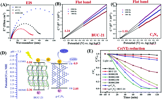 | ||
| Fig. 30 (A) EIS Nyquist plots of different samples; (B) Mott–Schottky plots of BUC-21; (C) Mott–Schottky plots of g-C3N4; (D) proposed mechanism for photogenerated electron transfer by the BUC-21/g-C3N4 heterojunction; (E) photocatalytic reduction of Cr(VI) by different samples. Adapted with permission from ref. 219, © 2018 John Wiley & Sons, Ltd. | ||
In addition to Type-I heterojunctions, UV-active UiO-66(Zr),231,232 MIL-125(Ti)234,235 and visible light-active Fe-MOFs221,224,227,229 were also reported to form Type II heterojunctions with g-C3N4. For example, a g-C3N4/MIL-101(Fe) composite was fabricated for the degradation of bisphenol A (BPA) with persulfate (PS) under visible light. Combined with the results in the Mott–Schottky plots (measuring flat band potential) and UV-Vis DRS spectra (measuring band gap Eg), the CB and VB positions of g-C3N4 were estimated to be −1.1 V and 1.7 V (vs. SCE), respectively. The corresponding LUMO and HOMO values were −0.7 V and 1.9 V (vs. SCE) for MIL-101(Fe), respectively. As shown in Fig. 31A, under visible light irradiation, the photogenerated electrons (e−) will transfer from the CB of g-C3N4 to the LUMO of MIL-101(Fe). Meanwhile, holes (h+) will transfer from the HOMO of MIL-101(Fe) to the VB of g-C3N4. In this way, efficient separation of photogenerated charges can be achieved. Thus, for the visible light-induced degradation of BPA, the g-C3N4/MIL-101(Fe) composite displayed dramatically enhanced performance relative to single MIL-101(Fe) and g-C3N4 (Fig. 31B). The electron transfer process and the reactive centers were further investigated by ESR analysis. As shown in Fig. 31C, an obvious ESR signal can be observed under dark conditions in MIL-101(Fe), which was ascribed to Fe3+ in FeO6. Subsequently, this signal can be totally quenched under visible light irradiation, indicating the disappearance of Fe3+. Due to the presence of extensive Fe–O clusters, which can be directly excited by visible light, the charge transfer from O2− to Fe3+ will lead to the reduction of Fe3+ to Fe2+. Interestingly, after the addition of PS, the ESR signal of Fe3+ can be regenerated, which may be originated from the oxidation of Fe2+ to Fe3+ by PS. Thus, it can be deduced that the active sites for PS activation were metal centers (Fe) in the network of MIL-101(Fe). Besides, stronger signals of DMPO–HO˙ and DMPO–O2˙− were also observed in the g-C3N4/MIL-101(Fe) composite relative to the single ones. The oxidation of H2O/HO− by SO4˙− led to the production of HO˙. Thus, all the active species together boosted the degradation of BPA.
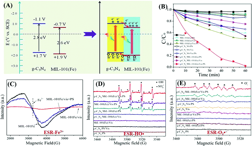 | ||
| Fig. 31 (A) Schematic diagram of the band structure and charge transfer between MIL-101(Fe) and g-C3N4; (B) visible light-induced photocatalytic degradation of BPA under different conditions; (C) ESR spectra of Fe3+ in MIL-101(Fe) under different conditions; ESR signals of (D) DMPO–HO˙ and (E) DMPO–O2˙− in different photocatalytic systems. Adapted with permission from ref. 229, @ 2018 The Royal Society of Chemistry. | ||
A direct Z-scheme heterojunction was also reported in the fabrication of a MIL-88A(Fe)/g-C3N4 composite.223 The introduction of MIL-88A(Fe) can significantly promote the separation of photogenerated charges. For example, lower PL intensity, higher photocurrent response and lower charge transfer resistance were observed on MIL-88A(Fe)/g-C3N4 relative to single components. Therefore, for the photocatalytic degradation of colorful RhB dye and colorless organic pollutants (phenol and tetracycline), the binary composite exhibited excellent performance. Under visible light irradiation, the estimated rate constant for RhB was ca. 0.16 min−1, which was ca. 253 and 5 times that for MIL-88A and g-C3N4, respectively.
3.8 MOF/COF coupling
During the past few decades, great progress has been achieved in the modification of MOFs. Among the various modification strategies, coupling MOFs with other MOFs may possess the merits of individual MOFs and bring in new properties. For example, MOF–MOF hybrid materials with core–shell,238–240 Janus241,242 and hierarchical structures243,244 have been fabricated and applied in many fields, such as catalysis,245 gas detection246 and chemical/biological sensing.247 Since photoactive MOFs possess semiconductor-like behavior, the coupling of different MOFs with matched HOMO–LUMO positions may also lead to the formation of heterojunctions, which subsequently promoted the separation of photogenerated charges as well as photocatalytic performance.248–252 For example, hierarchical MIL-101(Cr)@NH2-MIL-125(Ti) hybrids were developed via an internal extended growth method, which displayed enhanced performance for Cr(VI) reduction under visible light.248 PCN-222/MOF-545 with porphyrin functionality, high porosity and exceptional stability was prepared and applied for the selective degradation of a mustard-gas simulant (2-chloroethyl ethyl sulfide) to nontoxic 2-chloroethyl ethyl sulfoxide.251 As for Fe-MOFs with strong visible light absorption, MIL-100(Fe)/MIL-53(Fe) composites with Type II heterojunctions were fabricated via electrostatic interaction with each other. For the photocatalytic degradation of microcystin-LR (MC-LR), the hybrid material displayed enhanced activity compared to single MIL-53(Fe) and MIL-100(Fe) (Fig. 32A).253 More importantly, the leaching of Fe3+ was significantly suppressed in hybrid MOFs (Fig. 32B). The reason may be ascribed to the electrostatic attraction effect between the two kinds of Fe-MOFs, since the surface of MIL-101 and MIL-53 was negatively and positively charged (at pH 6), respectively. Considering the matched LUMO and HOMO positions, more efficient charge separation can be anticipated (Fig. 32C). Thus, the complete degradation of MC-LR (4.5 mg L−1) can be achieved at a very low dosage (0.02 g L−1) of MIL-100/MIL-53 (Fe).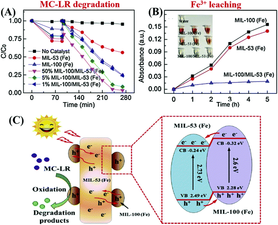 | ||
| Fig. 32 (A) Photocatalytic degradation of MC-LR by different samples under visible light; (B) comparison of Fe(III) ion leaching from MIL-53 (Fe), MIL-100(Fe) and MIL-100(Fe)/MIL-53(Fe), inset: the photo of the aqueous solution during the photocatalytic process; (B) proposed mechanism for charge separation and MC-LR degradation by optimized MIL-100(Fe)/MIL-53(Fe) under visible light. Adapted with permission from ref. 253, © 2019 Elsevier. | ||
Similar to MOFs, metal-free covalent organic frameworks (COFs) are another kind of porous crystalline material, which have recently attracted increasing attention in photocatalysis.254–256 Moreover, MOF–COF hybrid photocatalysts have also been developed.257,258 For example, a core–shell NH2-MIL-68(In)@TPA-COF with high crystallinity and hierarchical porosity was fabricated according to the procedure depicted in Fig. 33A.257 The growth of a sheet-like TPA-COF on the surface of rod-like NH2-MIL-68(In) can be obviously observed (Fig. 33B). Besides, the incorporation of the TPA-COF was further verified by XRD (Fig. 33C) and FT-IR analysis. Since the TPA-COF (2.32 eV) has a narrower band gap than NH2-MIL-68(In) (2.82 eV), the MOF–COF hybridization led to an even smaller band gap (Fig. 33D), corresponding to more efficient utilization of visible light. Besides, due to the introduction of the TPA-COF (1136 m2 g−1), the BET surface area increased from 451 m2 g−1 for NH2-MIL-68(In) to 539 m2 g−1 for the hybrid material. Thus, for the photocatalytic degradation of RhB, the NH2-MIL-68(In)@TPA-COF hybrid displayed enhanced activity.
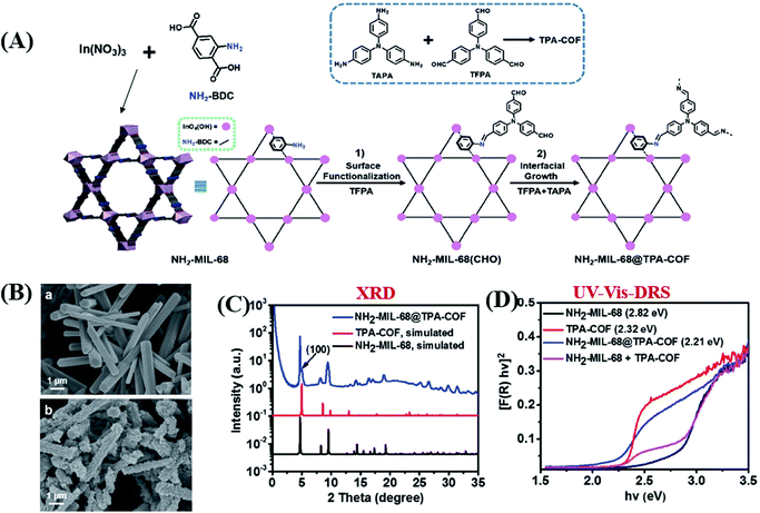 | ||
| Fig. 33 (A) Schematic illustrations for the fabrication of the NH2-MIL-68(In)@TPA-COF; (B) SEM images of (a) NH2-MIL-68(In) and (b) NH2-MIL-68(In)@TPA-COF; (C) XRD patterns and (D) UV-Vis-DRS of different samples. Adapted with permission from ref. 257, © 2017 WILEY-VCH. | ||
Recently, a series of covalently integrated MOF/COF composites with direct Z-scheme heterojunctions were also synthesized via a facile one-pot procedure, such as NH2-MIL-125(Ti)/TTB-TTA, NH2-MIL-53(Al)/TTB-TTA and NH2-UiO-66(Zr)/TTB-TTA.258 Due to well-matched HOMO–LUMO positions and increased separation of charge carriers across the heterojunction interface, significantly enhanced performance can be observed for the photocatalytic degradation of phenol and MO. Besides, the NH2-MIL-125(Ti)/TTB-TTA composite with the highest activity became extremely stable after the incorporation of the TTB-TTA COF. Thus, the hybridization of MOFs with metal free COFs will be very attractive due to the formation of heterojunctions, retention of high surface area and structural stability.
3.9 Hybrid modification strategies
As described above, many single strategies have been reported to modify MOFs for enhanced photocatalytic performance. Each strategy has its own merits and limitations. For better utilization of the merits, proper combination of different strategies may lead to a synergistic effect.As listed in Table 7, many hybrid modification strategies were established and displayed further enhanced photocatalytic performance relative to single strategies. For example, MOFs can be co-modified using MNPs and photoactive semiconductors, MNPs and conducting carbon materials, conducting carbon materials and photoactive semiconductors, etc. Besides, different photoactive semiconductors were also coupled with MOFs constructing multi-heterojunctions for more efficient charge separation.
| Composites |
S
BET![[thin space (1/6-em)]](https://www.rsc.org/images/entities/char_2009.gif) a (m2 g−1) a (m2 g−1) |
Pollutant | C pollutant (mg L−1) | C catalyst (g L−1) | Time (min) |
η
composite![[thin space (1/6-em)]](https://www.rsc.org/images/entities/char_2009.gif) b (%) b (%) |
Ref. |
|---|---|---|---|---|---|---|---|
| NA: no experimental data available; rGO: reduced graphene oxide; GO: graphene oxide; CA: carbon aerogel.a SBET surface area is presented in integer numbers.b Removal efficiencies (η) for pollutants are received or estimated from the figures in the reference and presented in integer numbers.c Addition of H2O2.d UV-Vis light or sunlight.e Under a N2 atmosphere with methanol as a h+ scavenger.f Under the assistance of sonication.g Measured in a continuous flow photocatalytic rotating packed bed for the degradation of dye mixtures. | |||||||
| Co-modification of MOFs using MNPs and photoactive semiconductors | |||||||
| Ag/AgCl@ZIF-8 | 367 | ACT | 1.0 | 0.5 | 90 | 99 | 259 |
| Ag/AgCl/ZIF-8 | 576 | RhB | 10 | 1.0 | 60 | 98 | 260 |
| Ag@AgCl/Ag nanofilm/ZIF-8 | 23 | MB | 10 | 1.0 | 12 | 96 | 261 |
| Pt/ZIF-8/TiO2-NTs | 1100 | Phenol | 52 | NA | 120 | 19 | 262 |
| Ag/AgCl@MIL-53(Fe) | NA | RhB | 10 | 0.4 | 45 | 100 | 263 |
| Cr(VI) | 10 | 0.4 | 240 | 100 | |||
| MIL-53(Fe)/Ag/g-C3N4; | NA | CLQ | 10 | 0.2 | 100 | 95 | 264 |
| Ag/AgCl@MIL-88A(Fe) | 173 | IBP | 10 | 0.4 | 210 | 100 | 265 |
| Ag/AgCl@MIL-101(Cr) | 2016 | RhB | 20 | 1.0 | 18 | 96 | 266 |
| MIL-125(Ti)/Ag/g-C3N4 | 101 | NB | 2050 | 0.83 | 240 | 43e | 267 |
| UiO-66(Zr)/g-C3N4/Ag | 705 | RhB | 20 | 0.4 | 180 | 93 | 268 |
| 2,4-D | 20 | 0.4 | 180 | 84 | |||
| Ag2CrO4/Ag/AgCl-HKUST-1g | NA | AB | 3 | 0.1 | 155 | 98 | 269 |
| OG | 3 | 0.1 | 155 | 90 | |||
| Ag/Ag3PO4/HKUST-1 | 602 | PBS | 55.6 | 1.0 | 80 | 89 | 270 |
| Ag3PO4/AgBr/Ag-HKUST-1g | NA | MB | 15 | 0.4 | 75 | 92 | 271 |
| ER | 15 | 0.4 | 75 | 90 | |||
| A–O | 15 | 0.4 | 75 | 90 | |||
| Co-modification of MOFs using MNPs and conducting carbon materials | |||||||
| Ag/GO/MIL-125(Ti) | 730 | RhB | 50 | 0.4 | 50 | 95 | 272 |
| Pd/GO/MIL-101(Cr) | NA | BC | 25 | 0.25 | 15 | 100 | 273 |
| AF | 25 | 0.25 | 15 | 100 | |||
| Co-modification of MOFs using conducting carbon materials and photoactive semiconductors | |||||||
| BiOBr/GO/MOF-5 | 185 | RhB | NA | NA | 120 | 92 | 274 |
| SnO2@UiO-66(Zr)/rGO | 437 | RhB | 50 | 0.5 | 150 | 96 | 275 |
| Co-modification of MOFs using two different strategies | |||||||
| MIL-100(Fe)@Fe3O4/CA | 390 | TC | 10 | 0.2 | 180 | 85 | 276 |
| Fe–C oxides/MIL-101(Cr) | 1116 | X-3Bc | 100 | 0.1 | 120 | 100d | 277 |
| TiO2@salicylaldehyde-NH2-MIL-101(Cr) | 853 | MBc | 30 | 0.125 | 60 | 86 | 278 |
| H2TCPP⊂(I−)Meim-UiO-66 | 502 | Cr(VI) | 100 | 0.25 | 30 | 100 | 279 |
| 4-PySH@TiO2/PCN-222(Zn) | 1401 | RhBc | 50 | 0.048 | 270 | 98 | 280 |
| 2,4-DNPc | 20 | 0.048 | 270 | 68 | |||
| Co-modification of MOFs using different photoactive semiconductors | |||||||
| BiOI@MIL-88A(Fe)@g-C3N4 | 70 | AB92 | 10 | 0.1 | 180 | 88 | 281 |
| RhB | 10 | 0.1 | 180 | 75 | |||
| Phenol | 10 | 0.1 | 180 | 70 | |||
| Ag3PO4/BiPO4@MIL-88B(Fe)@g-C3N4 | NA | AB92 | 10 | 0.1 | 60 | 85 | 282 |
| Ag3PO4/MIL-101(Cr)/NiFe2O4 | 313 | RhB | 10 | 0.2 | 30 | 95 | 283 |
| CdS/g-C3N4/MIL-125(Ti) | 238 | RhB | NA | NA | 60 | 94 | 284 |
| CdS/NH2-MIL-125@TiO2 | 968 | NO | NA | 4.0 | 5 | 49 | 85 |
| N-K2Ti4O9/g-C3N4/UiO-66(Zr) | 288 | RhB | 10 | 0.2 | 180 | 68d | 285 |
| Cd0.5Zn0.5S@UiO-66(Zr)@g-C3N4 | 147 | MO | 20 | 0.2 | 120 | 82 | 286 |
| BiOI@NH2-UiO-66(Zr)@g-C3N4 | 123 | RhB | 20 | 0.2 | 80 | 95 | 287 |
| TC | 20 | 0.2 | 180 | 79 | |||
| BiPO4/Bi2S3-HKUST-1 | 670 | TB | 25 | 0.25 | 65 | 99 | 288 |
| AO | 25 | 0.25 | 65 | 98 | |||
| Ag3PO4/Bi2S3-HKUST-1f | NA | TB | 25 | 0.25 | 25 | 98 | 289 |
| VS | 25 | 0.25 | 25 | 99 | |||
Among the reported hybrid modification strategies, co-modification of MOFs using MNPs and photoactive semiconductors has been frequently reported. In particular, plasmonic Ag nanoparticles were competitive in comparison with other noble metals (such as Au, Pt and Pd) due to lower price. Until now, various kinds of MOFs (such as ZIF-8, MIL-Fe, MIL-Ti and HKUST) have been co-modified using Ag nanoparticles and semiconductors for environmental photocatalysis. For example, plasmonic Ag/AgCl and spindle-shaped MIL-88A(Fe) were integrated forming an Ag/AgCl@MIL-88A(Fe) (denoted as ACMA) ternary composite via a one-pot solvothermal method.265 As shown in Fig. 34A, Ag/AgCl nanoparticles were uniformly anchored on the surface of spindle-shaped MIL-88A(Fe) microrods. The presence of metallic Ag was further verified by XRD analysis (Fig. 34B) and XPS investigation. The flat-band potential of ACMA was estimated to be −0.75 V via Mott–Schottky plot measurements.290 Thus, the electron transfer from the CB of ACMA to O2 forming reactive O2˙− (0.13 eV) was thermodynamically feasible. For the photocatalytic degradation of ibuprofen (IBP), the Ag/AgCl@MIL-88A(Fe) composite exhibited significantly enhanced performance relative to Ag/AgCl and MIL-88A(Fe). The ternary composite was optimized with an Fe![[thin space (1/6-em)]](https://www.rsc.org/images/entities/char_2009.gif) :
:![[thin space (1/6-em)]](https://www.rsc.org/images/entities/char_2009.gif) Ag molar ratio of 2
Ag molar ratio of 2![[thin space (1/6-em)]](https://www.rsc.org/images/entities/char_2009.gif) :
:![[thin space (1/6-em)]](https://www.rsc.org/images/entities/char_2009.gif) 1 in the initial preparation procedure. Furthermore, trapping experiments were carried out to investigate possible active species involved in the degradation of IBP by optimal ACMA-2. The addition of O2˙− (benzoquinone), h+ (EDTA-2Na) and e− (AgNO3) scavengers all inhibited the degradation dynamics, while the HO˙ scavenger (IPA) had negligible influence. Thus, it can be deduced that O2˙−, h+ and e− play dominant roles in IPA degradation.291 The production of HO˙ (EHO–/HO˙ = 2.38 V vs. NHE)59,290 was thermodynamically infeasible due to weak oxidative ability (Fig. 34C). The degradation products were further detected. As depicted in Fig. 34D, due to the combined effect of O2˙−, h+ and e−, the degradation of IBP started from decarboxylation (by-products 1 and 4) and direct loss of functional groups (by-products 2, 3 and 5). The subsequent ring opening process led to the formation of HCOOH and CH3COOH, which finally were mineralized into CO2 and H2O.
1 in the initial preparation procedure. Furthermore, trapping experiments were carried out to investigate possible active species involved in the degradation of IBP by optimal ACMA-2. The addition of O2˙− (benzoquinone), h+ (EDTA-2Na) and e− (AgNO3) scavengers all inhibited the degradation dynamics, while the HO˙ scavenger (IPA) had negligible influence. Thus, it can be deduced that O2˙−, h+ and e− play dominant roles in IPA degradation.291 The production of HO˙ (EHO–/HO˙ = 2.38 V vs. NHE)59,290 was thermodynamically infeasible due to weak oxidative ability (Fig. 34C). The degradation products were further detected. As depicted in Fig. 34D, due to the combined effect of O2˙−, h+ and e−, the degradation of IBP started from decarboxylation (by-products 1 and 4) and direct loss of functional groups (by-products 2, 3 and 5). The subsequent ring opening process led to the formation of HCOOH and CH3COOH, which finally were mineralized into CO2 and H2O.
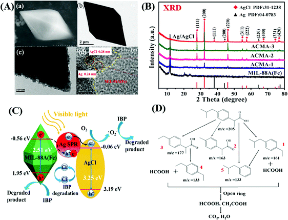 | ||
| Fig. 34 (A) (a) SEM; (b) TEM; (c) and (d) HRTEM images of Ag/AgCl@MIL-88A(Fe); (B) XRD patterns of different samples; (C) proposed mechanism for photocatalytic degradation of IBP by Ag/AgCl@MIL-88A(Fe) under visible light irradiation; (D) proposed degradation pathway of IBP. Adapted with permission from ref. 265, © 2018 Elsevier B.V. | ||
The merits of MNPs and conducting carbon materials can also be combined via co-modification. For example, MIL-125(Ti) was modified with both Ag nanoparticles and rGO. As shown in Fig. 35A–C, bipyramid-like MIL-125(Ti) was enwrapped with rGO and Ag nanoparticles via one-pot self-assembly and a photoreduction method. The BET surface area slightly decreased from 755 m2 g−1 for pristine MIL-125(Ti) to 730 m2 g−1 for Ag/rGO/MIL-125(Ti) with negligible influence on the average pore diameter (2.2 nm vs. 2.3 nm), indicating the maintenance of the microporous structure. Besides, the presence of Ag nanoparticles and rGO can promote the separation of photogenerated charges, which was elucidated by PL spectra. Thus, under visible light irradiation, Ag can be excited to generate e−–h+ pairs due to the plasmonic effect (Fig. 35D). Due to the presence of rGO, the electrons can be more easily transferred to the Ti4+ metal center in MIL-125(Ti). The reduced intermediate Ti3+ will be re-oxidized by O2 generating reactive O2˙−. rGO can also facilitate the interfacial electron transfer from Ag plasma to O2. Meanwhile, HO˙ can be generated by capturing h+. Thus, due to the formation of the above active species, the photocatalytic performance for RhB degradation was accelerated on co-modified MIL-125(Ti) relative to single strategy modified MOFs. The rate constant was in the order of Ag/MIL-125(Ti) (0.052 min−1) < rGO/MIL-125(Ti) (0.0595 min−1) < Ag/rGO/MIL-125(Ti) (0.0644 min−1).
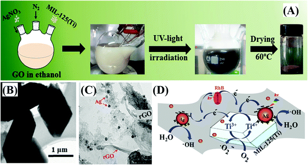 | ||
| Fig. 35 (A) Schematic processes for the preparation of Ag/rGO/MIL-125(Ti); (B) TEM image of MIL-125(Ti); (C) HRTEM image (insert: TEM image) of Ag/rGO/MIL-125(Ti); (D) proposed mechanism for photocatalytic degradation of RhB by the Ag/rGO/MIL-125(Ti) ternary composite. Adapted with permission from ref. 272, © 2016 John Wiley. | ||
Generally, the starting point of most hybrid modification strategies is focused on the formation, separation and transfer of charge carriers, which finally led to enhanced performance for the removal of pollutants. Whereas, the design of an appropriate modification strategy according to the characteristics of target pollutants may be a more promising way. For example, for efficient reduction of Cr(VI) (in the form of anionic Cr2O72− at neutral pH), a visible light-harvesting unit (porphyrin) and a Cr(VI) adsorption site (CH3+) were simultaneous integrated into single MOFs (UiO-66). As illustrated in Fig. 36A, H2TCPP⊂(I−)Meim-UiO-66 (I− as a mobile counter anion) was fabricated via sequential mixed-ligand and ionization routes. The incorporation of the H2TCPP ligand with the porphyrin unit could extend the absorption of UiO-66 from the UV to visible region (Fig. 36B). Meanwhile, the cationic struts could lead to enhanced adsorption of anionic Cr2O72−. Besides, the generation, separation and transfer of charge carriers in UiO-66 were also increased after co-modification. Furthermore, the electron transfer from excited porphyrin to Zr4+ centers can be confirmed from the greatly enhanced ESR signals (g = 2.003) under visible light (Fig. 36C). Time-resolved PL spectra were also used to track the photoexcited carrier in H2TCPP⊂(I−)Meim-UiO-66 (Fig. 36D). After the in situ addition of Cr(VI), the long time constant (τ2) totally disappeared, indicating fast transfer of electrons from H2TCPP to Cr(VI). Thus, due to the above synergistic effect, the photocatalytic reduction of Cr(VI) was significantly boosted (Fig. 36E). After 30 min visible light irradiation, 100 mg L−1 Cr(VI) can be completely removed via adsorption and photoreduction by 0.25 g L−1 H2TCPP⊂(I−)Meim-UiO-66. Herein, the concentration of Cr(VI) was far higher than that of most studies (10 mg L−1). In other words, the rate of Cr(VI) reduction in the present system was 13.3 mgCr(VI) gcatalyst−1 min−1, which was far higher than that in previously reported MOF-based systems. For example, the value was 0.2 mgCr(VI) gcatalyst−1 min−1 for NH2-UiO-66(Zr) and 1.6 mgCr(VI) gcatalyst−1 min−1 NH2-MIL-125(Ti), respectively. Thus, for the removal of environmental pollutants, targeted modification strategies deserve intensive study.
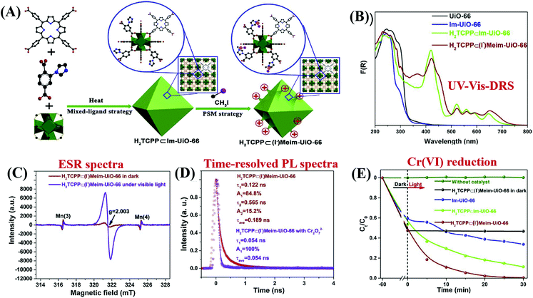 | ||
| Fig. 36 (A) Schematic processes for the preparation of H2TCPP⊂(I−)Meim-UiO-66; (B) UV-vis-DRS of different samples; (C) ESR analyses of H2TCPP⊂(I−)Meim-UiO-66 with Mn as an internal standard; (D) time-resolved PL spectra of H2TCPP⊂(I−)Meim-UiO-66 suspensions with and without the presence of Cr2O72− at an emission wavelength of 650 nm (λex = 400 nm); (E) photocatalytic reduction of Cr(VI) by different samples under visible light irradiation. Adapted with permission from ref. 279, © 2019 Elsevier B.V. | ||
3.10 Carrier loading and magnetic recovery
In addition to high reactivity, good recyclability also plays an important role in further large-scale industrial applications. Since most pristine MOFs are highly dispersive in water and difficult to be separated, it is therefore desirable to enhance the recyclability. Typically, immobilization on an inert carrier or introduction of a magnetic component were proved to be two promising approaches. As listed in Table 8, resin and SBA-15 were applied as supports to immobilize MOFs with enhanced stability and photocatalytic performance.| Composite | S BET variationa (m2 g−1) | Pollutant | C pollutant (mg L−1) | C catalyst (g L−1) | Time (min) | η variation (%) | Ref. |
|---|---|---|---|---|---|---|---|
| NA: no experimental data available.a SBET variation indicates the surface area of MOFs before and after forming composites.b Removal efficiencies (η) for pollutants are used as received or estimated from the figures in the reference and presented in integer numbers; η variation indicates the performance of MOFs before and after forming composites.c mM.d Amberlite IRA-200 resin.e Addition of H2O2.f CA: carbon aerogel. | |||||||
| Immobilization on inert carriers | |||||||
| Resin/MIL-53 (Fe) | NA | SRB | 3.3c | 0.17 | 120 | 24 → 96 | 292 |
| A@FeBTCd | NA | RhB | 35 | 0.4 | 60 | 69 → 99 | 293 |
| HKUST-1/SBA-15 | 197 → 532 | MG | 10 | 0.25 | 80 | NA → 99 | 70 |
| SO | 15 | 0.25 | 80 | NA → 88 | |||
| Combined with magnetic components | |||||||
| Fe3O4@ZIF-67 | 301 | CR | 7 | 0.5 | 30 | NA → 95 | 294 |
| Fe3O4/MIL-53(Fe) | NA | RhBe | 10 | 0.4 | 70 | 99 → 99 | 295 |
| γ-Fe2O3/MIL-53(Fe) | 1835 → 60 | MB | 10 | 0.4 | 240 | 87 → 72 | 296 |
| Fe3O4@MIL-100(Fe) | 1766 → 1245 | DCFe | 60 | 0.1 | 120 | 100 → 91 | 297 |
| Fe3O4@MIL-100(Fe) | 1646 → 213 | MBe | 50 | 0.1 | 120 | 68 → 99 | 298 |
| MIL-100(Fe)@Fe3O4/CAf | 725 → 390 | TC | 10 | 0.2 | 180 | 42 → 85 | 276 |
For example, Huang's group investigated the immobilization of MIL-53(Fe) with anionic resin (Amberlite IRA 200) and cationic resin (Amberlite IRA 900), respectively. The resulting AMIL-53(Fe) and DMIL-53(Fe) showed negligible changes in the UV-Vis DRS spectra and flat band potential measurements, indicating that the optical properties and electronic properties were not influenced after immobilization. Decreased charge transfer resistance can be deduced from the EIS Nyquist plot with a smaller radius of curvature. The different charge characteristic of AMIL-53(Fe) and DMIL-53(Fe) led to prior adsorption and degradation of RhB and SRB, respectively. In particular, a dramatic difference can be observed in the stability of MIL-53. As shown in Fig. 37, the leaching of Fe(III) ions from MIL-53 can be significantly inhibited on AMIL-53(Fe). The reason may be ascribed to the chelation effect between the –SO3− group of Amberlite IRA200 and Fe(III). Accordingly, for the degradation of RhB, AMIL-53 exhibited the highest stability after 5 cyclic runs.
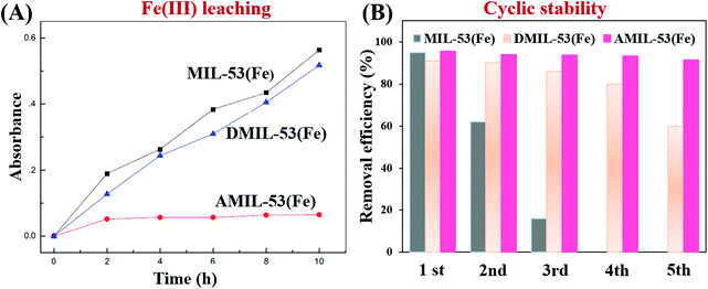 | ||
| Fig. 37 (A) Comparison of Fe(III) ion leaching from MIL-53 (Fe), DMIL-53(Fe) and AMIL-53(Fe) in water under visible light irradiation; (B) comparison of cycling stability for RhB degradation over recycled MIL-53(Fe), DMIL-53(Fe) and AMIL-53(Fe). Adapted with permission from ref. 292, © 2017 Elsevier. | ||
As for preparing magnetically recyclable MOFs, Fe3O4 nanoparticles with good magnetic properties and low toxicity were frequently used to form composites with MOFs. However, due to easy photo-dissolution of Fe3O4, MOFs were designed as shells with Fe3O4 as the core. The as-prepared core–shell structure displayed good stability and recyclability. For example, Zhao's group reported the fabrication of core–shell Fe3O4@MIL-100(Fe) microspheres (Fig. 38A–C).298 Among the as-prepared Fe3O4@MIL-100(Fe) samples, the one with 20 cycles exhibited the highest photocatalytic performance for MB degradation in the presence of H2O2 under visible light. Moreover, the performance of magnetic Fe3O4@MIL-100(Fe) can be well maintained after four cyclic runs with negligible changes in the crystalline structure (Fig. 38D and E). Besides, Fe(III) ion leaching can be greatly inhibited after covering a MOF shell, and a thicker shell is more beneficial (Fig. 38F). For example, the value for Fe(III) ion leaching decreased from 1.96 ppm on pristine MIL-100(Fe) to 0.41 ppm on Fe3O4@MIL-100(Fe) prepared in 40 cycles. Mechanism study further indicated that the photogenerated h+ in the MOF shell can access the Fe3O4 core, leading to efficient separation of e−–h+ pairs. The separated e− can react with H2O2 forming active HO˙ radicals, which finally lead to the degradation of MB dye (Fig. 38G).
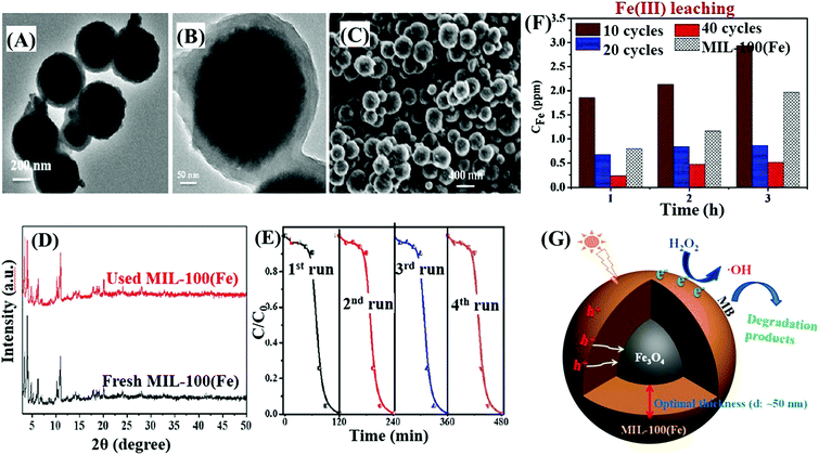 | ||
| Fig. 38 The TEM (A and B) and SEM (C) images of used Fe3O4@MIL-100 with 20 assembly cycles, which had been reacted with H2O2 for 180 min at pH 3.00; (D) comparison of XRD patterns between fresh MIL-100(Fe) and used MIL-100(Fe); (E) cyclic degradation of MB using Fe3O4@MIL-100 with 20 assembly cycles; (F) comparison of Fe(III) ion leaching in water from different Fe3O4@MIL-100(Fe) samples; (G) proposed mechanism for MB degradation. Adapted with permission from ref. 298, © 2015 Wiley-VCH. | ||
4. Conclusions and outlook
In this review, we summarize and illustrate recent progress in MOF-based photocatalysis for environmental remediation. The unparalleled versatility of MOFs allows many strategies to modify and regulate pristine MOFs for enhanced photocatalytic performance under visible light. However, MOF-based environmental photocatalysis is currently at the stage of infancy, which needs to be further developed as amiable and stable technology for low cost practical applications in the future. In general, intensive research work should be carried out to overcome the following challenges and obstacles:(1) Most photo-active MOFs are still at the stage of lab-scale, which cannot be fabricated by one-time high-throughput synthesis. Besides, some preparation methods are complicated and difficult to control. The development of more facile synthetic routes, especially a one-step approach under mild conditions, will be highly desirable for future large-scale applications.
(2) Although there are many reports on water-resistant MOFs, such as UiO-66, MIL-125, MIL-101 and ZIF series, the stability under harsh conditions (strong acidic and alkaline pH) still needs to be improved. Besides, according to metal–ligand bond strengths and the HSAB (hard/soft acid/base) principle,5 the selection of high-valent metal ions (such as Mo6+, W6+, etc.) as metal centers may arouse great interest for fabricating novel stable MOFs.
(3) As for MNP/MOF composites, most of the loaded metal nanoparticles were precious metals (such as Pd, Pt, Au, and Ag). Research on non-precious metals (such as Cu and Bi) deserves more exploration.
(4) In addition to immobilization on an inert carrier and introduction of a magnetic component, the fabrication of MOF films is another attractive way for the recycling of MOFs. However, the utilization of MOF films for environmental photocatalysis was very limited. In particular, the fabrication of MOF films on a conductive substrate needs to be further developed for photoelectrocatalytic degradation of organic pollutants and reduction of heavy metal ions.
(5) Up to now, multi-functional applications of MOFs were limited. There are only sporadic reports on simultaneous photocatalytic oxidation of dyes and reduction of Cr(VI) or H+ (H2 production).47,135,150,299 More efficient multi-functional MOFs are required for the simultaneous and synergistic removal of environmental pollutants and production of energy or valuable products in one system.
(6) For better regulation of MOF photocatalysis, more efforts are needed to intensively explore the degradation processes. For example, the toxicity of degradation intermediates should be evaluated due to incomplete mineralization of organic pollutants under most circumstances.
(7) In addition to the detection of active species (such as HO˙, O2˙− and h+) during photocatalysis, more details associated with the photocatalytic mechanism need in-depth investigation. For example, the adsorption sites of contaminants on the surface/in the channel of MOFs, the interfacial electron transfer mechanism as well as the rate limiting step should be identified. Based on these, the design of appropriate modification strategies will be more scientific and effective.
(8) Finally, there is still an urgent need to develop novel robust MOFs with excellent light harvesting properties, high stability and easy recyclability through the engineering of metallic nodes and organic linkers.
In summary, although there are still many challenges to be solved, in the past two decades of development, researchers from all over the world have made great progress in MOF materials from structural design, controllable modification to functional applications. We believe that with the joint efforts of researchers in many fields, the prospects of MOFs for environmental photocatalysis will be definitely bright.
Conflicts of interest
There are no conflicts to declare.Acknowledgements
The authors are grateful for financial support from the National Natural Science Foundation of China (21876154), the Zhejiang Provincial Natural Science Foundation of China (LR18B070001), the US National Science Foundation (CBET-1706025) and the University of South Florida. The authors also extend their appreciation to the Distinguished Scientist Fellowship Program (DSFP) at King Saud University for partial funding of this work.References
- J. Schneider, M. Matsuoka, M. Takeuchi, J. Zhang, Y. Horiuchi, M. Anpo and D. W. Bahnemann, Chem. Rev., 2014, 114, 9919 CrossRef CAS.
- M. N. Chong, B. Jin, C. W. K. Chow and C. Saint, Water Res., 2010, 44, 2997 CrossRef CAS.
- H. C. Zhou and S. Kitagawa, Chem. Soc. Rev., 2014, 43, 5415 RSC.
- H. Furukawa, N. Ko, Y. B. Go, N. Aratani, S. B. Choi, E. Choi, A. Ö. Yazaydin, R. Q. Snurr, M. O'Keeffe, J. Kim and O. M. Yaghi, Science, 2010, 329, 424 CrossRef CAS PubMed.
- T. Devic and C. Serre, Chem. Soc. Rev., 2014, 43, 6097 RSC.
- E. M. Dias and C. Petit, J. Mater. Chem. A, 2015, 3, 22484 RSC.
- J. Bedia, V. Muelas-Ramos, M. Peñas-Garzón, A. Gómez-Avilés, J. J. Rodríguez and C. Belver, Catalysts, 2019, 9, 52 CrossRef.
- C. C. Wang, X. D. Du, J. Li, X. X. Guo, P. Wang and L. Zhang, Appl. Catal., B, 2016, 193, 198 CrossRef CAS.
- J. D. Xiao, D. Li and H. L. Jiang, Sci. Sin.: Chim., 2018, 48, 1058 Search PubMed.
- J. L. Wang, C. Wang and W. Lin, ACS Catal., 2012, 2, 2630 CrossRef CAS.
- J. He, Y. Zhang, J. He, X. Zeng, X. Hou and Z. Long, Chem. Commun., 2018, 54, 8610 RSC.
- M. A. Nasalevich, M. van der Veen, F. Kapteijn and J. Gascon, CrystEngComm, 2014, 16, 4919 RSC.
- D. Wang, M. Wang and Z. Li, ACS Catal., 2015, 5, 6852 CrossRef CAS.
- C. Wang, X. Liu, N. Keser Demir, J. P. Chen and K. Li, Chem. Soc. Rev., 2016, 45, 5107 RSC.
- P. Li, J. Li, X. Feng, J. Li, Y. Hao, J. Zhang, H. Wang, A. Yin, J. Zhou, X. Ma and B. Wang, Nat. Commun., 2019, 10, 2177 CrossRef.
- Y. Shi, A. F. Yang, C. S. Cao and B. Zhao, Coord. Chem. Rev., 2019, 390, 50 CrossRef CAS.
- X. Ma, L. Wang, Q. Zhang and H. L. Jiang, Angew. Chem., Int. Ed., 2019, 58, 12175 CrossRef CAS.
- C. C. Wang, Y. Q. Zhang, J. Li and P. Wang, J. Mol. Struct., 2015, 1083, 127 CrossRef CAS.
- X. Yu, L. Wang and S. M. Cohen, CrystEngComm, 2017, 19, 4126 RSC.
- S. N. Zhao, G. Wang, D. Poelman and P. Van Der Voort, Molecules, 2018, 23, 2947 CrossRef.
- H. Liu, C. Xu, D. Li and H. L. Jiang, Angew. Chem., 2018, 130, 5477 CrossRef.
- X. Liang, L. Chen, L. Zhang and C. Y. Su, Chin. Sci. Bull., 2018, 63, 248 CrossRef.
- Q. Xia, H. Wang, B. Huang, X. Yuan, J. Zhang, J. Zhang, L. Jiang, T. Xiong and G. Zeng, Small, 2019, 15, 1803088 CrossRef.
- J. D. Xiao and H. L. Jiang, Acc. Chem. Res., 2019, 52, 356 CrossRef CAS.
- L. Jiao, J. Y. R. Seow, W. S. Skinner, Z. U. Wang and H. L. Jiang, Mater. Today, 2019, 27, 43 CrossRef CAS.
- B. Pattengale, S. Yang, J. Ludwig, Z. Huang, X. Zhang and J. Huang, J. Am. Chem. Soc., 2016, 138, 8072 CrossRef CAS PubMed.
- C. C. Wang, J. R. Li, X. L. Lv, Y. Q. Zhang and G. S. Guo, Energy Environ. Sci., 2014, 7, 2831 RSC.
- Y. Li, H. Xu, S. Ouyang and J. Ye, Phys. Chem. Chem. Phys., 2016, 18, 7563 RSC.
- J. Qiu, X. Zhang, Y. Feng, X. Zhang, H. Wang and J. Yao, Appl. Catal., B, 2018, 231, 317 CrossRef CAS.
- J. Bedia, V. Muelas-Ramos, M. Peñas-Garzón, A. Gómez-Avilés, J. J. Rodríguez and C. Belver, Catalysts, 2019, 9, 52 CrossRef.
- D. Wang and Z. Li, Res. Chem. Intermed., 2017, 43, 5169 CrossRef CAS.
- Z. Yan, H. Xi and L. Yuan, Environ. Sci., 2019, 40, 1819 Search PubMed.
- Z. Zhang, X. Li, B. Liu, Q. Zhao and G. Chen, RSC Adv., 2016, 6, 4289 RSC.
- S. R. Thakare and S. M. Ramteke, Catal. Commun., 2017, 102, 21 CrossRef CAS.
- H. Li, M. Eddaoudi, M. O'Keeffe and O. M. Yaghi, Nature, 1999, 402, 276 CrossRef CAS.
- S. Bordiga, C. Lamberti, G. Ricchiardi, L. Regli, F. Bonino, A. Damin, K. P. Lillerud, M. Bjorgen and A. Zecchina, Chem. Commun., 2004, 2300 RSC.
- M. Alvaro, E. Carbonell, B. Ferrer, F. X. Llabres, I. Xamena and H. Garcia, Chem. – Eur. J., 2007, 13, 5106 CrossRef CAS.
- T. Tachikawa, J. R. Choi, M. Fujitsuka and T. Majima, J. Phys. Chem. C, 2008, 112, 14090 CrossRef CAS.
- S. Yuan, L. Feng, K. Wang, J. Pang, M. Bosch, C. Lollar, Y. Sun, J. Qin, X. Yang, P. Zhang, Q. Wang, L. Zou, Y. Zhang, L. Zhang, Y. Fang, J. Li and H. Zhou, Adv. Mater., 2018, 30, 1704303 CrossRef.
- J. H. Cavka, S. Jakobsen, U. Olsbye, N. Guillou, C. Lamberti, S. Bordiga and K. P. Lillerud, J. Am. Chem. Soc., 2008, 130, 13850 CrossRef.
- C. Gomes Silva, I. Luz, F. X. Llabrés i Xamena, A. Corma and H. García, Chem. – Eur. J., 2010, 16, 11133 CrossRef.
- M. Dan-Hardi, C. Serre, T. Frot, L. Rozes, G. Maurin, C. Sanchez and G. Férey, J. Am. Chem. Soc., 2009, 131, 10857 CrossRef CAS.
- L. Shen, R. Liang, M. Luo, F. Jing and L. Wu, Phys. Chem. Chem. Phys., 2015, 17, 117 RSC.
- J. Gascon, M. D. Hernández-Alonso, A. R. Almeida, G. P. M. van Klink, F. Kapteijn and G. Mul, ChemSusChem, 2008, 1, 981 CrossRef CAS.
- J. X. Liu, M. Y. Gao, W. H. Fang, L. Zhang and J. Zhang, Angew. Chem., Int. Ed., 2016, 55, 5160 CrossRef CAS.
- H. Furukawa, K. E. Cordova, M. O'Keeffe and O. M. Yaghi, Science, 2013, 341, 1230444 CrossRef.
- R. Liang, F. Jing, L. Shen, N. Qin and L. Wu, J. Hazard. Mater., 2015, 287, 364 CrossRef CAS.
- Y. K. Seo, J. W. Yoon, J. S. Lee, Y. K. Hwang, C. H. Jun, J. S. Chang, S. Wuttke, P. Bazin, A. Vimont, M. Daturi, S. Bourrelly, P. L. Llewellyn, P. Horcajada, C. Serre and G. Férey, Adv. Mater., 2012, 24, 806 CrossRef CAS.
- P. Horcajada, T. Chalati, C. Serre, B. Gillet, C. Sebrie, T. Baati, J. F. Eubank, D. Heurtaux, P. Clayette, C. Kreuz, J.-S. Chang, Y. K. Hwang, V. Marsaud, P.-N. Bories, L. Cynober, S. Gil, G. Férey, P. Couvreur and R. Gref, Nat. Mater., 2009, 9, 172 CrossRef.
- P. Horcajada, H. Chevreau, D. Heurtaux, F. Benyettou, F. Salles, T. Devic, A. Garcia-Marquez, C. Yu, H. Lavrard, C. L. Dutson, E. Magnier, G. Maurin, E. Elkaïm and C. Serre, Chem. Commun., 2014, 50, 6872 RSC.
- K. Leus, T. Bogaerts, J. De Decker, H. Depauw, K. Hendrickx, H. Vrielinck, V. Van Speybroeck and P. Van Der Voort, Microporous Mesoporous Mater., 2016, 226, 110 CrossRef CAS.
- Y. Fang, J. Wen, G. Zeng, F. Jia, S. Zhang, Z. Peng and H. Zhang, Chem. Eng. J., 2018, 337, 532 CrossRef CAS.
- Y. K. Seo, J. W. Yoon, J. S. Lee, U. H. Lee, Y. K. Hwang, C. H. Jun, P. Horcajada, C. Serre and J. S. Chang, Microporous Mesoporous Mater., 2012, 157, 137 CrossRef CAS.
- D. Wang, F. Jia, H. Wang, F. Chen, Y. Fang, W. Dong, G. Zeng, X. Li, Q. Yang and X. Yuan, J. Colloid Interface Sci., 2018, 519, 273 CrossRef CAS.
- M. C. Das, H. Xu, Z. Wang, G. Srinivas, W. Zhou, Y. F. Yue, V. N. Nesterov, G. Qian and B. Chen, Chem. Commun., 2011, 47, 11715 RSC.
- S. Pu, L. Xu, L. Sun and H. B. Du, Inorg. Chem. Commun., 2015, 52, 50 CrossRef CAS.
- T. L. H. Doan, H. L. Nguyen, H. Q. Pham, N.-N. Pham-Tran, T. N. Le and K. E. Cordova, Chem. – Asian J., 2015, 10, 2660 CrossRef CAS PubMed.
- Y. Gao, S. Li, Y. Li, L. Yao and H. Zhang, Appl. Catal., B, 2017, 202, 165 CrossRef CAS.
- L. Ai, C. Zhang, L. Li and J. Jiang, Appl. Catal., B, 2014, 148–149, 191 CrossRef CAS.
- C. J. N. Liu, Z. Li, W. Huang, B. Gao, F. You and X. Zhang, Mater. Lett., 2019, 237, 92 CrossRef.
- W. Mei, D. Li, H. Xu, J. Zan, L. Sun, Q. Li, B. Zhang, Y. Wang and D. Xia, Chem. Phys. Lett., 2018, 706, 694 CrossRef CAS.
- J. J. Du, Y. P. Yuan, J. X. Sun, F. M. Peng, X. Jiang, L. G. Qiu, A. J. Xie, Y. H. Shen and J. F. Zhu, J. Hazard. Mater., 2011, 190, 945 CrossRef CAS PubMed.
- Y. Gao, G. Yu, K. Liu, S. Deng, B. Wang, J. Huang and W. Wang, Chem. Eng. J., 2017, 330, 157 CrossRef CAS.
- R. Li, Z. Chen, M. Cai, J. Huang, P. Chen and G. Liu, Appl. Surf. Sci., 2018, 457, 726 CrossRef CAS.
- F. Jing, R. Liang, J. Xiong, R. Chen, S. Zhang, Y. Li and L. Wu, Appl. Catal., B, 2017, 206, 9 CrossRef CAS.
- B. Xu, H. Yang, Y. Cai, H. Yang and C. Li, Inorg. Chem. Commun., 2016, 67, 29 CrossRef CAS.
- Y. Li, G. Hou, J. Yang, J. Xie, X. Yuan, H. Yang and M. Wang, RSC Adv., 2016, 6, 16395 RSC.
- W. T. Xu, L. Ma, F. Ke, F. M. Peng, G. S. Xu, Y. H. Shen, J. F. Zhu, L. G. Qiu and Y. P. Yuan, Dalton Trans., 2014, 43, 3792 Search PubMed.
- A. M. G. Kiros, C. A. D. Caiuby, M. Díaz-García, I. Díaz and M. S-Sanchez, Cryst. Growth Des., 2017, 17, 1806 CrossRef.
- S. Mosleh, M. R. Rahimi, M. Ghaedi, K. Dashtian and S. Hajati, RSC Adv., 2016, 6, 17204 RSC.
- M. C. Das, H. Xu, Z. Wang, G. Srinivas, W. Zhou, Y. Yue, V. N. Nesterov, G. Qian and B. Chen, Chem. Commun., 2011, 47, 11715 RSC.
- G. Wang, Q. Sun, Y. Liu, B. Huang, Y. Dai, X. Zhang and X. Qin, Chem. – Eur. J., 2015, 21, 2364 CrossRef CAS PubMed.
- A. N. Meng, L. X. Chaihu, H. H. Chen and Z. Y. Gu, Sci. Rep., 2017, 7, 6297 CrossRef PubMed.
- Y. Fu, D. Sun, Y. Chen, R. Huang, Z. Ding, X. Fu and Z. Li, Angew. Chem., Int. Ed., 2012, 51, 3364 CrossRef CAS PubMed.
- M. A. Nasalevich, M. G. Goesten, T. J. Savenije, F. Kapteijn and J. Gascon, Chem. Commun., 2013, 49, 10575 RSC.
- J. Gao, J. Miao, P. Z. Li, W. Y. Teng, L. Yang, Y. Zhao, B. Liu and Q. Zhang, Chem. Commun., 2014, 50, 3786 RSC.
- C. H. Hendon, D. Tiana, M. Fontecave, C. Sanchez, L. D'Arras, C. Sassoye, L. Rozes, C. Mellot-Draznieks and A. Walsh, J. Am. Chem. Soc., 2013, 135, 10942 CrossRef CAS.
- K. Hendrickx, D. E. P. Vanpoucke, K. Leus, K. Lejaeghere, A. Van Yperen-De Deyne, V. Van Speybroeck, P. Van Der Voort and K. Hemelsoet, Inorg. Chem., 2015, 54, 10701 CrossRef CAS.
- X. P. Wu, L. Gagliardi and D. G. Truhlar, J. Am. Chem. Soc., 2018, 140, 7904 CrossRef CAS.
- A. Dhakshinamoorthy, Z. Li and H. Garcia, Chem. Soc. Rev., 2018, 47, 8134 RSC.
- R. Liang, R. Huang, X. Wang, S. Ying, G. Yan and L. Wu, Appl. Surf. Sci., 2019, 464, 396 CrossRef CAS.
- L. Shi, T. Wang, H. Zhang, K. Chang, X. Meng, H. Liu and J. Ye, Adv. Sci., 2015, 2, 1500006 CrossRef.
- X. D. Du, X. H. Yi, P. Wang, W. W. Zheng, J. G. Deng and C. C. Wang, Chem. Eng. J., 2019, 356, 393 CrossRef CAS.
- S. Hu, M. Liu, K. Y. Li, C. S. Song, G. L. Zhang and X. W. Guo, RSC Adv., 2017, 7, 581 RSC.
- S. Gao, W. Cen, Q. Li, J. Li, Y. Lu, H. Wang and Z. Wu, Appl. Catal., B, 2018, 227, 190 CrossRef CAS.
- H. Wang, X. Yuan, Y. Wu, G. Zeng, X. Chen, L. Leng, Z. Wu, L. Jiang and H. Li, J. Hazard. Mater., 2015, 286, 187 CrossRef CAS.
- R. W. Liang, L. J. Shen, F. F. Jing, W. M. Wu, N. Qin, R. Lin and L. Wu, Appl. Catal., B, 2015, 162, 245 CrossRef CAS.
- J. Wang, J. Wu, L. Lu, H. Xu, M. Trivedi, A. Kumar, J. Liu and M. Zheng, Front. Chem., 2019, 7 DOI:10.3389/fchem.2019.00244.
- L. F. Song, C. H. Jiang, C. L. Jiao, J. Zhang, L. X. Sun, F. Xu, W. S. You, Z. G. Wang and J. J. Zhao, Cryst. Growth Des., 2010, 10, 5020 CrossRef CAS.
- S. Abednatanzi, P. G. Derakhshandeh, H. Depauw, F. X. Coudert, H. Vrielinck, P. V. D. Voort and K. Leus, Chem. Soc. Rev., 2019, 48, 2535 RSC.
- A. Dhakshinamoorthy, A. M. Asiri and H. Garcia, Catal. Sci. Technol., 2016, 6, 5238 RSC.
- M. Kim, J. F. Cahill, H. Fei, K. A. Prather and S. M. Cohen, J. Am. Chem. Soc., 2012, 134, 18082 CrossRef CAS PubMed.
- L. G. Yu, Y. G. Sun and Z. L. Wang, J. Mol. Struct., 2019, 1180, 209 CrossRef CAS.
- Y. Lee, S. Kim, J. K. Kang and S. M. Cohen, Chem. Commun., 2015, 51, 5735 RSC.
- D. Sun, W. Liu, M. Qiu, Y. Zhang and Z. Li, Chem. Commun., 2015, 51, 2056 RSC.
- A. Santiago Portillo, H. G. Baldoví, M. T. García Fernandez, S. Navalón, P. Atienzar, B. Ferrer, M. Alvaro, H. Garcia and Z. Li, J. Phys. Chem. C, 2017, 121, 7015 CrossRef CAS.
- J. Tu, X. Zeng, F. Xu, X. Wu, Y. Tian, X. Hou and Z. Long, Chem. Commun., 2017, 53, 3361 RSC.
- H. Yang, X. W. He, F. Wang, Y. Kang and J. Zhang, J. Mater. Chem., 2012, 22, 21849 RSC.
- S. Das, H. Kim and K. Kim, J. Am. Chem. Soc., 2009, 131, 3814 CrossRef CAS.
- R. Li, X. Ren, H. Ma, X. Feng, Z. Lin, X. Li, C. Hu and B. Wang, J. Mater. Chem. A, 2014, 2, 5724 RSC.
- D. Ao, J. Zhang and H. Liu, J. Photochem. Photobiol., A, 2018, 364, 524 CrossRef CAS.
- T. A. Vu, G. H. Le, C. D. Dao, L. Q. Dang, K. T. Nguyen, P. T. Dang, H. T. K. Tran, Q. T. Duong, T. V. Nguyen and G. D. Lee, RSC Adv., 2014, 4, 41185 RSC.
- J. Li, J. Yang, Y. Y. Liu and J. F. Ma, Chem. – Eur. J., 2015, 21, 4413 CrossRef CAS.
- A. Abbasi, M. Soleimani, M. Najafi and S. Geranmayeh, Inorg. Chim. Acta, 2016, 439, 18 CrossRef CAS.
- J. Cao, Z. H. Yang, W. P. Xiong, Y. Y. Zhou, Y. R. Peng, X. Li, C. Y. Zhou, R. Xu and Y. R. Zhang, Chem. Eng. J., 2018, 353, 126 CrossRef CAS.
- M. Wang, L. Yang, C. Guo, X. Liu, L. He, Y. Song, Q. Zhang, X. Qu, H. Zhang, Z. Zhang and S. Fang, ChemistrySelect, 2018, 3, 3664 CrossRef CAS.
- A. S. Yasin, J. Li, N. Wu and T. Musho, Phys. Chem. Chem. Phys., 2016, 18, 12748 RSC.
- J. Klinowski, F. A. Almeida Paz, P. Silva and J. Rocha, Dalton Trans., 2011, 40, 321 RSC.
- Z. Ni and R. I. Masel, J. Am. Chem. Soc., 2006, 128, 12394 CrossRef CAS.
- J. S. Choi, W. J. Son, J. Kim and W. S. Ahn, Microporous Mesoporous Mater., 2008, 116, 727 CrossRef CAS.
- T. W. Goh, C. Xiao, R. V. Maligal-Ganesh, X. Li and W. Huang, Chem. Eng. Sci., 2015, 124, 45 CrossRef CAS.
- R. Grau-Crespo, A. Aziz, A. W. Collins, R. Crespo-Otero, N. C. Hernández, L. M. Rodriguez-Albelo, A. R. Ruiz-Salvador, S. Calero and S. Hamad, Angew. Chem., Int. Ed., 2016, 55, 16012 CrossRef CAS.
- R. Navarro Amador, M. Carboni and D. Meyer, RSC Adv., 2017, 7, 195 RSC.
- L. Shi, L. Yang, H. Zhang, K. Chang, G. Zhao, T. Kaka and J. Ye, Appl. Catal., B, 2018, 224, 60 CrossRef CAS.
- K. A. Kovalenko, N. V. Ruban, S. A. Adonin, D. V. Korneev, S. B. Erenburg, S. V. Trubina, K. Kvashnina, M. N. Sokolov and V. P. Fedin, New J. Chem., 2017, 41, 2255 RSC.
- H. Li, F. Zhai, D. Gui, X. Wang, C. Wu, D. Zhang, X. Dai, H. Deng, X. Su, J. Diwu, Z. Lin, Z. Chai and S. Wang, Appl. Catal., B, 2019, 254, 47 CrossRef CAS.
- Y. P. Yuan, L. S. Yin, S. W. Cao, G. S. Xu, C. H. Li and C. Xue, Appl. Catal., B, 2015, 168–169, 572 CrossRef CAS.
- E. H. Otal, M. L. Kim, M. E. Calvo, L. Karvonen, I. O. Fabregas, C. A. Sierra and J. P. Hinestroza, Chem. Commun., 2016, 52, 6665 RSC.
- J. Qin, S. Wang and X. Wang, Appl. Catal., B, 2017, 209, 476 CrossRef CAS.
- S. Yang, B. Pattengale, E. L. Kovrigin and J. Huang, ACS Energy Lett., 2017, 2, 75 CrossRef CAS.
- T. Zhou, Y. Du, A. Borgna, J. Hong, Y. Wang, J. Han, W. Zhang and R. Xu, Energy Environ. Sci., 2013, 6, 3229 RSC.
- C. Wang, K. E. deKrafft and W. Lin, J. Am. Chem. Soc., 2012, 134, 7211 CrossRef CAS PubMed.
- S. R. Thakare and S. M. Ramteke, J. Phys. Chem. Solids, 2018, 116, 264 CrossRef CAS.
- Q. Liang, M. Zhang, Z. Zhang, C. Liu, S. Xu and Z. Li, J. Alloys Compd., 2017, 690, 123 CrossRef CAS.
- Q. Li, Z. Fan, L. Zhang, Y. Li, C. Chen, R. Zhao and W. Zhu, J. Solid State Chem., 2019, 269, 465 CrossRef CAS.
- L. H. Zhang, Y. Zhu, B. R. Lei, Y. Li, W. Zhu and Q. Li, Inorg. Chem. Commun., 2018, 94, 27 CrossRef CAS.
- X. Han, X. Yang, G. Liu, Z. Li and L. Shao, Chem. Eng. Res. Des., 2019, 143, 90 CrossRef CAS.
- Q. Yang, Q. Xu and H. L. Jiang, Chem. Soc. Rev., 2017, 46, 4774 RSC.
- T. Zhang, Y. Jin, Y. Shi, M. Li, J. Li and C. Duan, Coord. Chem. Rev., 2019, 380, 201 CrossRef CAS.
- D. N. Jiang, P. Xu, H. Wang, G. M. Zeng, D. L. Huang, M. Chen, C. Lai, C. Zhang, J. Wan and W. J. Xue, Coord. Chem. Rev., 2018, 376, 449 CrossRef CAS.
- X. Fang, Q. Shang, Y. Wang, L. Jiao, T. Yao, Y. Li, Q. Zhang, Y. Luo and H. L. Jiang, Adv. Mater., 2018, 30, 1705112 CrossRef.
- D. Sun and Z. Li, J. Phys. Chem. C, 2016, 120, 19744 CrossRef CAS.
- J. D. Xiao, L. Han, J. Luo, S. H. Yu and H. L. Jiang, Angew. Chem., Int. Ed., 2018, 57, 1103 CrossRef CAS.
- D. Li, S. H. Yu and H. L. Jiang, Adv. Mater., 2018, 30, 1707377 CrossRef.
- L. Shen, W. Wu, R. Liang, R. Lin and L. Wu, Nanoscale, 2013, 5, 9374 RSC.
- S. L. R. Liang, F. Jing, L. Shen, N. Qin and L. Wu, Appl. Catal., B, 2015, 176–177, 240 CrossRef.
- R. Liang, F. Jing, L. Shen, N. Qin and L. Wu, Nano Res., 2015, 8, 3237 CrossRef CAS.
- J. Qiu, L. Yang, M. Li and J. Yao, Mater. Res. Bull., 2019, 112, 297 CrossRef CAS.
- T. Toyao, M. Saito, Y. Horiuchi, K. Mochizuki, M. Iwata, H. Higashimura and M. Matsuoka, Catal. Sci. Technol., 2013, 3, 2092 RSC.
- H. Guo, D. Guo, Z. Zheng, W. Weng and J. Chen, Appl. Organomet. Chem., 2015, 29, 618 CrossRef CAS.
- R. M. Abdelhameed, M. M. Simoes, A. M. Silva and J. Rocha, Chem. – Eur. J., 2015, 21, 11072 CrossRef CAS PubMed.
- W. Zhang, L. Wang and J. Zhang, Res. Chem. Intermed., 2019, 45, 4801 CrossRef CAS.
- Y. Huang, Y. Zhang, X. Chen, D. Wu, Z. Yi and R. Cao, Chem. Commun., 2014, 50, 10115 RSC.
- Y. Zhang and S. J. Park, Chem. Eng. J., 2019, 369, 353 CrossRef CAS.
- R. Liang, S. Luo, F. Jing, L. Shen, N. Qin and L. Wu, Appl. Catal., B, 2015, 176–177, 240 CrossRef CAS.
- J. Zhang, M. Vasei, Y. Sang, H. Liu and J. P. Claverie, ACS Appl. Mater. Interfaces, 2016, 8, 1903 CrossRef CAS.
- J. S. Lee, K. H. You and C. B. Park, Adv. Mater., 2012, 24, 1084 CrossRef CAS.
- M. Han, S. Zhu, S. Lu, Y. Song, T. Feng, S. Tao, J. Liu and B. Yang, Nano Today, 2018, 19, 201 CrossRef CAS.
- Y. Zhang, G. Li, H. Lu, Q. Lv and Z. Sun, RSC Adv., 2014, 4, 7594 RSC.
- R. Liang, L. Shen, F. Jing, N. Qin and L. Wu, ACS Appl. Mater. Interfaces, 2015, 7, 9507 CrossRef CAS.
- C. Yang, X. You, J. Cheng, H. Zheng and Y. Chen, Appl. Catal., B, 2017, 200, 673 CrossRef CAS.
- T. A. Vu, G. H. Le, H. T. Vu, K. T. Nguyen, T. T. T. Quan, Q. K. Nguyen, H. T. K. Tran, P. T. Dang, L. D. Vu and G. D. Lee, Mater. Res. Express, 2017, 4, 035038 CrossRef.
- Y. Wu, H. Luo and H. Wang, RSC Adv., 2014, 4, 40435 RSC.
- X. Li, Z. Le, X. Chen, Z. Li, W. Wang, X. Liu, A. Wu, P. Xu and D. Zhang, Appl. Catal., B, 2018, 236, 501 CrossRef CAS.
- G. W. Q. Wang, X. Liang, X. Dong and X. Zhang, Appl. Surf. Sci., 2019, 467–468, 320 Search PubMed.
- L. Shen, L. Huang, S. Liang, R. Liang, N. Qin and L. Wu, RSC Adv., 2014, 4, 2546 RSC.
- X. Wei, Y. Wang, Y. Huang and C. Fan, J. Alloys Compd., 2019, 802, 467 CrossRef CAS.
- X. X. Xu, H. Y. Yang, Z. Y. Li, X. X. Liu and X. L. Wang, Chem. – Eur. J., 2015, 21, 3821 CrossRef CAS.
- Z. Zhang, T. Zheng, X. Li, J. Xu and H. Zeng, Part. Part. Syst. Charact., 2016, 33, 457 CrossRef.
- X. Wu, J. Zhao, L. Wang, M. Han, M. Zhang, H. Wang, H. Huang, Y. Liu and Z. Kang, Appl. Catal., B, 2017, 206, 501 CrossRef CAS.
- Y. Ma, X. Li, Z. Yang, S. Xu, W. Zhang, Y. Su, N. Hu, W. Lu, J. Feng and Y. Zhang, Langmuir, 2016, 32, 9418 CrossRef CAS.
- R. Miao, S. Zhang, J. Liu and Y. Fang, Chem. Mater., 2017, 29, 5957 CrossRef CAS.
- Q. Wang, G. Wang, X. Liang, X. Dong and X. Zhang, Appl. Surf. Sci., 2019, 467–468, 320 CAS.
- H. Wang, L. Zhang, Z. Chen, J. Hu, S. Li, Z. Wang, J. Liu and X. Wang, Chem. Soc. Rev., 2014, 43, 5234 RSC.
- L. Xie, Z. Yang, W. Xiong, Y. Zhou, J. Cao, Y. Peng, X. Li, C. Zhou, R. Xu and Y. Zhang, Appl. Surf. Sci., 2019, 465, 103 CrossRef CAS.
- Y. Han, C. Bai, L. Zhang, J. Wu, H. Meng, J. Xu, Y. Xu, Z. Liang and X. Zhang, New J. Chem., 2018, 42, 3799 RSC.
- A. A. Oladipo, Process Saf. Environ. Prot., 2018, 116, 413 CrossRef CAS.
- H. Yang, X. Liu, X. Song, T. Yang, Z. Liang and C. Fan, Trans. Nonferrous Met. Soc. China, 2015, 25, 3987 CrossRef CAS.
- R. Chandra, S. Mukhopadhyay and M. Nath, Mater. Lett., 2016, 164, 571 CrossRef CAS.
- Y. Xia, S. K. Shang, X. R. Zeng, J. Zhou and Y. Y. Li, Nanomaterials, 2019, 9, 545 CrossRef CAS.
- Y. Zhang and S. J. Park, Appl. Catal., B, 2019, 240, 92 CrossRef CAS.
- M. Ciprian, P. Xu, S. Chaemchuen, R. Tu, S. Zhuiykov, P. M. Heynderickx and F. Verpoort, Microporous Mesoporous Mater., 2018, 267, 185 CrossRef CAS.
- Y. Si, Y. Li, J. Zou, X. Xiong, X. Zeng and J. Zhou, Materials, 2017, 10, 1161 CrossRef.
- Y. Si, Y. Li, Y. Xia, S. Shang, X. Xiong, X. Zeng and J. Zhou, Crystals, 2018, 8, 432 CrossRef.
- Y. H. Ding, X. L. Zhang, N. Zhang, J. Y. Zhang, R. Zhang, Y. F. Liu and Y. Z. Fang, Dalton Trans., 2018, 47, 684 RSC.
- J. Qiu, X. F. Zhang, X. Zhang, Y. Feng, Y. Li, L. Yang, H. Lu and J. Yao, J. Hazard. Mater., 2018, 349, 234 CrossRef CAS PubMed.
- R. Panda, S. Rahut and J. K. Basu, RSC Adv., 2016, 6, 80981 RSC.
- L. Hu, G. Deng, W. Lu, S. Pang and X. Hu, Appl. Surf. Sci., 2017, 410, 401 CrossRef CAS.
- N. Liu, W. Huang, M. Tang, C. Yin, B. Gao, Z. Li, L. Tang, J. Lei, L. Cui and X. Zhang, Chem. Eng. J., 2019, 359, 254 CrossRef CAS.
- Q. Xia, B. Huang, X. Yuan, H. Wang, Z. Wu, L. Jiang, T. Xiong, J. Zhang, G. Zeng and H. Wang, J. Colloid Interface Sci., 2018, 530, 481 CrossRef CAS.
- R. Yuan, C. Yue, J. Qiu, F. Liu and A. Li, Appl. Catal., B, 2019, 251, 229 CrossRef CAS.
- X. Liu, R. Dang, W. Dong, X. Huang, J. Tang, H. Gao and G. Wang, Appl. Catal., B, 2017, 209, 506 CrossRef CAS.
- X. He, H. Fang, D. J. Gosztola, Z. Jiang, P. Jena and W. N. Wang, ACS Appl. Mater. Interfaces, 2019, 11, 12516 CrossRef CAS.
- J. Huang, H. Song, C. Chen, Y. Yang, N. Xu, X. Ji, C. Li and J. A. You, J. Environ. Chem. Eng., 2017, 5, 2579 CrossRef CAS.
- M. Ahmad, S. Chen, F. Ye, X. Quan, S. Afzal, H. Yu and X. Zhao, Appl. Catal., B, 2019, 245, 428 CrossRef CAS.
- J. Zheng and Z. Jiao, J. Colloid Interface Sci., 2017, 488, 234 CrossRef CAS.
- J. Yang, X. Niu, S. An, W. Chen, J. Wang and W. Liu, RSC Adv., 2017, 7, 2943 RSC.
- A. Soheil, K. Elaheh, A. Moghaddam, M. Reza, S. Laura and J. Christoph, J. Solid State Chem., 2018, 266, 54 CrossRef.
- L. He, Y. Dong, Y. Zheng, Q. Jia, S. Shan and Y. Zhang, J. Hazard. Mater., 2019, 361, 85 CrossRef CAS.
- Y. Xu, Q. Chen, H. Yang, M. Lv, Q. He, X. Liu and F. Wei, Mater. Sci. Semicond. Process., 2015, 36, 115 CrossRef CAS.
- L. Wang and L. Zan, Sci. Rep., 2019, 9, 4860 CrossRef.
- Z. Sha, H. S. O. Chan and J. Wu, J. Hazard. Mater., 2015, 299, 132 CrossRef CAS.
- Z. Sha, J. Sun, H. S. O. Chan, S. Jaenicke and J. Wu, ChemPlusChem, 2015, 80, 1321 CrossRef CAS.
- S. Li, X. Wang, Q. He, Q. Chen, Y. Xu, H. Yang, M. M. Lu, F. Y. Wei and X. T. Liu, Chin. J. Catal., 2016, 37, 367 CrossRef CAS.
- Z. Sha and J. Wu, RSC Adv., 2015, 5, 39592 RSC.
- Z. Yang, X. Tong, J. Feng, S. He, M. Fu, X. Niu, T. Zhang, H. Liang, A. Ding and X. Feng, Chemosphere, 2019, 220, 98 CrossRef CAS.
- R. Zhang, B. Du, Q. Li, Z. Cao, G. Feng and X. Wang, Appl. Surf. Sci., 2019, 466, 956 CrossRef CAS.
- Q. Zhang, J. Yang, M. Xu, J. Chen, Y. Lou, J. Zhou and L. Cheng, J. Chem. Technol. Biotechnol., 2018, 93, 2710 CrossRef CAS.
- C. Cheng, J. Fang, S. Lu, C. Cen, Y. Chen, L. Ren, W. Feng and Z. Fang, J. Chem. Technol. Biotechnol., 2016, 91, 2785 CrossRef CAS.
- Z. Sha, J. Sun, H. S. On Chan, S. Jaenicke and J. Wu, RSC Adv., 2014, 4, 64977 RSC.
- J. Ding, Z. Yang, C. He, X. Tong, Y. Li, X. Niu and H. Zhang, J. Colloid Interface Sci., 2017, 497, 126 CrossRef CAS.
- B. Liu, X. Liu, J. Liu, C. Feng, Z. Li, C. Li, Y. Gong, L. Pan, S. Xu and C. Sun, Appl. Catal., B, 2018, 226, 234 CrossRef CAS.
- Q. Liang, S. Cui, C. Liu, S. Xu, C. Yao and Z. Li, J. Colloid Interface Sci., 2018, 524, 379 CrossRef CAS.
- H. Wang, X. Yuan, Y. Wu, G. Zeng, H. Dong, X. Chen, L. Leng, Z. Wu and L. Peng, Appl. Catal., B, 2016, 186, 19 CrossRef CAS.
- S. R. Zhu, P. F. Liu, M. K. Wu, W. N. Zhao, G. C. Li, K. Tao, F. Y. Yi and L. Han, Dalton Trans., 2016, 45, 17521 RSC.
- L. Han, X. Zhang and D. Wu, J. Mater. Sci.: Mater. Electron., 2019, 30, 3773 CrossRef CAS.
- Q. Hu, J. Di, B. Wang, M. Ji, Y. Chen, J. Xia, H. Li and Y. Zhao, Appl. Surf. Sci., 2019, 466, 525 CrossRef CAS.
- R. M. Abdelhameed, D. M. Tobaldi and M. Karmaoui, J. Photochem. Photobiol., A, 2018, 351, 50 CrossRef CAS.
- N. A. Rodríguez, A. Savateev, M. A. Grela and D. Dontsova, ACS Appl. Mater. Interfaces, 2017, 9, 22941 CrossRef.
- R. Kaur, A. Rana, R. K. Singh, V. A. Chhabra, K. H. Kim and A. Deep, RSC Adv., 2017, 7, 29015 RSC.
- S. Mosleh, M. R. Rahimi, M. Ghaedi and K. Dashtian, RSC Adv., 2016, 6, 61516 RSC.
- S. Mosleh and M. R. Rahimi, Ultrason. Sonochem., 2017, 35, 449 CrossRef CAS.
- H. Ramezanalizadeh and F. Manteghi, J. Photochem. Photobiol., A, 2017, 346, 89 CrossRef CAS.
- H. Ramezanalizadeh and F. Manteghi, J. Cleaner Prod., 2018, 172, 2655 CrossRef CAS.
- Y. Liang, R. Shang, J. Lu, L. Liu, J. Hu and W. Cui, ACS Appl. Mater. Interfaces, 2018, 10, 8758 CrossRef CAS.
- S. R. Zhu, M. K. Wu, W. N. Zhao, P. F. Liu, F. Y. Yi, G. C. Li, K. Tao and L. Han, Cryst. Growth Des., 2017, 17, 2309 CrossRef CAS.
- S. Panneri, M. Thomas, P. Ganguly, B. N. Nair, A. P. Mohamed, K. G. K. Warrier and U. S. Hareesh, Catal. Sci. Technol., 2017, 7, 2118 RSC.
- D. Yuan, J. Ding, J. Zhou, L. Wang, H. Wan, W. L. Dai and G. Guan, J. Alloys Compd., 2018, 762, 98 CrossRef CAS.
- X. H. Yi, F. X. Wang, X. D. Du, P. Wang and C. C. Wang, Appl. Organomet. Chem., 2019, 33, e4621 CrossRef.
- D. Guo, R. Wen, M. Liu, H. Guo, J. Chen and W. Weng, Appl. Organomet. Chem., 2015, 29, 690 CrossRef CAS.
- W. Huang, L. Ning, X. Zhang, M. Wu and L. Tang, Appl. Surf. Sci., 2017, 425, 107 CrossRef CAS.
- Y. F. Y. Li, Z. Cao, N. Li, D. Chen, Q. Xu and J. Lu, Appl. Catal., B, 2019, 250, 150 CrossRef CAS.
- Z. Shao, D. Zhang, C. Su, X. Pu and Y. Geng, Sep. Purif. Technol., 2019, 220, 16 CrossRef CAS.
- S. G. Khasevani and M. R. Gholami, Inorg. Chem. Commun., 2019, 102, 221 CrossRef.
- X. Li, Y. Pi, L. Wu, Q. Xia, J. Wu, Z. Li and J. Xiao, Appl. Catal., B, 2017, 202, 653 CrossRef CAS.
- J. Hong, C. Chen, F. E. Bedoya, G. H. Kelsall, D. O'Hare and C. Petit, Catal. Sci. Technol., 2016, 6, 5042 RSC.
- X. Du, X. Yi, P. Wang, J. Deng and C. C. Wang, Chin. J. Catal., 2019, 40, 70 CrossRef CAS.
- J. Huang, X. B. Zhang, H. Y. Song, C. X. Chen, F. Q. Han and C. C. Wen, Appl. Surf. Sci., 2018, 441, 85 CrossRef CAS.
- Y. Gong, B. Yang, H. Zhang and X. Zhao, J. Mater. Chem. A, 2018, 6, 23703 RSC.
- B. Liu, Y. Wu, X. Han, J. Lv, J. Zhang and H. Shi, J. Mater. Sci.: Mater. Electron., 2018, 29, 17591 CrossRef CAS.
- X. Zhang, Y. Yang, W. Huang, Y. Yang, Y. Wang, C. He, N. Liu, M. Wu and L. Tang, Mater. Res. Bull., 2018, 99, 349 CrossRef CAS.
- Y. Zhang, J. Zhou, Q. Feng, X. Chen and Z. Hu, Chemosphere, 2018, 212, 523 CrossRef CAS.
- H. Jia, D. Ma, S. Zhong, L. Li, L. Li, L. Xu and B. Li, Chem. Eng. J., 2019, 368, 165 CrossRef CAS.
- H. Wang, X. Yuan, Y. Wu, G. Zeng, X. Chen, L. Leng and H. Li, Appl. Catal., B, 2015, 174–175, 445 CrossRef CAS.
- R. Abazari, A. R. Mahjoub and G. Salehi, J. Hazard. Mater., 2019, 365, 921 CrossRef CAS.
- D. A. Giannakoudakis, N. A. Travlou, J. Secor and T. J. Bandosz, Small, 2017, 13, 1601758 CrossRef.
- D. A. Giannakoudakis, Y. Hu, M. Florent and T. J. Bandosz, Nanoscale Horiz., 2017, 2, 356 RSC.
- K. Koh, A. G. Wong-Foy and A. J. Matzger, Chem. Commun., 2009, 6162 RSC.
- Y. Yoo and H. K. Jeong, Cryst. Growth Des., 2010, 10, 1283 CrossRef CAS.
- T. Fukushima, S. Horike, H. Kobayashi, M. Tsujimoto, S. Isoda, M. L. Foo, Y. Kubota, M. Takata and S. Kitagawa, J. Am. Chem. Soc., 2012, 134, 13341 CrossRef CAS.
- S. Furukawa, K. Hirai, K. Nakagawa, Y. Takashima, R. Matsuda, T. Tsuruoka, M. Kondo, R. Haruki, D. Tanaka, H. Sakamoto, S. Shimomura, O. Sakata and S. Kitagawa, Angew. Chem., 2009, 121, 1798 CrossRef.
- P. Á. Szilágyi, M. Lutz, J. Gascon, J. Juan-Alcañiz, J. van Esch, F. Kapteijn, H. Geerlings, B. Dam and R. van de Krol, CrystEngComm, 2013, 15, 6003 RSC.
- T. Y. Luo, C. Liu, X. Y. Gan, P. F. Muldoon, N. A. Diemler, J. E. Millstone and N. L. Rosi, J. Am. Chem. Soc., 2019, 141, 2161 CrossRef CAS PubMed.
- A. Knebel, P. Wulfert-Holzmann, S. Friebe, J. Pavel, I. Strauß, A. Mundstock, F. Steinbach and J. Caro, Chem. – Eur. J., 2018, 24, 5728 CrossRef CAS.
- X. Yang, S. Yuan, L. Zou, H. Drake, Y. Zhang, J. Qin, A. Alsalme and H. C. Zhou, Angew. Chem., Int. Ed., 2018, 57, 3927 CrossRef CAS PubMed.
- T. Li, J. E. Sullivan and N. L. Rosi, J. Am. Chem. Soc., 2013, 135, 9984 CrossRef CAS.
- N. Zhou, F. Su, C. Guo, L. He, Z. Jia, M. Wang, Q. Jia, Z. Zhang and S. Lu, Biosens. Bioelectron., 2019, 123, 51 CrossRef CAS.
- Y. Gu, Y. Wu, L. Li, W. Chen, F. Li and S. Kitagawa, Angew. Chem., Int. Ed., 2017, 56, 15658 CrossRef CAS.
- G. Jia, L. Liu, L. Zhang, D. Zhang, Y. Wang, X. Cui and W. Zheng, Appl. Surf. Sci., 2018, 448, 254 CrossRef CAS.
- L. Liu, L. Zhang, F. Wang, K. Qi, H. Zhang, X. Cui and W. Zheng, Nanoscale, 2019, 11, 7554 RSC.
- Y. Liu, A. J. Howarth, J. T. Hupp and O. K. Farha, Angew. Chem., Int. Ed., 2015, 54, 9001 CrossRef CAS.
- S. Abdpour, E. Kowsari and M. R. A. Moghaddam, J. Solid State Chem., 2018, 262, 172 CrossRef CAS.
- H. L. Tian, T. Araya, R. P. Li, Y. F. Fang and Y. P. Huang, Appl. Catal., B, 2019, 254, 371 CrossRef CAS.
- P. Pachfule, A. Acharjya, J. Roeser, T. Langenhahn, M. Schwarze, R. Schomäcker, A. Thomas and J. Schmidt, J. Am. Chem. Soc., 2018, 140, 1423 CrossRef CAS.
- Y. Zhi, Z. Li, X. Feng, H. Xia, Y. Zhang, Z. Shi, Y. Mu and X. Liu, J. Mater. Chem. A, 2017, 5, 22933 RSC.
- P. F. Wei, M. Z. Qi, Z. P. Wang, S. Y. Ding, W. Yu, Q. Liu, L. K. Wang, H. Z. Wang, W. K. An and W. Wang, J. Am. Chem. Soc., 2018, 140, 4623 CrossRef CAS.
- Y. Peng, M. Zhao, B. Chen, Z. Zhang, Y. Huang, F. Dai, Z. Lai, X. Cui, C. Tan and H. Zhang, Adv. Mater., 2018, 30, 1705454 CrossRef.
- S. J. He, Q. F. Rong, H. Y. Niu and Y. Q. Cai, Appl. Catal., B, 2019, 247, 49 CrossRef CAS.
- G. D. Fan, X. M. Zheng, J. Luo, H. P. Peng, H. Lin, M. C. Bao, L. Hong and J. J. Zhou, Chem. Eng. J., 2018, 351, 782 CrossRef CAS.
- J. X. Liu, R. Li, Y. F. Wang, Y. W. Wang, X. C. Zhang and C. M. Fan, J. Alloys Compd., 2017, 693, 543 CrossRef CAS.
- J. Liu, R. Li, Y. Hu, T. Li, Z. Jia, Y. Wang, Y. Wang, X. Zhang and C. Fan, Appl. Catal., B, 2017, 202, 64 CrossRef CAS.
- T. T. Isimjan, H. Kazemian, S. Rohani and A. K. Ray, J. Mater. Chem., 2010, 20, 10241 RSC.
- Q. Liu, C. Zeng, L. Ai, Z. Hao and J. Jiang, Appl. Catal., B, 2018, 224, 38 CrossRef CAS.
- S. K. Patra, S. Rahut and J. K. Basu, New J. Chem., 2018, 42, 18598 RSC.
- W. Huang, C. Jing, X. Zhang, M. Tang, L. Tang, M. Wu and N. Liu, Chem. Eng. J., 2018, 349, 603 CrossRef CAS.
- S. Gao, T. Feng, C. Feng, N. Shang and C. Wang, J. Colloid Interface Sci., 2016, 466, 284 CrossRef CAS PubMed.
- Z. Yang, X. Xu, X. Liang, C. Lei, Y. Cui, W. Wu, Y. Yang, Z. Zhang and Z. Lei, Appl. Catal., B, 2017, 205, 42 CrossRef CAS.
- S. Feng, R. Wang, S. Feng, Z. Zhang and L. Mao, Res. Chem. Intermed., 2019, 45, 1263 CrossRef CAS.
- S. Jalali, M. R. Rahimi, K. Dashtian, M. Ghaedi and S. Mosleh, Polyhedron, 2019, 166, 217 CrossRef CAS.
- F. A. Sofi, K. Majid and O. Mehraj, J. Alloys Compd., 2018, 737, 798 CrossRef CAS.
- S. Mosleh, M. R. Rahimi, M. Ghaedi, K. Dashtian, S. Hajati and S. Wang, Chem. Eng. Process., 2017, 114, 24 CrossRef CAS.
- X. Yuan, H. Wang, Y. Wu, G. Zeng, X. Chen, L. Leng, Z. Wu and H. Li, Appl. Organomet. Chem., 2016, 30, 289 CrossRef CAS.
- Y. Wu, H. Luo and L. Zhang, Environ. Sci. Pollut. Res., 2015, 22, 17238 CrossRef CAS.
- Y. Chen, J. Li, B. Zhai and Y. Liang, Colloids Surf., A, 2019, 568, 429 CrossRef CAS.
- X. Zhao, X. Liu, Z. Zhang, X. Liu and W. Zhang, RSC Adv., 2016, 6, 92011 RSC.
- H. U. Rasheed, X. M. Lv, S. Y. Zhang, W. Wei, N. Ullah and J. M. Xie, Adv. Powder Technol., 2018, 29, 3305 CrossRef CAS.
- L. Qin, Z. W. Li, Z. H. Xu, X. W. Guo and G. L. Zhang, Appl. Catal., B, 2015, 179, 500 CrossRef CAS.
- X. Y. Li, Y. H. Pi, Q. B. Xia, Z. Li and J. Xiao, Appl. Catal., B, 2016, 191, 192 CrossRef CAS.
- X. S. Wang, C. H. Chen, F. Ichihara, M. Oshikiri, J. Liang, L. Li, Y. Li, H. Song, S. Wang, T. Zhang, Y. B. Huang, R. Cao and J. Ye, Appl. Catal., B, 2019, 253, 323 CrossRef CAS.
- Y. Zhao, Y. Dong, F. Lu, C. Ju, L. Liu, J. Zhang, B. Zhang and Y. Feng, J. Mater. Chem. A, 2017, 5, 15380 RSC.
- S. Gholizadeh Khasevani and M. R. Gholami, Mater. Res. Bull., 2018, 106, 93 CrossRef CAS.
- S. Gholizadeh Khasevani, N. Mohaghegh and M. R. Gholami, New J. Chem., 2017, 41, 10390 RSC.
- T. Zhou, G. Zhang, H. Zhang, H. Yang, P. Ma, X. Li, X. Qiu and G. Liu, Catal. Sci. Technol., 2018, 8, 2402 RSC.
- Y. Chen, B. Y. Zhai, Y. N. Liang, Y. C. Li and J. Li, J. Solid State Chem., 2019, 274, 32 CrossRef CAS.
- F. Wang, Y. T. Zhang, Y. Xu, X. Wang, S. Li, H. Yang, X. Liu and F. Wei, J. Environ. Chem. Eng., 2016, 4, 3364 CrossRef CAS.
- Q. Liang, J. Jin, C. Liu, S. Xu, C. Yao and Z. Li, Inorg. Chem. Front., 2018, 5, 335 RSC.
- L. Qian, S. Cui, J. Jin, C. Liu, S. Xu, C. Yao and Z. Li, Appl. Surf. Sci., 2018, 456, 899 CrossRef.
- S. Mosleh, M. R. Rahimi, M. Ghaedi, K. Dashtian and S. Hajati, RSC Adv., 2016, 6, 63667 RSC.
- S. Mosleh, M. R. Rahimi, M. Ghaedi and K. Dashtian, Ultrason. Sonochem., 2016, 32, 387 CrossRef CAS.
- N. Liu, W. Huang, X. Zhang, L. Tang, L. Wang, Y. Wang and M. Wu, Appl. Catal., B, 2018, 221, 119 CrossRef CAS.
- M. A. Henderson, W. S. Epling, C. H. F. Peden and C. L. Perkins, J. Phys. Chem. B, 2003, 107, 534 CrossRef CAS.
- T. Araya, M. Jia, J. Yang, P. Zhao, K. Cai, W. H. Ma and Y. P. Huang, Appl. Catal., B, 2017, 203, 768 CrossRef CAS.
- T. Araya, C. C. Chen, M. Jia, D. Johnson, R. P. Li and Y. P. Huang, Opt. Mater., 2017, 64, 512 CrossRef CAS.
- W. Guan, X. Gao, G. Ji, Y. Xing, C. Du and Z. Liu, J. Solid State Chem., 2017, 255, 150 CrossRef CAS.
- C. Zhang, L. Ai and J. Jiang, J. Mater. Chem. A, 2015, 3, 3074 RSC.
- X. Feng, H. Chen and F. Jiang, J. Colloid Interface Sci., 2017, 494, 32 CrossRef CAS.
- S. Li, J. Cui, X. Wu, X. Zhang, Q. Hu and X. Hou, J. Hazard. Mater., 2019, 373, 408 CrossRef CAS.
- H. Zhao, L. Qian, H. Lv, Y. Wang and G. Zhao, ChemCatChem, 2015, 7, 4148 CrossRef CAS.
- S. Kampouri, T. N. Nguyen, M. Spodaryk, R. G. Palgrave, A. Züttel, B. Smit and K. C. Stylianou, Adv. Funct. Mater., 2018, 28, 1806368 CrossRef.
| This journal is © the Partner Organisations 2020 |


