
 Open Access Article
 This Open Access Article is licensed under a Creative Commons Attribution-Non Commercial 3.0 Unported Licence
Catalytic conversion of carbon dioxide (CO2) using coal-based nano-carbon materials
Hongchao Luo *a and
Xinjuan Liub
*a and
Xinjuan Liub
aSchool of Chemistry and Materials Engineering, Liupanshui Normal University, 553004, Guizhou Province, China. E-mail: luohongchao@lpssy.edu.cn
bSchool of Environmental and Chemical Engineering, Dalian University, Dalian 116622, Liaoning Province, China
First published on 27th August 2024
Abstract
Carbon dioxide (CO2) is a prominent greenhouse gas and a widely available carbon resource. The chemical conversion of CO2 into high-value chemicals and fuels is a significant approach for mitigating carbon emissions and attaining carbon neutrality. However, enhancing CO2 adsorption and conversion rates remains a primary challenge in CO2 recycling. The development of high-performance catalysts is pivotal for the catalytic conversion of CO2. In this context, coal-based carbon materials, characterized by their extensive specific surface area and adaptable chemical composition, can offer more reactive active sites and have robust CO2 adsorption capabilities. They can function as either standalone catalysts or as components of composite catalysts, making them promising materials for CO2 reduction. The use of affordable and abundant coal as a precursor for carbon materials represents a crucial avenue for achieving clean and efficient coal utilization. This paper reviews the progress of research on coal-based carbon materials and examines their advantages and challenges as catalysts for CO2 reduction.
Introduction
Carbon dioxide (CO2) is a prevalent greenhouse gas and a constituent of the Earth's atmosphere, playing a pivotal role in the global carbon cycle.1 In recent years, the concepts of “carbon neutrality” and “carbon peak” have gained prominence, leading to a growing number of scholarly publications and conferences dedicated to the chemical utilization of CO2. The chemical transformation of CO2 has emerged as a prominent research area within catalysis and energy.Over the past few decades, intensive research has been conducted on thermocatalysis, biomass catalysis, electrochemical catalysis, photochemical catalysis, photothermal catalysis, and photoelectric catalytic conversion of CO2.2–7 As is evident from these catalytic methods, the driving energy is provided by heat, light, and electricity. Among these methods, thermal catalysis is currently the most commonly used in the commercial field because it can increase the kinetic energy of reactants and reduce the activation energy of reactions. However, this method still faces significant challenges, such as limited product selection, high reaction temperature requirements, and energy-intensive side reactions. Biomass catalysis utilizes biological enzymes as catalysts, offering mild reaction conditions and environmental friendliness. Nevertheless, specific environments are required for these reactions, and they exhibit low CO2 conversion efficiency. Photothermal catalysis, a promising CO2 reduction strategy, leverages solar spectrum absorption to stimulate thermochemical and photochemical processes, synergistically promoting catalytic reactions. This approach enables efficient CO2 conversion under mild conditions, showing great potential. However, these methods have drawbacks, such as low CO2 reduction rates (<10%), poor stability of photothermal catalysts, and insufficient understanding of reaction mechanisms and catalyst deactivation, hindering large-scale industrial application.8 Therefore, electrocatalysis, photocatalysis, and photoelectrocatalysis are gaining increasing attention due to their environmentally friendly nature, mild reaction conditions, low cost, and compatibility with renewable energy, and they offer prospects for sustainable low-carbon energy conversion.
However, due to its linear molecular structure with 16 electrons, CO2 possesses both thermodynamic stability and kinetic inertia.9 These chemical properties present significant challenges for achieving efficient and targeted CO2 conversion, thereby serving as the primary hurdle in the CO2 recycling process. Consequently, the design and synthesis of high-performance catalysts are pivotal in advancing CO2 catalytic conversion technology.10
Notably, existing catalysts for CO2 reduction include monatomic catalysts,11 metal catalysts,12 carbon-based catalysts,13 molecular catalysts,14 and metal–organic frameworks.15 Among them, metal catalysts include precious metal catalysts and nonprecious metal catalysts. Commonly utilized noble metal-based catalysts include gold (Au), silver (Ag), platinum (Pt), and palladium (Pd).16–21 These noble metal-based catalysts predominantly engage in the electrocatalytic reduction of CO2 to CO, displaying commendable conductivity and superior CO selectivity.22 However, in initial investigations, the expense of conventional precious metal materials impeded their widespread application, and their modest catalytic activity and reaction rate were insufficient for practical applications. Common nonprecious metals include copper (Cu), zinc (Zn), tin (Sn), bismuth (Bi), and nickel (Ni),23–28 which have been extensively researched for their favorable selectivity and high Faraday efficiency (FE). Nonetheless, nonnoble metal catalysts experience a succession of physical and chemical alterations during prolonged reaction periods, leading to catalyst deactivation. Concurrently, nonprecious metal catalysts remain limited in large-scale production due to cost constraints, curtailing their real-world applicability. Single-atom catalysts (SACs) have emerged as promising platforms for the CO2RR due to their optimal atom utilization, distinct active sites, precisely defined coordination, and distinctive electronic structure.29–31 The tailoring coordination configurations of SACs, including the metal center type, adjacent coordination atoms, and molecular modifications, markedly influence the SAC geometry and electronic structure and thereby regulate the CO2RR reaction pathway and product distribution.32 Within this catalyst, monoatomic metals (M-NC, M = Mn, Fe, Ni, Co, Bi, Zn, In, Sn, Sb, etc.) supported on nitrogen-doped carbon exhibit nearly 100% efficiency in CO or formic acid generation from the CO2RR.33–43 Nevertheless, reducing the single metal atom size to the atomic level often leads to agglomeration during catalyst preparation and utilization, undermining catalyst stability. Addressing the single-atom loading capacity remains an urgent challenge in single-atom catalyst utilization. Currently, three categories of high-efficiency CO2RR molecular catalyst complexes exist: macrocyclic ligand metal catalysts, bipyridine ligand metal catalysts, and phosphine ligand metal catalysts. These complexes, combined with metals such as nickel (Ni), cobalt (Co), and iron (Fe), catalyze carbon dioxide reduction to carbon monoxide or CO and H2 mixtures. In addition to nonprecious metals, costlier metals such as rhenium, rhodium, and iridium often integrate bipyridine ligands and are highly efficient and selective for CO and formate generation.44 Molecular catalysts feature well-defined molecular structures, facilitating molecular-level reaction mechanism elucidation and offering designable molecular structures.45 However, their current density remains insufficient for commercial application demands. Carbon-based materials offer significant advantages in the CO2RR.46 Their precursors mainly include biomass materials (coconut shell, glucose, starch, lignin, etc.), natural graphite, coal, and derivatives, which are characterized by their abundance, affordability, high conductivity, structural stability, environmental friendliness, and renewability.47 Among these materials, coal-based functional carbon materials have made substantial strides in applications related to energy storage, catalysis, composite materials, and environmental protection.48 As an abundant and economical carbon-rich mineral resource, coal comprises fundamental structural units, including condensed aromatic rings and mineral catalysts. These attributes render coal a viable raw material for the synthesis of coal-based functional carbon materials.49 Furthermore, utilizing coal as a precursor for such materials offers an effective approach to realizing the clean utilization of coal resources. This transition holds significant importance in steering coal from its conventional use as a fossil fuel toward applications in new energy materials, nanomaterials, and clean fuels (e.g., coal-to-oil and coal-to-natural gas) as well as specialty chemicals (e.g., coal-to-methanol, olefin, and glycol).50–53 This paper reviews the progress in research on coal-based carbon materials and their applications in the catalytic conversion of CO2, thereby providing guidance for the efficient and environmentally friendly utilization of coal resources.
Research progress on coal-based carbon materials
Coal, in addition to graphite and diamond, ranks as the naturally occurring mineral with the highest carbon content. It is also the most abundant and economically accessible carbon resource. From a chemical standpoint, coal is a highly intricate natural organic macromolecular substance composed of a macromolecular framework that includes aromatic units interconnected or crosslinked by various functional groups, such as aliphatic and ether groups.54 The molecular structure of coal contains C, H, O, N, S, and other elements; N mainly exists in the form of heterocycles, and S mainly exists in the form of heterocycles and thioether bonds. There is a certain small molecular structure in the coal structure, which is either embedded in the aromatic nuclear structure or linked to the aromatic nuclear structure by hydrogen bonding and van der Waals forces.55 The macromolecular structure of the organic part of coal depends on the grade (degree of coalification) and impregnation composition (coal type).56 To date, researchers around the world have proposed more than 100 models of the chemical structure of coal, among which the most famous ones are the Wender model, Given model, Wiser model, Fuchs model, etc., and the structural model diagram is shown in Fig. 1.57 Due to the difficulty of studying coal structure, there is no coherent conclusion and no theoretical or methodological system for constructing a system.58 However, its molecular structure resembles that of carbon materials, featuring a “microcrystalline stone and ink structure” within its constituent composition. Moreover, its aromaticity and graphitization level exhibit a linear relationship with temperature within a specific temperature range.59 These characteristics establish coal as a valuable precursor material for carbon-based materials. | ||
| Fig. 1 Models of the chemical structure of coal: (a) Wender model; (b) given model; (c) Fuchs model; (d) Wiser model.57 | ||
Coal-based carbon materials (CCMs) include a diverse range of materials, including porous carbon, fullerenes, carbon nanotubes, carbon spheres, carbon fibers, graphene, and carbon dots, as illustrated in Fig. 2.48 Various methods are employed for their preparation, such as traditional activated pyrolysis,60 chemical etching methods, template methods,61 supercritical fluid treatment, arc discharge methods, solid-phase methods, and catalytic graphitization–chemical oxidation–plasma-assisted deoxidation technology.62–65 Additionally, microwave irradiation has been reported by several research groups in recent years.66,67 Table 1 provides an overview of different CCMs prepared using diverse coal precursors, methods, catalysts, and temperatures. Depending on these factors, the resulting products exhibit distinct characteristics. Coal-based precursors can be categorized into two main groups: different grades of raw coal, such as anthracite, bituminous coal, and lignite, and various coal derivatives, including coke and coal tar.81
 | ||
| Fig. 2 Different carbon materials derived from coal, highlighting their potential for coal utilization via a molecular chemical engineering strategy.48 | ||
| Precursor | Activator | Temperature (°C) | Method | Product | SBET (m2 g−1) | Ref. |
|---|---|---|---|---|---|---|
| Zhundong coal | FeCl3, CO2 | 900 | Melt-infiltration method | Activated carbon | 1872 | 68 |
| Coal tar pitch | KOH | 800 | Template | Porous carbon | 3305 | 69 |
| Air-dried bituminous coal | KOH | 900 | Conventional heating | Carbon nanotubes | — | 70 |
| Subbituminous coal | — | 150 | Wet-chemical methods | Graphene-like carbon nanosheets | — | 71 |
| Asphaltene | KOH | 800 | Template | Porous carbon nanosheet | 1717 | 72 |
| Ashless coal | FeCl3, MgCl2 | 800 | Coimpregnation | Activated carbon | 2329 | 73 |
| Coal tar pitch | Urea and KOH | 600 | Template | N-doped porous carbon nanosheets | 1181 | 74 |
| Coal | MgO, KOH | — | Activation | Graphitic porous carbon | 1351 | 75 |
| Mongolian raw anthracite | NaOH | — | Activation | Activated carbons | 816–2063 | 76 |
| Anthracite | KOH | 900 | Chemical activation | Porous N-doped carbon | 2814 | 77 |
| Lignite | KOH | 700 | H3PO4 hydrothermal and KOH activation | Porous carbon | 2852 | 78 |
| Anthracite | — | — | Acidic oxidation | GQD | — | 79 |
| Anthracite | — | 900 | Graphitization coupled with liquid oxidation | Porous graphene | 640 | 60 |
| Coal tar pitch | — | — | Situ precipitation | MnO2/PGC composites | 190–229 | 80 |
| Fat coal | — | — | Microwave heating | Coal-based carbon foams | — | 66 |
Sun et al.68 presented a straightforward and scalable method for activating carbon from Zhundong coal using CO2 with melt permeation assistance. The procedure involves introducing a small amount (10–20 wt%) of anhydrous FeCl3 into the coal matrix, resulting in the creation of coal-based activated carbon with an SSA of 1872 m2 g−1 through CO2-assisted physical activation. The resulting MI-AC-2 exhibited a partially hierarchical pore structure and a remarkable specific surface area of 1872 m2 g−1. Fig. 3 shows the technical process, nitrogen adsorption/desorption isotherms for different samples, and corresponding DFT pore size distributions. The research findings demonstrate the dual role of the iron coating, which serves as both a pore template and an activation catalyst during the activation process.
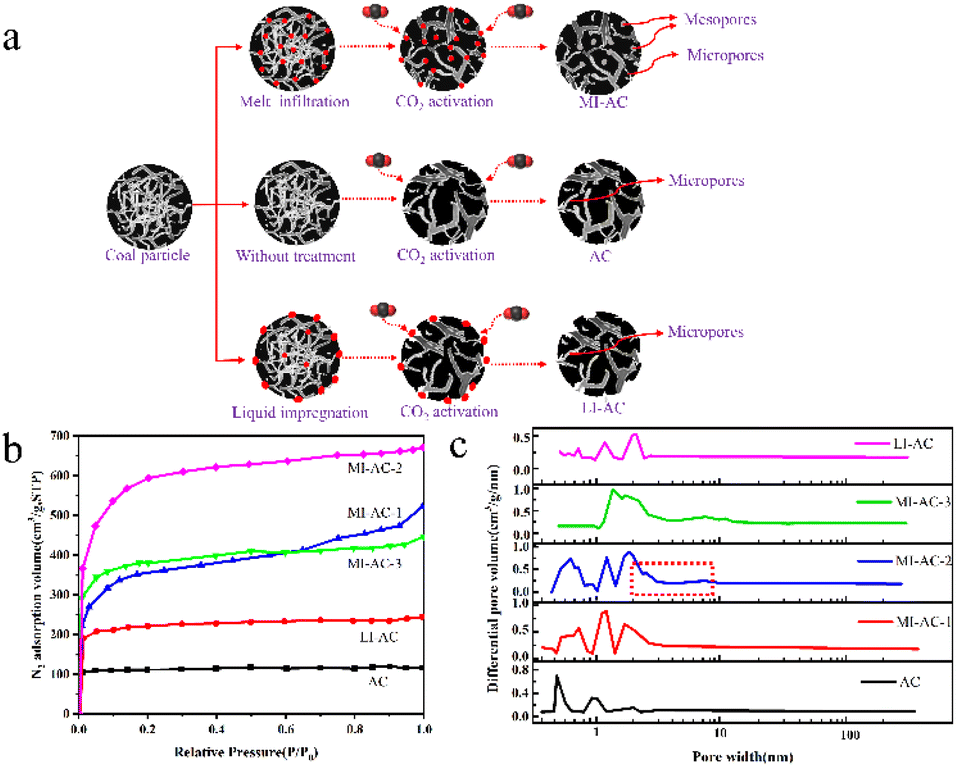 | ||
| Fig. 3 (a) Schematic depiction of coal-based activated carbon preparation via melt permeation-assisted CO2 activation; (b) N2 adsorption/desorption isotherms of the prepared activated carbons; (c) corresponding DFT pore size distributions of the prepared activated carbons.68 | ||
Qin et al.69 achieved the synthesis of interconnected porous carbon with a high SSA of 3305 m2 g−1 and a yield of 29.7 wt% through one-step pyrolysis of a mixture containing coal tar pitch (CTP), microcrystalline cellulose (MCC), and KOH. Moreover, Zhang et al.70 utilized Shanxi air-dried bituminous coal as the feedstock, employing KOH as a catalyst to synthesize carbon nanotubes (CNTs) with wall layers ranging from 18 to 65 and diameters spanning 20 to 155 nm, featuring a well-defined graphite crystal structure. Saikia et al.71 prepared graphene-like carbon nanosheets from low-order subbituminous coal using a wet chemical process.
Islam et al.82 harnessed bituminous coal as their starting material and activated it with KOH, employing a microwave-heat treatment (MW) catalytic method for synthesizing few-layered graphene (FLG, layers = 2–7), which was accomplished in approximately 20 min. Fig. 4 displays the TEM images of FLG doped with 10% Fe, revealing that the defects in the 10% Fe-doped samples are fewer than those in the other catalyst percentages, indicating that the catalyst content influences the structural changes in the FLG composites.
 | ||
| Fig. 4 (a) and (b) Transmission electron microscopy images of 10% FLG samples at different magnifications; (c) and (d) HRTEM images of the FLG film (including an FFT image in the illustration).82 | ||
This research underscores the interdisciplinary nature of coal chemistry and carbon science, emphasizing the potential of coal-based functional carbon materials as precursors for functional carbon material synthesis due to their unique molecular properties. Nonetheless, synthesizing carbon materials from coal with intricate compositions and structures continues to pose a significant challenge.67
Catalytic conversion of CO2
The conversion of CO2 is a prominent subject in addressing energy and environmental issues. Nevertheless, due to the thermodynamic stability and kinetic inertness of CO2, achieving efficient and long-lasting CO2 reduction remains a significant challenge. In the course of this transformation, the selection of catalysts and cocatalysts is of paramount importance.Owing to the inherent attributes of coal-based carbon materials, which stem from the organic macromolecules involved in coal conversion, these materials exhibit distinctive compositions and structures. For example, the large specific surface area structure with adjustable functions, low competition for the hydrogen evolution reaction, good stability, and low cost can not only provide active sites for the reduction of CO2 due to their intrinsic defects but also be used as ideal catalyst materials for the reduction of CO2 by supporting precious metals, nonprecious metals, single-atom catalysts and molecular catalysts, rendering them highly advantageous for catalyzing CO2 conversion.
CO2 photocatalysis
Photocatalytic CO2 conversion closely resembles the photosynthetic process in plants. The process relies on the redox capability of a photocatalyst under sunlight exposure to purify pollutants, synthesize substances, and induce their transformation. A schematic representation of the photocatalytic CO2 reduction process is presented in Fig. 5.84 This principle can be divided into four steps:85 (1) semiconductors are excited by sunlight or visible light, and the generated electrons and holes participate in oxidation–reduction reactions. (2) When light with energy equal to or greater than the band gap is incident upon semiconductor nanoparticles, electrons in the valence band become excited and transition to the conduction band, leaving stable holes in the valence band, thus forming electron–hole pairs. (3) The captured electrons and holes migrate to the surface of the particle. (4) CO2 is reduced by the negative electrons produced into corresponding products, such as CO and CH4. From the reaction mechanism, it can be seen that the photocatalyst reduces CO2 with solar energy or visible light to provide the energy required for the reaction. The reaction is carried out at room temperature and pressure, and there is no secondary pollution problem in the reaction process, which is an environmentally friendly catalytic method. However, it also has certain disadvantages, such as low energy conversion efficiency, low photocatalyst activity, and poor stability. The construction of photocatalysts is important. We can increase the light absorption range of the catalyst by doping it with the elements I, N, S, and C. The deposition of metal materials on the surface of the catalyst prevents the recombination of photogenerated electron–hole pairs, thereby improving its catalytic performance.86 Substrates supported by carbon-based materials with low cost, high conductivity, large surface area, and adjustable surface can also play an important role in the long-term stability of materials.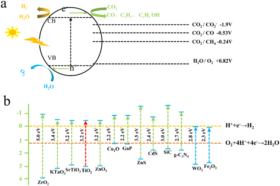 | ||
| Fig. 5 (a) Schematic depiction of the photocatalytic reduction of CO2;83 (b) tunable bandgap semiconductors for photocatalytic CO2 reduction.83 | ||
Photocatalytic CO2 yields various products, including CO, CH4, HCHO, CH3OH, and others,85 and the specific products depend significantly on the chosen photocatalyst.87 However, common photocatalysts are often precious metals, metal oxides, semiconductors, nitrides, sulfides, etc.83 These catalysts exhibit broadband gaps, high costs, low efficiency in utilizing visible light, and low environmental impact.88 In contrast, coal-based carbon materials such as graphene, carbon nanotubes, porous carbon, and other catalysts offer the advantages of low raw material costs, abundant resources, and minimal toxicity, making them a preferred choice for photocatalytic CO2 conversion.
Maimaiti et al.88 employed Xinjiang Wucaiwan coal as the raw material. They first conducted pretreatment with HNO3 and then employed an H2O2 oxidation method to create nanoscale crystalline carbon. Subsequently, they carried out N and S doping of carbon nanoparticles using sulfonyl chloride, chloride, and ethylenediamine passivating methods. This process led to the development of amino coal-based carbon nanoparticles (NH2-CNPs) for photocatalytic CO2 reduction. The findings revealed that the NH2-CNPs were vesicular spherical particles with a particle size of 42.16 ± 7.5 nm and a mesoporous structure suitable for CO2 adsorption, as illustrated in Fig. 6(a)–(c). The products of the photocatalytic reduction of CO2 on the NH2-CNPs included CH3OH, CO, C2H5OH, H2, and CH4. After a 10 h reaction, the total amount of the product was 807.56 μmol g−1 cat−1, and the CH3OH content reached 618.7 μmol g−1 cat−1. The selectivity of CO2 conversion to CH3OH was 76.6%. This outcome can be attributed to the formation of defect structures on the NH2-CNP surface, which enhances the photogeneration of electrons under visible light and the separation of electron–hole pairs.
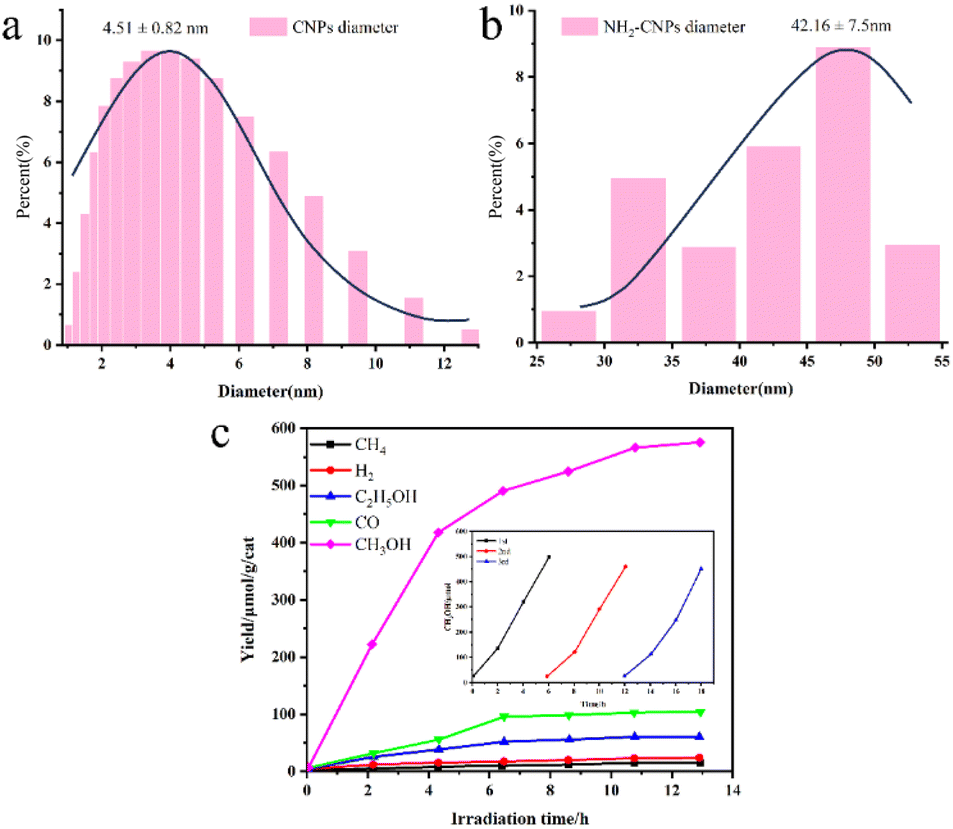 | ||
| Fig. 6 (a) Diameters of the CNPs and (b) NH2-CNPs; (c) photocatalytic reduction products of CO2 on the NH2-CNPs (demonstrating the stability of the NH2-CNPs after 3 repeated uses).88 | ||
Awati et al.89 also produced N,S-codoped amino coal-based carbon points (NH2-CDs) using the aforementioned method. They subsequently coated Cu2O nanoparticles by coordinating and dispersing amino and oxygen-containing functional groups on the surface, resulting in the creation of the Cu2O/NH2-CD composite catalyst (Fig. 7a). The results, as depicted in Fig. 7b and c, reveal that the quantity of HCOOH generated by the photocatalytic Cu2O/NH2-CDs over 6 h was 2582.4 μmol g−1 cat−1, approximately 7.3 times greater than the HCOOH yield of pure Cu2O used as a photocatalyst under identical conditions. This can be ascribed to the presence of NH2-CDs, which enhance both the CO2 adsorption capacity of the composite catalyst and its ability to efficiently separate electron–hole pairs and transfer electrons, thereby significantly enhancing the CO2 reduction performance of the composite photocatalyst.
 | ||
| Fig. 7 (a) Schematic depiction of the synthesis of Cu2O/NH2-CDs; (b) particle distribution of Cu2O/NH2-CDs; (c) influence of the NH2-CDs in the Cu2O/NH2-CDs on the HCOOH and CH3OH yields within 6 h; (d) change in the HCOOH yield over irradiation time with sample CP3 as the catalyst. The inset shows the long-term time curve of recovered sample CP3 for the photocatalysis of CO2 (with solution replacement and photocatalyst recovery every 4 h).89 | ||
Sun et al.90 utilized coal as a carbon source to prepare water-soluble coal-based carbon points with uniform particle sizes and good dispersion via the H2O2 oxidation method. Subsequently, they created silver/cadmium composite nanoparticles through a simple silver mirror reaction. Using these composite particles as photocatalysts, the yield of CH3OH in the photocatalytic reduction of CO2 reached 17.82 μmol g−1 cat−1 after 10 h of illumination, which was nearly three times greater than that of the pure Ag catalyst. This enhancement arises from the strong CO2 adsorption capacity and efficient electron–hole pair separation and electron transfer abilities of the composite catalyst.
Wang et al.91 reported a distinctive Cu2O/RGO composite material, demonstrating that RGO loaded on Cu2O substantially enhances light absorption in the visible light range. This suggests that the Cu2O/RGO composites have a high light utilization rate in photocatalytic reactions. However, it is important to note that the light absorbed by graphene cannot generate photogenerated electron–hole pairs for redox reactions. Consequently, graphene lacks photocatalytic CO2 reduction activity, but properly oxidized graphene exhibits evident photocatalytic CO2 reduction activity, indicating that GO possesses semiconductor properties. Additionally, by adjusting the oxidation degree of GO, the energy band structure can be controlled to meet the requirements of photocatalytic CO2 reduction.92 Based on these studies, the introduction of heteroatoms into coal-based carbon materials can enhance the photocatalytic reduction activity of CO2. Coal-based carbon materials also possess adjustable structural defects, facilitating the adjustment of defect sites and electrical conductivity. All of these factors favor their utilization as photocatalysts for CO2 reduction.
Based on an analysis of the principles underlying photocatalytic reactions, in addition to the band structure of the photocatalyst, the photoexcitation properties, the separation of photogenerated carriers, the adsorption/activation of CO2, the surface active sites of the catalytic reaction, and the adsorption/desorption of intermediates all influence the production of products to varying degrees.93
CO2 electrocatalysis
CO2 electrochemical reduction is a process in which CO2 is reduced at the cathode of an electrolytic cell under an applied voltage, while OH− is oxidized into oxygen at the anode.94 Specifically, CO2 loses 2e−, 4e−, 6e−, 8e− and 12e− or more electrons on the surface of the catalyst, resulting in the formation of different products.95 The electrode potential of the CO2 reduction half-reaction in an aqueous solution under standard conditions (1.0 atm and 298 K) is presented in Table 2.96| Half-reaction | Potential E0 (vs. SHE)/V |
|---|---|
| 2H+ + 2e− → H2 | −0.42 |
| CO2 + e− → CO2− | −1.90 |
| CO2 + 2H+ + 2e− → HCOOH | −0.61 |
| CO2 + 2H+ + 2e− → CO + H2O | −0.53 |
| 2CO2 + 2H+ + 2e− → (COOH)2 | −0.88 |
| CO2 + 4H+ + 4e− → HCHO + H2O | −0.48 |
| CO2 + 6H+ + 6e− → CH3OH + H2O | −0.38 |
| CO2 + 8H+ + 8e− → CH4 + 2H2O | −0.24 |
| 2CO2 + 8H+ + 8e− → CH3COOH + 2H2O | −0.30 |
| 2CO2 + 10H+ + 10e− → CH3CHO + 3H2O | −0.35 |
| 2CO2 + 12H+ + 12e− → C2H4 + 4H2O | −0.34 |
| 2CO2 + 14H+ + 14e− → C2H6 + 4H2O | −0.27 |
| 3CO2 + 16H+ + 16e− → C2H5CHO + 5H2O | −0.32 |
The hydrogen evolution reaction becomes increasingly prominent with increasing external voltage, thereby impeding the reduction of CO2 and resulting in excessive energy consumption.97 Consequently, the identification of a suitable electrocatalyst that can reduce the activation energy required for CO2 reduction and inhibit hydrogen precipitation is crucial for achieving efficient reduction.
Research over the past few decades has demonstrated that precious metals serve as relatively advanced catalysts for the CO2RR, exhibiting high electrocatalytic performance.98–103 However, these catalysts, which are enriched with precious metals, still face certain challenges, including intricate preparation processes, high costs, environmental unfriendliness, and limited stability.104 In recent years, in response to the national drive for clean and efficient coal utilization, coal-based carbon materials have been emerging, primarily due to their high electrocatalytic activity and robust stability, attracting significant attention.
Li et al.104 synthesized folded porous carbon nanosheets from coal tar pitch using an ammonia etching method. The initial overpotential for CO generation was negligibly low at 0.19 V. At an overpotential of −0.49 V, the FE reached 84%. This structure facilitates rapid charge transfer, robust CO2 adsorption, and ample exposure of pyridine-N active sites.
Li et al.105 introduced a straightforward approach to produce N-doped porous carbon (CNPC) by etching coal powder in an NH3 atmosphere, employing bituminous coal as the precursor. When used as a CO2RR catalyst, CNPC achieved an impressive FE of 92% in producing CO at an overpotential of −0.6 V vs. RHE, signifying excellent electrocatalytic performance. This can be attributed to the well-designed porous nanostructure, the abundance of exposed nitrogen defects, and the appropriate ratio of pyridine-N to pyrrole-N.
Liu et al.106 developed a solvent evaporation-induced self-assembly method to fabricate coal-based nitrogen-doped porous carbon using anthracite as the precursor and dicyandiamide as the nitrogen source. During high-temperature processing, the nitrogen atoms derived from dicyandiamide were integrated into the carbon matrix of coal and confined within micropores generated through KOH activation. This spatial confinement effect allowed stable nitrogen atoms in the micropores to effectively convert CO2 into CO.
As demonstrated in Fig. 8a, NPC-800, NPC-900, and NPC-1000, activated by KOH, displayed sharp N2 adsorption under relatively low pressure, implying that NPC-800 was predominantly composed of micropores. However, the hysteresis loops of NPC-800 and NPC-1000 suggested that NPC-1000 possessed some mesoporous pores.107 Notably, NC-900, which was not KOH-activated, did not display apparent N2 adsorption characteristics, underscoring the importance of KOH activation in catalyst preparation. Fig. 8b shows the pore size distribution curves of NPC-800, NPC-900, NPC-1000, and PC-900. An increase in the calcination temperature from 800 °C to 1000 °C led to a reduction in the pore volume, indicating micropore shrinkage, with N atoms enveloped within. Compared with PC-900, NPC-900 exhibited a smaller pore volume, suggesting that the introduced C–N component obstructed a portion of the micropore structure. For NPC-900, the abundant micropores, along with the confined N atoms, provided ample active sites for the CO2RR.108
 | ||
| Fig. 8 (a) Nitrogen adsorption–desorption isotherms of NPC-800, NPC-900, NPC-1000, NC-900, and PC-900; (b) pore width distribution curves of NPC-800, NPC-900, NPC-1000, and PC-900 based on the NLDFT model; (c) CO production rate of NPC-800, NPC-900, NPC-1000, NC-900, and PC-900.106 | ||
These results underscore the significant influence of the N atom distribution on the catalytic activity and product selectivity of NPC during the CO2RR. For the NPC catalyst prepared from NPC-900, an FE of 95% for CO formation was achieved at an overpotential of −0.67 V, with a production rate of 36.1 μmol h−1 cm−2, as depicted in Fig. 8c. Electrocatalytic CO2 reduction includes multiple steps, intermediates, and reaction pathways.109 The aforementioned research attests to the exceptional electrochemical properties of coal-based carbon materials and presents novel avenues for the development of CO2 reduction electrocatalysts.
CO2 photoelectric catalysis
There are several challenges associated with pure photocatalysis reactions, including low solar energy utilization efficiency and poor photogenerated carrier separation efficiency. The integration of electrocatalysis with photocatalysis enhances carrier separation efficiency and facilitates the transfer of multiple electrons and protons to CO2 at a low overpotential, ultimately boosting catalytic reaction efficiency. Photoelectrochemical technology, as illustrated in Fig. 9, combines the merits of photocatalysis and electrocatalysis to enhance the efficiency of catalytic CO2 reduction, offering a novel approach for environmentally friendly CO2 utilization.110 In photoelectric CO2 reduction processes, semiconductor materials typically serve as catalysts.111 However, when the CO2 reduction activity on the semiconductor surface is poor, the photoelectric reaction rate remains sluggish, irrespective of the applied potential level. Therefore, the selection of appropriate electrode materials and the optimization of their properties are crucial for achieving efficient photoelectric reactions.112 | ||
| Fig. 9 Schematic diagram of the photoelectric catalysis of CO2 reduction.110 | ||
In 2015, Hasan et al.113 fabricated RGO-TiO2 composite films through a sol–gel method and electrophoretic deposition. They observed that under light irradiation, the photoelectric activity of RGO-TiO2 surpassed that of pure TiO2, especially at higher pH levels (pH = 11), leading to increased photocurrent density. The high pH value is advantageous for quenching active holes on the photoanode surface, reducing the likelihood of photogenerated electron–hole pair recombination, and consequently decreasing the interfacial charge transfer resistance measured via EIS.
Wang et al.114 reported the use of organic–inorganic lead halide perovskite quantum dots (GO/CH3NH3PbBr3 hybrids) wrapped in GO oxide (GO) to convert CO2 into solar fuel in a nonaqueous medium. Cheng et al.93 developed a highly efficient catalyst (CdS/NCP) with controlled sulfur vacancies and a high pyridine nitrogen content for CO2 reduction to methanol. Studies revealed that CdS/NCP treated at 500 °C exhibited the most substantial S vacancies. A heterojunction formed between CdS with a high S vacancy and NCP with a high pyridyl N content and acted as a cooperative catalyst for CO2 reduction. The CdS/NCP-500 catalyst achieved a 77.3% methanol FE, with a total carbon atom conversion rate of 3052 mmol h−1 cm−2.
Zhang et al.115 employed a simple electrochemical approach to deposit Cu nanoparticle-modified 3D flower-like reduced graphene oxide (f-RGO) (Fig. 10a) on a three-dimensional CF electrode, forming a photocathode (Cu NP/f-RGO/CF). This setup facilitated the synergistic photoelectric reduction of CO2 in PEC cells, which was driven by a compensating voltage applied to the photoanode. In Fig. 10b, the production rates of CO2 reduction products on Cu NP/f-RGO/CF electrodes are compared in PEC cells driven by Pt-TNT photoanodes under PC, EC or PEC conditions (the voltage applied through the cell under EC and PEC conditions is 2 V). During the photoelectric reduction reaction, the f-RGO nanostructure on the CF electrode did not change the type of CO2 reduction products. Nevertheless, it significantly impacts the selectivity of each product: compared to that of the Cu NP/RGO/CF electrode, the selectivity of the C2 product on the Cu NP/f-RGO/CF electrode is markedly enhanced, while the selectivity of the C1 product is reduced. Specifically, the selectivity of acetic acid increased from 26.7% to 31.8%, and the selectivity of ethanol increased from 28.3% to 31.1%. The 3D Cu NP/f-RGO catalyst, in combination with the 3D CF electrode featuring a high specific surface area, not only facilitates robust reactant adsorption and efficient charge transport but also promotes the further conversion of C1 products into higher-order products.
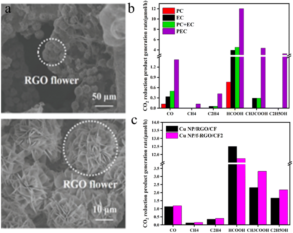 | ||
| Fig. 10 (a) SEM images of the Cu NP/f-RGO/CF electrode (at different resolutions); (b) CO2 reduction product generation rates on Cu NP/f-RGO/CF electrodes in a Pt-TNT photoanode-driven PEC cell under PC, EC, or PEC conditions. The voltage applied through the cell was 2 V under EC and PEC conditions; (c) CO2 reduction product generation rates on the Cu NP/f-RGO/CF and Cu NP/RGO/CF cathodes in a Pt-TNT photoanode-driven PEC cell.115 | ||
Fig. 10c shows the distribution of CO2 reduction products at the Cu NP/f-RGO/CF and Cu NP/RGO/CF cathodes at an optimized potential of 2 V.
It can be seen from Fig. 10c that the CO2 reduction liquid products of the Cu NP/f-RGO/CF and Cu NP/RGO/CF cathodes have significant yields of formic acid, acetic acid, and ethanol, while the gas products of carbon monoxide, methane, and ethylene have low yields.
The analysis above underscores that carbon materials hold promise as catalysts for CO2 photoelectric conversion. Although there are limited studies on coal-based carbon materials (CCMs) as cocatalysts for CO2 reduction, their morphology and structural advantages highlight the potential of CCMs as catalysts for CO2 photoelectric reduction.
Conclusion
To date, most CO2 reduction methods are still in the laboratory stage and have not been commercialized on a large scale. First, how can CO2 be obtained? Most of the CO2 in the air comes from coal combustion and chemical waste gas, and approximately 2386 kg of carbon dioxide will be produced after the combustion of one ton of standard coal. As a chemical product, pure CO2 itself can be used for fire extinguishing, food processing, and refrigerant preparation, which has great economic value, and the cost of using it as a CO2 raw material is too high. Therefore, technologies that can selectively convert low concentrations of CO2 have great economic potential. Second, the molecular stability of carbon dioxide is too good, transformation is difficult, the cost is high, and commercialization is difficult. The design of high-efficiency and high-selectivity catalysts can solve this problem to a certain extent, especially the preparation of metal-free carbon materials with high temperature stability, large specific surface area, excellent conductivity, environmental friendliness and chemical resistance to acids and alkalis with cheap coal as precursors, so that they can be used as catalysts or catalyst carriers alone, which not only reduces the reaction cost but also improves the CO2 conversion efficiency. Nonetheless, research on utilizing carbon materials derived from coal as catalysts for CO2 reduction is limited, with most applications focused on supercapacitors. This underlines the untapped potential of CCMs as catalysts for CO2 reduction.Photocatalysis, electrocatalysis, and photoelectric catalysis are effective approaches for CO2 reduction and transformation. Among these methods, photocatalysis has several advantages: the use of renewable energy sources—solar energy—as an external energy supply and mild reaction conditions at normal temperature and pressure. Photocatalytic CO2 reduction does not cause secondary pollution and is environmentally friendly. However, pure photocatalytic reactions face challenges, such as limited solar energy utilization efficiency, low photocarrier separation efficiency, and subpar selectivity of target products. Electrocatalytic technology uses an external voltage to drive CO2 reduction, providing the required electrons for the reaction and enhancing the selectivity of the target product. Furthermore, the electrolyte can be recycled. However, CO2 is inherently inert, and the electrocatalytic reduction potential for CO2 is similar to that of the hydrogen evolution reaction (HER), which results in low reaction efficiency. The HER inevitably occurs during the CO2RR process, further hindering efficiency. Compared with traditional photocatalysis, photoelectric catalysis uses the synergistic effect of light and electricity to facilitate directional electron–hole transfer, promote the separation of electron–hole pairs, and improve the reduction efficiency of CO2. In addition to that, it is relatively low cost and environmentally friendly. Photoelectric catalysis CO2 reduction also has the disadvantages of low efficiency due to the low light absorption rate, low charge separation and transport efficiency, and unstable nature of the catalyst.
Therefore, the key lies in designing catalysts with high catalytic activity, abundant reactive sites, and robust electron transport capabilities to boost the rate of CO2 reduction. Using the unique characteristics of coal-based carbon materials to design efficient coal-based CO2 reduction catalysts represents a primary approach to enhancing the efficient utilization of coal. More breakthrough technologies are necessary for the promising technology of converting inexpensive coal into high-performance catalysts for CO2 reduction.
Data availability
Data sharing is not applicable to this article as no new data were created or analyzed in this study.Author contributions
Hongchao Luo: conceptualization, supervision, project administration, funding acquisition. Xinjuan Liu: data curation, writing – original draft, writing – review & editing, visualization.86,89Conflicts of interest
There are no conflicts to declare.Acknowledgements
This work is financially supported by Liupanshui Normal University Scientific Research and Cultivation Projects (LPSSYLPY202212), Liupanshui Normal University High-level Talent Research Start-up Fund (LPSSYKJJ201602), Guizhou Provincial Key Laboratory of Coal Clean Utilization (qiankehepingtairencai [2020]2001).Notes and references
- K. Zickfeld, D. Azevedo, S. Mathesius and H. D. Matthews, Nat. Clim. Change, 2021, 11, 613 CrossRef CAS.
- Y. W. Wang, D. He, H. Y. Chen and D. W. Wang, J. Photochem. Photobiol., C, 2019, 40, 117–149 CrossRef.
- N. Han, P. Ding, L. He, Y. Li and Y. Li, Adv. Energy Mater., 2020, 10, 1902338 CrossRef CAS.
- Z. Xie, Y. Xu, M. Xie, X. Chen, J. H. Lee, E. Stavitski, S. Kattel and J. G. Chen, Nat. Commun., 2020, 11, 1887 CrossRef CAS PubMed.
- Y. Zhao, J. Liu, M.-L. Han, G.-P. Yang, L.-F. Ma and Y.-Y. Wang, Rare Met., 2021, 40, 499–504 CrossRef CAS.
- K. Sun, N. Rui, Z. Zhang, Z. Sun, Q. Ge and C.-J. Liu, Green Chem., 2020, 22, 5059–5066 RSC.
- H. Terholsen, H. D. Huerta-Zerón, C. Möller, H. Junge, M. Beller and U. T. Bornscheuer, Angew. Chem., 2024, 136, e202319313 CrossRef.
- M. Sun, B. Zhao, F. Chen, C. Liu, S. Lu, Y. Yu and B. Zhang, Chem. Eng. J., 2021, 408, 127280 CrossRef CAS.
- Y. O. Wang, E. Q. Chen and J. W. Tang, ACS Catal., 2022, 12, 7300–7316 CrossRef CAS PubMed.
- W. P. Kong and J. Liu, RSC Adv., 2019, 9, 4925–4931 RSC.
- S. Liu, H. B. Yang, S. F. Hung, J. Ding, W. Z. Cai, L. H. Liu, J. J. Gao, X. N. Li, X. Y. Ren, Z. C. Kuang, Y. Q. Huang, T. Zhang and B. Liu, Angew. Chem., Int. Ed., 2020, 59, 798–803 CrossRef CAS.
- Y. X. Wang, L. Cao, N. J. Libretto, X. Li, C. Y. Li, Y. D. Wan, C. N. He, J. Lee, J. Gregg, H. Zong, D. Su, J. T. Miller, T. Mueller and C. Wang, J. Am. Chem. Soc., 2019, 141, 16635–16642 CrossRef CAS.
- K. Gong, F. Du, Z. Xia, M. Durstock and L. J. s. Dai, Science, 2009, 323, 760–764 CrossRef CAS PubMed.
- Y. S. Wu, Z. Jiang, X. Lu, Y. Y. Liang and H. L. Wang, Nature, 2019, 575, 639 CrossRef CAS PubMed.
- Y. Chen, D. Wang, X. Deng and Z. J. C. S. Li, Catal. Sci. Technol., 2017, 7, 4893–4904 RSC.
- S. Awasthi, K. Awasthi and A. K. Ghosh, Fuel, 2015, 147, 35–42 CrossRef CAS.
- W. Zhou, J.-K. Guo, S. Shen, J. Pan, J. Tang, L. Chen, C.-T. Au and S. F. Yin, Acta Phys.-Chim. Sin., 2020, 36(10), 3866 Search PubMed.
- J. J. Wang, X. P. Li, B. F. Cui, Z. Zhang, X. F. Hu, J. Ding, Y. D. Deng, X. P. Han and W. B. Hu, Rare Met., 2021, 40, 3019–3037 CrossRef CAS.
- W. Xie, S. Zhang, Y. Ni, G. Shi, J. Li, X. Fu, X. Chen, M. Yuan and M. Wang, Adv. Energy Sustainability Res., 2021, 2, 2100037 CrossRef CAS.
- Q. Chen, P. Tsiakaras and P. Shen, Catalysts, 2022, 12, 1348 CrossRef CAS.
- K. Jiang, X. Y. Ma, S. Back, J. Zhao, F. Jiang, X. Qin, J. Zhang and W. B. Cai, CCS Chem., 2021, 3, 241–251 CrossRef CAS.
- J. Xie, X. Zhao, M. Wu, Q. Li, Y. Wang and J. Yao, Angew. Chem., 2018, 130, 9788–9792 CrossRef.
- Y. Wang, J. Liu and G. Zheng, Adv. Mater., 2021, 33, 2005798 CrossRef CAS.
- Y. Yan, L. Ke, Y. Ding, Y. Zhang, K. Rui, H. Lin and J. Zhu, Mater. Chem. Front., 2021, 5, 2668–2683 RSC.
- J. Kim, H. Kim, G. H. Han and S. H. Ahn, Int. J. Energy Res., 2021, 45, 7987–7997 CrossRef CAS.
- F. Cheng, X. Zhang, K. Mu, X. Ma, M. Jiao, Z. Wang, P. Limpachanangkul, B. Chalermsinsuwan, Y. Gao and Y. Li, Energy Technol., 2021, 9, 2000799 CrossRef CAS.
- Y.-H. Wang, W.-J. Jiang, W. Yao, Z.-L. Liu, Z. Liu, Y. Yang and L. Z. Gao, Energy Technol., 2021, 40, 2327–2353 CAS.
- W. Zheng, C. Guo, J. Yang, F. He, B. Yang, Z. Li, L. Lei, J. Xiao, G. Wu and Y. Hou, Carbon, 2019, 150, 52–59 CrossRef CAS.
- Y. Zhu, J. Sokolowski, X. Song, Y. He, Y. Mei and G. Wu, Adv. Energy Mater., 2020, 10, 1902844 CrossRef CAS.
- H. Fei, J. Dong, D. Chen, T. Hu, X. Duan, I. Shakir, Y. Huang and X. Duan, Chem. Soc. Rev., 2019, 48, 5207–5241 RSC.
- S. Ji, Y. Qu, T. Wang, Y. Chen, G. Wang, X. Li, J. Dong, Q. Chen, W. Zhang and Z. Zhang, Angew. Chem., Int. Ed., 2020, 59, 10651–10657 CrossRef CAS PubMed.
- B. Zhang, J. Zhang, F. Zhang, L. Zheng, G. Mo, B. Han and G. Yang, Adv. Funct. Mater., 2020, 30, 1906194 CrossRef CAS.
- B. Zhang, J. Zhang, J. Shi, D. Tan, L. Liu, F. Zhang, C. Lu, Z. Su, X. Tan and X. Cheng, Nat. Commun., 2019, 10, 2980 CrossRef PubMed.
- W. Ren, X. Tan, W. Yang, C. Jia, S. Xu, K. Wang, S. C. Smith and C. Zhao, Angew. Chem., Int. Ed., 2019, 58, 6972–6976 CrossRef CAS.
- N. Mohd Adli, W. Shan, S. Hwang, W. Samarakoon, S. Karakalos, Y. Li, D. A. Cullen, D. Su, Z. Feng and G. Wang, Angew. Chem., 2021, 133, 1035–1045 CrossRef.
- J. Yang, Z. Qiu, C. Zhao, W. Wei, W. Chen, Z. Li, Y. Qu, J. Dong, J. Luo and Z. Li, Angew. Chem., Int. Ed., 2018, 57, 14095–14100 CrossRef CAS.
- L. Zhou, Z. Qu and L. Fu, J. Environ. Chem. Eng., 2023, 11, 109427 CrossRef CAS.
- H. Xu, S. Shen, C. Lv, H. Zheng, Y. Zhang, C. Ma, W. Qiao, L. Ling and J. Wang, Appl. Surf. Sci., 2024, 648, 159066 CrossRef CAS.
- S. Li, Y. Kang, C. Mo, Y. Peng, H. Ma and J. Peng, Int. J. Mol. Sci., 2022, 23, 14485 CrossRef CAS PubMed.
- M. Zhang, C. Wang, Y. Wang, S. Li, X. Zhang and Y. Liu, Nano Res., 2023, 16, 2142–2151 CrossRef CAS.
- X. Song, W. Guo, X. Ma, L. Xu, X. Tan, L. Wu, S. Jia, T. Wu, J. Ma and F. Zhang, Green Chem., 2022, 24, 1488–1493 RSC.
- Y. Yang, Y. X. Pan, X. Tu and C. Liu, Nano Energy, 2022, 101, 107613 CrossRef CAS.
- S. Ma, K. Wu, S. Fan, Y. Li, Q. Xie, J. Ma and L. Yang, Sep. Purif. Technol., 2024, 339, 126520 CrossRef CAS.
- D. Grammatico, A. J. Bagnall, L. Riccardi, M. Fontecave, B. L. Su and L. Billon, Angew. Chem., 2022, 134, e202206399 CrossRef.
- Z. W. Yang, J. M. Chen, L. Q. Qiu, W. J. Xie and L. N. He, Angew. Chem., Int. Ed., 2022, 61, e202205301 CrossRef CAS PubMed.
- T. Ma, Q. Fan, H. Tao, Z. Han, M. Jia, Y. Gao, W. Ma and Z. Sun, Nanotechnology, 2017, 28, 472001 CrossRef PubMed.
- S. Jin, Z. Hao, K. Zhang, Z. Yan and J. Chen, Angew. Chem., 2021, 133, 20795–20816 CrossRef.
- H. Q. Li, X. J. He, T. T. Wu, B. Y. Jin, L. Yang and J. S. Qiu, Fuel Process. Technol., 2022, 230, 18 CrossRef.
- T. Qiu, PhD thesis, China University of Mining & Technology, 2019.
- S. Y. Park and Y. N. Liang, Fuel, 2016, 166, 258–267 CrossRef CAS.
- S. S. Bukhari, J. Behin, H. Kazemian and S. Rohani, Fuel, 2015, 140, 250–266 CrossRef CAS.
- Z. Zhang, C. M. Liu, W. Liu, Y. Cui, X. Du, D. Xu, H. Guo and Y. L. Deng, Appl. Energy, 2017, 200, 226–236 CrossRef CAS.
- Q. Lyu and Z. Chai, Bull. Chin. Acad. Sci., 2022, 37, 541–548 Search PubMed.
- S. P. Sasikala, L. Henry, G. Yesilbag Tonga, K. Huang, R. Das, B. Giroire, S. Marre, V. M. Rotello, A. Penicaud and P. Poulin, ACS Nano, 2016, 10, 5293–5303 CrossRef CAS PubMed.
- S. Wei, G. C. Yan, Z. Q. Zhang, S. M. Liu and Y. F. Zhang, J. China Coal Soc., 2018, 555–562 Search PubMed.
- I. V. Matlala, O. M. Moroeng, S. Kalaitzidis and N. Wagner, Int. J. Coal Geol., 2024, 104531 CrossRef CAS.
- F. Wang, G. Y. Li, Y. Y. Li and Y. H. Lian. J. C. C. Technology, 2016, vol. 22 Search PubMed.
- Z. H. Qin, Int. J. Min. Sci. Technol., 2018, 28, 541–559 CrossRef.
- H. H. Zeng, B. L. Xing, Y. J. Cao, B. Xu, L. Hou, H. Guo, S. Cheng, G. X. Huang, C. X. Zhang and Q. Sun, Int. J. Min. Sci. Technol., 2022, 32, 1397–1406 CrossRef CAS.
- Y. Zhao, Q. Shi, Z. L. Li, X. L. Li, X. L. Wan and J. J. Li, Mater. Lett., 2022, 328, 4 Search PubMed.
- B. L. Xing, H. H. Zeng, G. X. Huang, C. X. Zhang, R. F. Yuan, Y. J. Cao, Z. F. Chen and J. L. Yu, J. Alloys Compd., 2019, 779, 202–211 CrossRef CAS.
- S. P. Sasikala, L. Henry, G. Y. Tonga, K. Huang, R. Das, B. Giroire, S. Marre, V. M. Rotello, A. Penicaud, P. Poulin and C. Aymonier, ACS Nano, 2016, 10, 5293–5303 CrossRef CAS PubMed.
- S. Awasthi, K. Awasthi, A. K. Ghosh, S. K. Srivastava and O. N. Srivastava, Fuel, 2015, 147, 35–42 CrossRef CAS.
- Y. P. Wu, Y. F. Ma, Y. Wang, L. Huang, N. Li, T. F. Zhang, Y. Zhang, X. J. Wan, Y. Huang and Y. S. Chen, J. Nanosci. Nanotechnol., 2013, 13, 929–932 CrossRef CAS.
- Q. Zhou, Z. B. Zhao, Y. T. Zhang, B. Meng, A. N. Zhou and J. S. Qiu, Energy Fuels, 2012, 26, 5186–5192 CrossRef CAS.
- G. Z. Xu, T. Yang, Z. G. Fang, Q. Wang, C. J. Yang and X. F. Zhao, Diamond Relat. Mater., 2018, 86, 63–70 CrossRef CAS.
- B. R. Reddy, I. Ashok and R. Vinu, Adv. Powder Technol., 2020, 31, 1229–1240 CrossRef CAS.
- L. J. Wang, F. Sun, J. H. Gao, X. X. Pi, T. Pei, Z. P. Qie, G. B. Zhao and Y. K. Qin, J. Taiwan Inst. Chem. Eng., 2018, 91, 588–596 CrossRef CAS.
- B. Qin, Q. Wang, X. H. Zhang, X. L. Xie, L. E. Jin and Q. Cao, Electrochim. Acta, 2018, 283, 655–663 CrossRef CAS.
- T. K. Zhang, Q. Wang, G. Q. Li, Y. Q. Zhao, X. M. Lv, Y. H. Luo and Y. F. Zhang, Fuel, 2019, 239, 230–238 CrossRef CAS.
- T. Das, H. Chauhan, S. Deka, S. Chaudhary, R. Boruah and B. K. Saikia, Microporous Mesoporous Mater., 2017, 253, 80–90 CrossRef CAS.
- F. F. Qin, W. Jiang, G. S. Ni, J. S. Wang, P. P. Zuo, S. J. Qu and W. Z. Shen, ACS Sustain. Chem. Eng., 2019, 7, 4523–4531 CrossRef CAS.
- D. Dong, Y. S. Zhang, Y. Xiao, T. Wang, J. W. Wang and W. P. Pan, Appl. Surf. Sci., 2020, 529, 12 CrossRef.
- D. H. Wang, Y. Z. Wang, Y. Chen, W. Liu, H. Q. Wang, P. H. Zhao, Y. Li, J. F. Zhang, Y. G. Dong, S. L. Hu and J. L. Yang, Electrochim. Acta, 2018, 283, 132–140 CrossRef CAS.
- X. Zhu, Q. Wang, S. G. Kang, J. L. Li and X. L. Jia, Chem. Eng. J., 2020, 395, 9 CrossRef.
- N. Byamba-Ochir, W. G. Shim, M. S. Balathanigaimani and H. Moon, Appl. Surf. Sci., 2016, 379, 331–337 CrossRef CAS.
- J. Deng, Z. Peng, Z. Xiao, S. Song, H. Dai and L. M. Li, Appl. Sci., 2020, 10, 16 Search PubMed.
- Z. H. Yang, J. P. Cao, Q. Q. Zhuang, Y. Wu, Z. Zhou, Y. L. Wei and X. Y. Zhao, Fuel Process. Technol., 2023, 243, 10 Search PubMed.
- R. Q. Ye, Z. W. Peng, A. Metzger, J. Lin, J. K. Mann, K. W. Huang, C. S. Xiang, X. J. Fan, E. L. G. Samuel, L. B. Alemany, A. A. Martí and J. M. Tour, ACS Appl. Mater. Interfaces, 2015, 7, 7041–7048 CrossRef CAS PubMed.
- H. H. Zeng, B. L. Xing, C. T. Zhang, L. J. Chen, H. H. Zhao, X. F. Han, G. Y. Yi, G. X. Huang, C. X. Zhang and Y. J. Cao, Energy Fuels, 2020, 34, 2480–2491 CrossRef CAS.
- N. Kundu, D. Sadhukhan and S. Sarkar, Carbon Lett., 2022, 32, 671–702 CrossRef.
- F. Islam, A. Tahmasebi, B. Moghtaderi and J. L. Yu, Nanomaterials, 2022, 12, 12 Search PubMed.
- D. Sundar, C.-H. Liu, S. Anandan and J. J. Wu, Molecules, 2023, 28, 5383 CrossRef CAS PubMed.
- S. Yoshino, T. Takayama, Y. Yamaguchi, A. Iwase and A. Kudo, Acc. Chem. Res., 2022, 55, 966–977 CrossRef CAS PubMed.
- X. B. Chen, S. H. Shen, L. J. Guo and S. S. Mao, Chem. Rev., 2010, 110, 6503–6570 CrossRef CAS PubMed.
- J. Low, B. Cheng and J. J. A. S. S. Yu, Appl. Surf. Sci., 2017, 392, 658–686 CrossRef CAS.
- A. Corma and H. Garcia, J. Catal., 2013, 308, 168–175 CrossRef CAS.
- H. Maimaiti, A. Awati, D. D. Zhang, G. Yisilamu and B. Xu, RSC Adv., 2018, 8, 35989–35997 RSC.
- A. Abuduheiremu, D. D. Zhang and M. Halidan, Chem. J. Chin. Univ., 2019, 40, 306–316 Search PubMed.
- F. C. Sun, H. Maimaiti, Y. E. Liu and A. Awati, Int. J. Energy Res., 2018, 42, 4458–4469 CrossRef CAS.
- A. L. Wang, X. S. Li, Y. B. Zhao, W. Wu, J. F. Chen and H. Meng, Powder Technol., 2014, 261, 42–48 CrossRef CAS.
- C. Ning, Q. Yang, A. Mao, Z. Tang, Y. Jin and B. Hu, Acta Chim. Sin., 2023, 81, 406–419 CrossRef CAS.
- J. Cheng, X. Yang, X. X. Xuan, N. Liu and J. H. Zhou, Sci. Total Environ., 2020, 702, 9 CrossRef PubMed.
- X. R. Zhu and Y. F. Li, Wiley Interdiscip. Rev.: Comput. Mol. Sci., 2019, 9, 13 Search PubMed.
- D. P. Xue, H. C. Xia, W. F. Yan, J. A. Zhang and S. C. Mu, Nano-Micro Lett., 2021, 13, 23 CrossRef.
- K. Zhao and X. Quan, ACS Catal., 2021, 11, 2076–2097 CrossRef CAS.
- L. Wang, Z. T. Zhang, Q. Han, Y. Liu, J. B. Zhong, J. F. Chen, J. W. Huang, H. D. She and Q. Z. Wang, Appl. Surf. Sci., 2022, 584, 11 Search PubMed.
- M. Dunwell, Q. Lu, J. G. Chen, Y. S. Yan, F. Jiao and B. J. Xu, Abstr. Pap. Am. Chem. Soc., 2017, 254, 1 Search PubMed.
- D. F. Gao, H. Zhou, J. Wang, S. Miao, F. Yang, G. X. Wang, J. G. Wang and X. H. Bao, J. Am. Chem. Soc., 2015, 137, 4288–4291 CrossRef CAS PubMed.
- S. Gao, X. C. Jiao, Z. T. Sun, W. H. Zhang, Y. F. Sun, C. M. Wang, Q. T. Hu, X. L. Zu, F. Yang, S. Y. Yang, L. Liang, J. Wu and Y. Xie, Angew. Chem., Int. Ed., 2016, 55, 698–702 CrossRef CAS PubMed.
- H. Mistry, A. S. Varela, C. S. Bonifacio, I. Zegkinoglou, I. Sinev, Y. W. Choi, K. Kisslinger, E. A. Stach, J. C. Yang, P. Strasser and B. Roldan Cuenya, Nat. Commun., 2016, 7, 1 Search PubMed.
- S. Mezzavilla, S. Horch, I. E. L. Stephens, B. Seger and I. Chorkendorff, Angew. Chem., Int. Ed., 2019, 58, 3774–3778 CrossRef CAS PubMed.
- Z. Yin, D. F. Gao, S. Y. Yao, B. Zhao, F. Cai, L. L. Lin, P. Tang, P. Zhai, G. X. Wang, D. Ma and X. H. Bao, Nano Energy, 2016, 27, 35–43 CrossRef CAS.
- C. Li, Y. W. Wang, N. Xiao, H. Q. Li, Y. Q. Ji, Z. Guo, C. Liu and J. S. Qiu, Carbon, 2019, 151, 46–52 CrossRef CAS.
- H. Q. Li, N. Xiao, M. Y. Hao, X. D. Song, Y. W. Wang, Y. Q. Ji, C. Liu, C. Li, Z. Guo, F. Zhang and J. S. Qiu, Chem. Eng. J., 2018, 351, 613–621 CrossRef CAS.
- W. Q. Liu, J. W. Qi, P. Y. Bai, W. D. Zhang and L. Xu, Appl. Catal., B, 2020, 272, 9 Search PubMed.
- M. Thommes, K. Kaneko, A. V. Neimark, J. P. Olivier, F. Rodriguez-Reinoso, J. Rouquerol and K. S. Sing, Pure Appl. Chem., 2015, 87, 1051–1069 CrossRef CAS.
- C. Li, Y. Wang, N. Xiao, H. Li, Y. Ji, Z. Guo, C. Liu and J. Qiu, Carbon, 2019, 151, 46–52 CrossRef CAS.
- J. García, C. Jiménez, F. Martínez, R. Camarillo and J. Rincón, J. Catal., 2018, 367, 72–80 CrossRef.
- W. Zhou, J. K. Guo, S. Shen, J. B. Pan, J. Tang, L. Chen, C. T. Au and S. F. Yin, Acta Phys.-Chim. Sin., 2020, 36, 11 Search PubMed.
- M. Luo, W. Yao, C. Huang, Q. Wu and Q. Xu, J. Mater. Chem. A, 2015, 3, 13884–13891 RSC.
- V. Kumaravel, J. Bartlett and S. C. Pillai, ACS Energy Lett., 2020, 5, 486–519 CrossRef CAS.
- M. R. Hasan, S. B. Abd Hamid and W. J. Basirun, Appl. Surf. Sci., 2015, 339, 22–27 CrossRef CAS.
- Q. L. Wang, L. M. Tao, X. X. Jiang, M. K. Wang and Y. Shen, Appl. Surf. Sci., 2019, 465, 607–613 CrossRef CAS.
- M. Zhang, X. X. Xuan, W. L. Wang, C. Y. Ma and Z. Q. Lin, Adv. Funct. Mater., 2020, 30, 10 Search PubMed.
| This journal is © The Royal Society of Chemistry 2024 |