 Open Access Article
Metal–organic framework and graphene composites: advanced materials for electrochemical supercapacitor applications
Debal Kanti
Singha
 a,
Rupali Ipsita
Mohanty
 ab,
Piyali
Bhanja
 a and
Bikash Kumar
Jena
 *ab
*ab
aMaterials Chemistry Department, CSIR-Institute of Minerals and Materials Technology, Bhubaneswar, Odisha 751013, India. E-mail: bikash@immt.res.in
bAcademy of Scientific & Innovative Research, Ghaziabad, 201002, India
First published on 8th September 2023
Abstract
Metal–organic frameworks (MOFs) with diverse, periodical structures bearing high surface area and tunable pore size have appeared as a new porous hybrid advanced class of material constructed from organic linkers and metal-containing nodes. Due to their high porosity and thermal and mechanical stability, they can be applied in different noteworthy applications. The low conductivity property of MOFs generates a problem for their supercapacitor applications. Thus, their composite formation with graphene can overcome the drawbacks of MOFs and benefit from two-parent constituents. In this context, we give a brief introduction to supercapacitors made from MOF-based graphene composites. Different kinds of supercapacitor with their working principles are also discussed here. This review article focuses on the development of functionalized MOF-based graphene composites by adopting various synthetic strategies and their application in energy storage supercapacitors. The benefits of MOF–graphene composites in supercapacitor applications are also discussed here.
1 Introduction
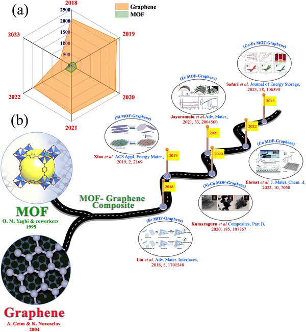
In this era, the limitations of renewable energy resources and the lack of fossil fuel energy are playing a crucial part in developing clean and sustainable energy sources in economically advanced ways.1–3 CO2 emission during the process generates an environmental problem. To solve these problems, extensive research is going on all over the globe, concentrating on clean, sustainable, and renewable energy resources that can replace fossil fuels.4,5 In this regard, solar energy, tidal energy, and wind energy have been considered as alternatives.6 But these energy sources are not available for an uninterrupted time or they depend on the time of day or location.7–10 Energy storage and conversion devices have become very important to the scientific community. Besides with the rapid development in means of transportation, such as fully electric vehicles, plug-in hybrids, and hybrid electric vehicles, and consumer electronics extending from laptops, to digital cameras, mobile phones, and emergency doors, the requirements for the power and energy density of energy storage devices have increased.11–14 The battery is the most frequently used energy storage device. High energy capacity batteries can be applied in many fields.15 But the lower power density of a battery provides a barrier to its application that requires a large power impulse. Supercapacitors can provide high power density and specific capacitance, a longer cycle life, a faster charge–discharge rate, excellent reversibility, a wide thermal operating range, cost-effectiveness, and self-operation in devices, all of which make supercapacitors an active area of research.16–29 These characteristics of supercapacitors are extensively used in gadgets such as electronic equipment, camera flashes, digital communication devices, by the military, in aerospace, as industrial accessories, etc.30–38 Supercapacitors comprise four main components: electrode materials, a current collector, electrolyte, and a separator.39 The ion permeability of the separator permits ionic charge transfer. Supercapacitors with high power densities, moderate energy density, and long cycle stability bridge the gap between traditional capacitors and batteries.40–45 The lower energy density of supercapacitors, compared with batteries and fuel cells, creates a challenge at this current time.46,47 So, researchers are motivated on a determined pathway to enhance the absolute energy of supercapacitors through the development of new electrodes and electrolytes, and through innovative device fabrication.48,49 However, a supercapacitor depends on two charge storage mechanisms: i.e., EDLCs and pseudocapacitors. In EDLCs, charge species are adsorbed onto the surface of the electrode. In contrast, in pseudocapacitors, intercalation of ion species occurs between the electrode and electrolyte interface, resulting in the faradaic redox reaction of the active materials.Different kinds of materials, including metal oxides, metal phosphides, graphene derivatives, covalent–organic frameworks (COFs), MOFs, and porous carbon materials, have been reported for their application in supercapacitors.7,50–66 In 1995, Yaghi and co-workers discovered MOFs, and since then MOFs have been widely used in various applications.67 This term became more popular when Yaghi and coworkers discovered the structure of MOF-5.68 MOFs built by connecting organic ligands with metal clusters, or metal ions69–73 made a bright appearance in the area of hybrid crystalline substances. The choice of metal ions or metal clusters with an appropriate organic ligand structure allows the formation of MOFs in different dimensions.37 Compared to other porous materials, the pore size of the framework could be easily controlled by altering the length of the organic linker. MOFs with tunable pore structures, redox-active metal centres, and large surface areas are bright candidates for electrode materials for supercapacitor applications.74,75 But their low conductivity property generates a problem for supercapacitor applications.76,77 However, the synergistic effect of bimetallic MOFs provides enhanced supercapacitor performance compared to monometallic MOFs. On the other hand, graphene has a large theoretical surface area, good electrochemical stability, high conductivity, and other distinct chemical and physical properties that have gathered significant attention for supercapacitor applications. The number of individual articles reported for supercapacitor applications in the last few years, expressly since 2018, using MOF and graphene, is provided in Fig. 1(a). The formation of a composite with graphene can overcome the drawbacks of MOFs and benefit from two-parent constituents. Combining hetero-structured MOFs with graphene enhances the electrical conductivity of the matrix, which is helpful for faster ionic movement in electrochemical reactions. Due to this, the interfacial interaction can be improved, ensuring faster charge storage kinetics. Also, the durability of the composite could be improved by integrating MOFs with graphene because of the increased contact area with the electrolytic ions. Agglomeration of graphitic layers in graphene oxide can be diminished by a composite with MOFs, resulting in a higher electro-active surface area in the materials. For these reasons, a few review articles have been published based on MOF–graphene composites, focusing on their synthesis and their potential applications for different purposes.78–84 But in the above-mentioned review articles, multiple applications of MOF–graphene composites are described. In this review article, we present a focused and updated discussion about the application of MOF–graphene composites in electrochemical supercapacitor applications. Measurement of the electrochemical performance of supercapacitors, types of supercapacitors, and materials for supercapacitors are discussed in this review article. We discuss the MOF–graphene composites thoroughly based on different metal-based MOF–graphene composites. The benefits of MOF–graphene composites in supercapacitor applications are also discussed with proper explanation in this section. We also give an idea of various other MOF-based composites and their derivatives for supercapacitor applications. Different types of MOF–graphene composites have flourished over time, and their supercapacitor applications have been explored (Fig. 1(b)).
2 Electrochemical performance measurement of supercapacitor electrode materials
The supercapacitor performance of an as-obtained electrode has been evaluated by performing various electrochemical measurements like cyclic voltammetry (CV), galvanostatic charge–discharge (GCD), and electrochemical impedance spectroscopy (EIS). One can obtain the values of basic parameters like current, voltage, and time from the above measures. From the values of the above parameters, it is possible to obtain the values of other related parameters, including specific capacitance, cyclic stability, energy density, power density, and charge transfer resistance of the supercapacitor. These parameters are essential for the supercapacitance performance of the electrode materials. From cyclic voltammetry, the specific capacitance (C) of an electrode could be calculated using the equation:where C is the specific capacitance (in F g−1), m is the mass of the active electrode (in g), ν is the scan rate (in Vs−1), V1 and V2 are the potential limits (in V) and
 indicates the area under the CV curve over an operational voltage range. The specific capacitance from the galvanostatic charge–discharge (GCD) analysis can be determined using the following equation:
where I indicates the steady discharge current applied (in A) for GCD measurement, m is the mass of the active electrode (in g),
 is the area under the discharge curve, and (V2 − V1) is the working potential window (in V). The energy density (E) and the power density (P) of a supercapacitor can be calculated as:
and
3 Types of supercapacitor
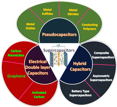
Supercapacitors can be divided into three categories based on the pathway of energy storage: (i) electrical double-layer capacitors (EDLCs), (ii) pseudocapacitors, and (iii) hybrid capacitors. A classification of supercapacitors based on charge storage mechanism is provided in Fig. 2.3.1 Electrical double-layer capacitors (EDLCs)
EDLCs are formed by the combination of two electrodes and an electrolyte. In EDLCs, charge storage is possible either electrostatically or through a non-faradaic process, which can be generated from the accumulation of the charges at the electrode–electrolyte interface. The electrical double layer is the principle behind energy storage in EDLCs. So, the pore size distribution and the accessible surface/interface features of the electrode materials generally determine the capacitance of EDLCs.85 This charge separation allows the formation of the electrical double layer. In EDLCs, charge storage occurs through a surface phenomenon. EDLCs allow quick energy uptake, power performance, and energy delivery. Carbon-containing substances, such as graphene, activated carbon, or carbon nanotubes, are usually applied as electrode materials for EDLCs. These materials possess high conductivity, a large surface area, and high-temperature stability.86 EDLCs possess higher power density as well as superb charge–discharge cycling stability, as the chemical reaction occurs at the electrode surface during the charge–discharge process.85 But EDLCs have a relatively low energy density and limited specific capacitance.87,88 Enhancing the conductivity and controlling the pore size and surface area are the most fruitful approaches to achieving high capacitance in an EDLC.89,903.2 Pseudocapacitors
In pseudocapacitors, a quick faradaic redox reaction of electroactive materials at the interface is involved where the charge transfer has occurred, which is the reason behind the energy storage. The larger specific capacitance and energy densities of pseudocapacitors compared to EDLCs are due to the involvement of the faradaic process. Usually, conducting polymers and metal oxides, especially transition metal oxides, sulfides, selenides, and nitrides, are used as electrode materials for pseudocapacitors.3.3 Hybrid capacitors
EDLCs exhibit good power performance and cyclic stability, whereas pseudocapacitors possess a high specific capacitance value. Hybrid capacitors are special supercapacitors that combine EDLCs (non-faradaic) and pseudocapacitors (faradaic).4 Materials for supercapacitors
Different kinds of materials, including metal oxides, metal phosphides, graphene derivatives, COFs, MOFs, and porous carbon materials, have been reported for application in supercapacitors.7,50–634.1 Metal–organic frameworks (MOFs)
MOFs designed by connecting organic ligands with metal clusters, or metal ions69–73 have made a bright appearance in the area of hybrid crystalline substances as highly encouraging materials with diverse structural characteristics and have found application for different purposes, such as gas storage, gas separation, magnetism, catalysis, sensing, or drug delivery, over the last two decades.93–107 The interconnected pores within MOFs provide a distinctively confined environment where new physical and chemical properties can be developed. MOFs are generally synthesized via solvothermal techniques.108–112 But mechanochemical methods,113–116 electrochemical routes,117–120 sonochemical routes,121–124 microwave-assisted syntheses,125–128 and slow-layer diffusion techniques129–133 are also used for the preparation of MOFs. In MOFs, the pore size and surface area can be tuned by using suitable ligands as the linkers. There is a possibility of incorporating a particular group within the framework structure. The shape and size-controlled synthesis of MOFs at macro and nanoscales is also possible. In comparison with other porous materials, the pore size of the framework could be easily controlled by altering the length of the organic linker. MOFs can be deposited onto various substrates to obtain composites with other carbon-based supports to improve their conducting and electrical properties. MOFs can be assembled with graphene sheets to form composites after dispersing the nanosheets into the MOF parent solutions.134,135 Many MOFs could be synthesized with different structures, as diverse choices of linker and metal are possible. Recently, their application has been reported for supercapacitor purposes.74,754.2 Graphene
Among all the most propitious allotropes of carbon, graphene has attracted massive attention in the nanomaterials field due to two distinctive properties: good electrical behaviour and an excellent robust structure.136 On the other hand, graphene oxide can be synthesized easily from graphite mesh, and is a graphene congener with countless oxygen-bearing functionalities, which allows the construction of a broad spectrum of new functional groups.137 Also, the nanostructure of graphene oxide is made off the basal plane, which is enriched with epoxy, hydroxyl, and carboxylic acid functional groups. Due to the unique structure of carbon containing one-atom-thick layers arranged in a honeycomb unit, graphene oxide can be used as a building block to efficiently synthesize 2D porous hybrid nanomaterials. Recently, graphene has been selected as an encouraging carbon-based material with huge possibilities in the industrial field to favour different catalytic organic transformation reactions such as hydration of alkenes,138 oxidation of thiols,139 and aerobic oxidation of alcohols, which can be converted into the associated aldehydes and ketones.140 However, it is relevant to state that graphene oxide is hydrophilic due to the existence of a broad range of oxygen-bearing groups on the basal planes and edges, which can facilitate the grafting of the active metal ions onto the surface. Optimization followed by standardization of the chemical reaction and the development of an environmentally-friendly chemical reaction can be successfully performed via the participation of a porous material containing suitable organic groups inside the pore wall, which can provide fascinating technological and energy-related improvements.4.3 MOF–graphene composites
In the case of MOF, the vital role of the metal ion is to form the backbone of the framework in supercapacitor applications. Different metal-based MOFs are reported to be used to prepare MOF–graphene composites, which are superior to pure MOF and graphene. The benefits are as follows: (i) the aggregation of two substances could be interrupted owing to the inclusion of graphene-based materials; (ii) high electrical conductivity could be maintained over the electrode; (iii) the cycling stability of the electrode could be increased at the time of the charge–discharge process; and (iv) the structural feature of the pseudocapacitive material could remain unaltered and inhibit detachment from the graphene surface at the time of the charge–discharge process. Here, we discuss the supercapacitor application of MOF–graphene composites based on the different metal ions involved in building the MOF structure (see the detailed illustration in Fig. 3).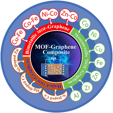 | ||
| Fig. 3 Schematic presentation of different metal-ion-based MOF–graphene composites for supercapacitor applications. | ||
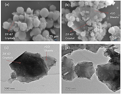 | ||
| Fig. 4 FESEM images of (a) ZIF-67 and (b) ZIF-67/rGO. (c) and (d) TEM images of the ZIF-67/rGO composite. Reproduced from ref. 141 with permission from American Chemical Society, Copyright 2018. | ||
Wang and co-workers synthesized nanocubes of ZIF-67 by mixing 2-methyl imidazole and Co(NO3)2·6H2O in an aqueous solution containing hexadecyltrimethylammonium bromide (CTAB).142 A room-temperature one-pot stirring method was used for the preparation of graphene oxide (GO)-wrapped ZIF-67 nanocomposites with different concentrations of GO. The supercapacitance performance with respect to the specific capacitance and cyclic stability of the composite was better than those of pure GO or ZIF-67 nanocubes. 6 M KOH solution was utilized as the electrolyte to check the supercapacitance behaviour in a three-electrode system. In this ZIF-67 and ZIF-67/GO-n composite, direct involvement of two redox couples occurs, and a pseudocapacitor characteristic was observed. The faradaic reaction between Co2+/Co3+ and Co3+/Co4+ was implicated in the action. Upon an increase in scan rate, the specific capacitance value for all the composites decreases due to the limitation of ion diffusion rate. The composite containing 2 wt% of GO, i.e., ZIF-67/GO-2, showed a specific capacitance of 100.47 F g−1 at a scan rate of 5 mV s−1. The specific capacitance values of the ZIF-67/GO-n nanocomposites from the GCD data were higher than those of single GO or single ZIF-67. The specific capacitance value for the ZIF-67/GO-2 composite was 70.76 F g−1 at a lower current density of 1 A g−1 and it reduced to 46.36 F g−1 at a current density of 20 A g−1. A chronopotentiometry technique at 10 A g−1 was used to measure the cycle life of ZIF-67/GO-2. After performing the experiments for 600 cycles, ZIF-67/GO-2 exhibited an increase in capacitance value to 62.0 F g−1, and thereafter, a minute rise in capacitance value was observed for cycles in the range 600 to 1000. The authors suggested that the activation of the ZIF-67/GO-2 composite over time is the reason behind the increase in capacitance value with the cycle charge–discharge process.
Azadfalah et al. demonstrated an in situ synthesis technique to prepare Co MOF/graphene composites using Co(NO3)2·6H2O, methyl imidazole, and graphene (Fig. 5).143
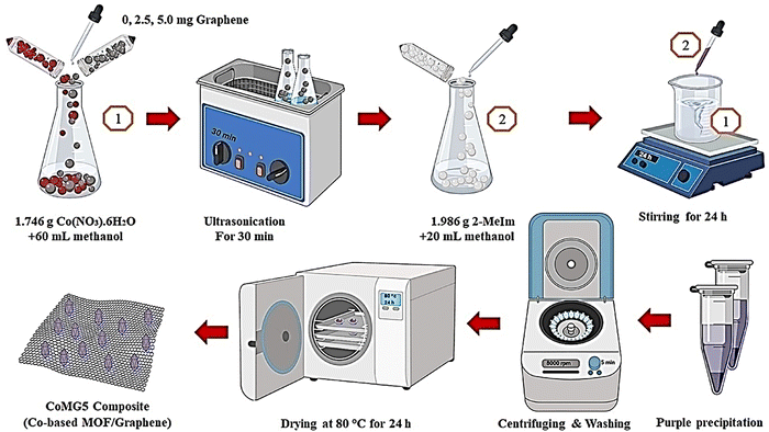 | ||
| Fig. 5 The schematic production process of the CoMGX nanocomposites. Reproduced from ref. 143 with permission from Elsevier Ltd, Copyright 2021. | ||
Three-electrode systems were used to perform supercapacitor experiments in a 6 M KOH aqueous solution. Cyclic voltammetry experiments for all the samples were performed with a scan rate of 10 mV s−1 from −0.1 to 0.6 V (Fig. 6(a)). Here, capacitive performance is controlled by battery-like behaviour and redox reactions. The nitrogen adsorption–desorption analysis suggested that the effective surface area of the active materials is increased due to the addition of graphene to CoM. Also, the CV experiments revealed the reversibility and capacitive characteristics of all three substances at various scan rates from 10 to 100 mV s−1 (Fig. 6(b)–(d)). With the rise in scan rate, the lack of change in the CV curve indicated good capacitance behaviour due to the diffusion of ions in a faster mode onto the nanocomposites.
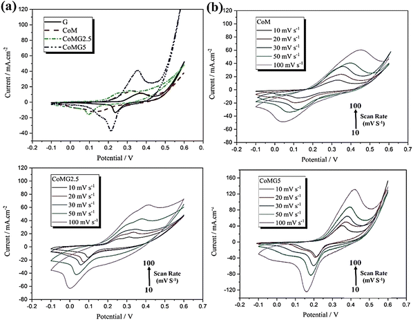 | ||
| Fig. 6 The CV curves of (a) G, CoM, CoMG2.5, and CoMG5 at a scan rate of 10 mV s−1, (b) CoM, (c) CoMG2.5 and (d) CoMG5 electrodes at different scan rates (10–100 mV s−1) in 6 M KOH. Reproduced from ref. 143 with permission from Elsevier Ltd, Copyright 2021. | ||
The discharge curve for all the electrodes in the GCD experiments showed nonlinear behaviour due to the redox reactions at the electrode–electrolyte interface, suggesting superior capacitance behaviour and a reversible nature in electrochemical performance. EIS measurements indicated that CoMG5 has the lowest charge transfer resistance, Rct. All the composites have lower Rct values than CoM, which shows that the addition of graphene to CoM increases its electrical conductivity, and the reduction in resistance of the substance occurs through the facilitation of OH− ion diffusion into the active substance surface. The CoMG5 electrode showed the highest capacity of 549.96 F g−1 due to the synergic effect of Co MOF and graphene in the composite.
Srivastava and co-workers employed a cost-effective, simple mechanochemical synthesis method to synthesize a CoBTC/GNS composite with a high surface area using cobalt acetate, benzene-1,3,5-tricarboxylic acid (BTC), graphene oxide, and glucose.144 The CoBTC/GNS composite showed low crystallinity owing to the presence of GNS. The generation of a sandwich structure confirms the presence of CoBTC MOF rods in between GNS. Due to this arrangement, the composite exhibited a specific capacitance of 608.2 F g−1 at a current density of 0.25 A g−1 in a 1 M KOH solution. At the time of potential scanning, the following quasi-reversible redox reactions occurred:
| Co2+ + 3OH− = CoOOH + H2O + e− |
| CoOOH + OH− = CoO2 + H2O + e− |
| [Ni3(OH)3(C8H4O4)2·(H2O)4]·2H2O + OH− ↔ [Ni3O(OH)(C8H4O4)2·(H2O)4]·2H2O + H2O + e− |
Using a facile hydrothermal method, Liu and co-workers synthesized Ni MOF nanospheres on reduced graphene oxide (Ni-MOF/rGO).146 The material for supercapacitor application was prepared by annelation at 300 °C (Ni-MOF/rGO-300). Electrochemical performances of Ni-MOF/rGO-300, Ni-MOF/rGO, and Ni-MOF were studied with a scan rate of 100 mV s−1 in 6 M KOH. The confined spaces of Ni-MOF and Ni-MOF/rGO are smaller than that of Ni-MOF/rGO-300. In the presence of OH−, all the electrodes exhibit oxidation and reduction peaks, with reversible redox reactions of Ni2+/Ni3+. In the GCD curves, Ni-MOF/rGO-300 displayed the greatest discharging process among the three modified electrodes. The obtained capacitance values at a current density of 1 A g−1 for Ni-MOF, Ni-MOF/rGO, and Ni-MOF/rGO-300 electrodes were 446, 529, and 954 F g−1, respectively. The synergistic effects between Ni-MOF and rGO provide great capacity performance for the Ni-MOF/rGO-300 composite. The internal resistance RS is smallest for the Ni-MOF/rGO-300 electrode, and its value is 0.56 Ω, resulting from the extremely aligned structure and additional reduction of GO by the calcination process. Ni-MOF/rGO-300 showed a specific capacitance of 954 F g−1 at 1 A g−1. 80% retention of capacitance value was observed for the Ni-MOF/rGO-300 electrode after the 4000th charge–discharge cycle at 5 A g−1. The potential application of Ni-MOF/rGO-300 was studied by fabricating an asymmetric supercapacitor using Ni-MOF/rGO-300.
Xiao et al. reported the development of a 2D LEG (graphene with low defect density and excellent electrical conductivity)-based Ni-MOF, GM-LEG@Ni-MOF, under solvothermal reaction conditions (Scheme 1).147
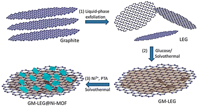 | ||
| Scheme 1 Schematic synthesis procedure of GM-LEG@Ni-MOF composites. Reproduced from ref. 147 with permission from American Chemical Society, Copyright 2019. | ||
GM-LEG@Ni-MOF displayed a specific capacitance of 987.6 F g−1 when the current density was fixed at 0.5 A g−1 in 3 M KOH solution, where 85.6% retention of capacitance was observed after 3000 cycles. These results are better than those of the pure Ni-MOF and LEG@Ni-MOF counterparts. Abundant oxygen functionalities in LEG were achieved through the glucose modification protocol. Improvement in the solution processability of LEG and assistance to the controlled growth of Ni-MOF nanosheets around LEG are made possible by the presence of abundant oxygen functionalities. A higher amount of stable energetic sites was furnished due to the presence of a lamellar heterostructure. These energetic sites can boost the adsorption and transmission of ions and electrons in supercapacitor use.
Kim and co-workers synthesized Ni-MOF/rGO composite by using a hydrothermal method and used it in a supercapacitor application.148 6 M KOH was used to perform electrochemical supercapacitance experiments for rGO, Ni-MOF, and Ni-MOF/rGO. At a current density of 1 A g−1, the observed specific capacitance values were 987.3 F g−1, 8 F g−1, and 847.3 F g−1 for MOF/rGO, rGO, and Ni-MOF, respectively. Ni-MOF/rGO exhibited a specific capacitance of 1154.4 F g−1 at a current density of 0.66 A g−1 with a discharge time of 885 s. After 3000 cycles, it showed 90% retention of the initial specific capacitance value. The increase in specific surface area and active sites of the electrode due to Ni MOF was the probable reason behind the higher value of the specific capacitance of the composite.
He et al. utilized Ni(NO3)2·6H2O, graphene oxide (GO), and 4,4′-biphenyl dicarboxylic acid (BPDC) to synthesize Ni-BPDC/GO following a hydrothermal technique.149 Detailed characterization of Ni-BPDC/GO was carried out using PXRD, SEM, Raman, and TEM analyses. The electrochemical performance of Ni-BPDC/GO and Ni-BPDC was studied in 6 M KOH solution in a three-electrode system. From the GCD curve, calculated specific capacitance values were 460 F g−1 and 630 F g−1 for Ni-BPDC and Ni-BPDC/GO-3, respectively, at 1 A g−1. Ni(III) and Ni(IV) redox couples are involved here. The EIS measurement values of charge transfer resistance (Rct) were 5.96 Ω and 2.23 Ω for Ni-BPDC and Ni-BPDC/GO-3, respectively. To check the cyclic stability of the composite Ni-BPDC/GO-3, 10![[thin space (1/6-em)]](https://www.rsc.org/images/entities/char_2009.gif) 000 cycles were performed at 5 A g−1. For the first 2400 cycles, the capacitance value decreased due to Ni ions bonding with OH− ions. Then, the specific capacitance value remained constant, resulting in 56.5% retention of capacitance value after 10
000 cycles were performed at 5 A g−1. For the first 2400 cycles, the capacitance value decreased due to Ni ions bonding with OH− ions. Then, the specific capacitance value remained constant, resulting in 56.5% retention of capacitance value after 10![[thin space (1/6-em)]](https://www.rsc.org/images/entities/char_2009.gif) 000 cycles. An asymmetric supercapacitor was constructed for practical application purposes using rGO as the negative electrode and Ni-BPDC/GO-3 as the positive electrode in a two-electrode setup. The asymmetric supercapacitor exhibited the highest energy density of 16.5 W h kg−1 at a power density of 250 W kg−1.
000 cycles. An asymmetric supercapacitor was constructed for practical application purposes using rGO as the negative electrode and Ni-BPDC/GO-3 as the positive electrode in a two-electrode setup. The asymmetric supercapacitor exhibited the highest energy density of 16.5 W h kg−1 at a power density of 250 W kg−1.
Das and co-workers recently synthesized Ni-MOF@GO composites with different wt% of GO.150 The characterization of the composites was performed using PXRD, SEM, TGA, BET, and XPS analyses. Electrochemical experiments were performed using a three-electrode system in 6 M KOH. From the GCD experiment, the obtained specific capacitance value for IITKGP-20A-GO3 was ∼840 F g−1 at 2 A g−1. IITKGP-20A-GO3 revealed higher cyclic stability compared to the MOF when the stability was checked by performing 5000 GCD cycles at a current density of 15 A g−1. The authors suggested that the increase in electrochemical redox active sites that are responsible for the fruitful transfer of the ions of the electrolytes and the inclusion of RGO lowered the resistivity of the composite through the synergistic effect of Ni-MOF and RGO sheets. For a real application, an asymmetric supercapacitor was fabricated. The two-electrode system showed a specific capacitance value of 111.4 F g−1 at 2 A g−1. It supplied an energy density of 30.7 W h kg−1 at a power density of 388.5 W kg−1 with 84% capacitance retention after 7000 cycles. The constructed device can illuminate an LED light for about 3 minutes.
Chen et al. prepared GO/MOF composites (Ni-BTC@GO) through an in situ synthesis technique (Fig. 7) by varying the amount of GO sheets.151
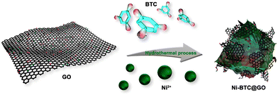 | ||
| Fig. 7 The preparation process of Ni-BTC@GO composites. Reproduced from ref. 151 with permission from American Chemical Society, Copyright 2023. | ||
They determined the amount of GO in Ni-BTC@GO by TG-DTG study. Electrochemical experiments were conducted in a three-electrode system utilizing 6 M KOH solution as an electrolyte (Fig. 8). For Ni-BTC@GO 2, the combined area of the CV curves is the highest (Fig. 8a). Fig. 8b illustrates GCD profiles at 1 A g−1, with Ni-BTC@GO 2 having the most significant charge–discharge time. Fig. 8c displays Ni-BTC@GO 2 CV profiles with scan rates varying between 2 and 100 mV s−1. The change in the GCD profile with variation in current density for Ni-BTC@GO 2 is shown in Fig. 8d. The Rct values were 7.649 Ω and 7.065 Ω for Ni-BTC and Ni-BTC@GO 2, respectively. Ni-BTC@GO 2 showed 84.47% retention of specific capacitance values after performing 5000 GCD cycles at 10 A g−1 current density. They also assembled an asymmetric capacitor, which exhibited an energy density of 40.89 W h kg−1 at 800 W kg−1. They suggested that the conductivity of Ni-BTC is enhanced by the incorporation of GO sheets, resulting in a reduction in the ion transport path. This increases the specific capacitance values.
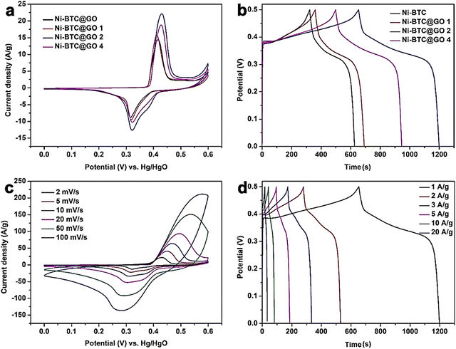 | ||
| Fig. 8 (a) CV curves of Ni-BTC and Ni-BTC@GO composites at 2 mV s−1, (b) GCD curves of Ni-BTC and Ni-BTC@GO composites at 1 A g−1, (c) CV curves of Ni-BTC@GO 2 at 2–100 mV s−1, and (d) GCD curves of Ni-BTC@GO 2 at 1–20 A g−1. Reproduced from ref. 151 with permission from American Chemical Society, Copyright 2023. | ||
Khiew and coworkers reported new Ni-MOF/graphene nanocomposites for supercapacitor applications.152 They synthesized MOFs with different morphologies in different solvents through a solvothermal method (Fig. 9). MOFs synthesized in a binary solvent mixture of ethylene glycol (EG) and DMF have a 3D flower-like morphology. Then, an Ni-MOF–graphene nanocomposite was prepared via the incorporation of graphene nanosheets into Ni-MOF. The as-synthesized Ni-MOF–graphene nanocomposite was characterized by PXRD, FESEM, EDX, TEM, FTIR, and TGA analyses. Electrochemical experiments were conducted in a two-electrode system using 2 M NaCl and 2 M KOH solutions as electrolytes. In 2 M NaCl electrolyte, the FG_Gr1.0, nanocomposite exhibited a specific capacitance of 111.68 F g−1 at 0.3 A g−1. In 2 M KOH, the specific capacitance for the FG_Gr1.0 nanocomposite was 126.21 F g−1 at a current density of 0.3 A g−1. 14.68 W h kg−1 and 291.82 W kg−1 were the energy density and power density for FG_Gr1.0 in 2 M NaCl, respectively. 97.70% retention of capacitance and Coulombic efficiency of 89.05% were obtained after carrying out 10![[thin space (1/6-em)]](https://www.rsc.org/images/entities/char_2009.gif) 000 GCD cycles at a current density of 1.5 A g−1 in 2 M NaCl compared to electrode materials synthesized in other solvent systems. The 3D flower-like morphology of the MOF assists the process of ion transfer and produces a large disclosed surface to store a huge number of charges. At the same time, a reduction in intrinsic electrochemical resistance is possible due to the benefit of the unique structure resulting in an enhancement in supercapacitance performance. Besides that, the incorporation of highly conductive graphene nanosheets further increases the supercapacitor behaviour.
000 GCD cycles at a current density of 1.5 A g−1 in 2 M NaCl compared to electrode materials synthesized in other solvent systems. The 3D flower-like morphology of the MOF assists the process of ion transfer and produces a large disclosed surface to store a huge number of charges. At the same time, a reduction in intrinsic electrochemical resistance is possible due to the benefit of the unique structure resulting in an enhancement in supercapacitance performance. Besides that, the incorporation of highly conductive graphene nanosheets further increases the supercapacitor behaviour.
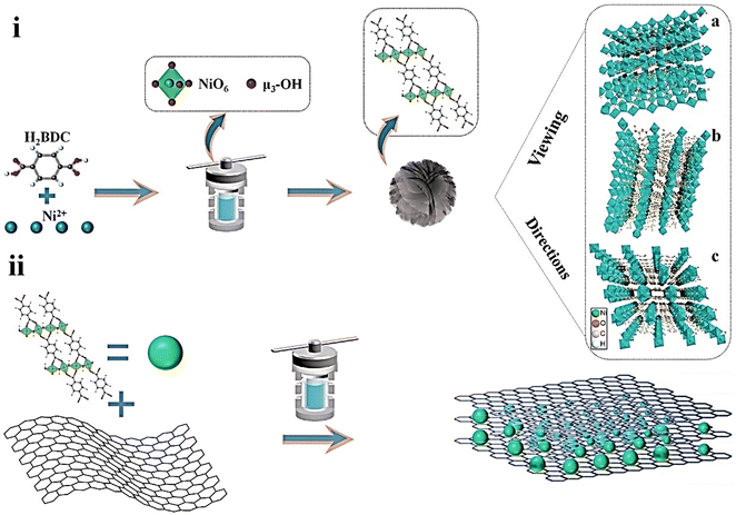 | ||
| Fig. 9 Schematic illustration of the fabrication of (i) hierarchical Ni-MOFs and (ii) FG_Gry via a solvothermal method. Reproduced from ref. 152 with permission from Elsevier Ltd, Copyright 2022. | ||
Rai and co-workers synthesized a Cu-MOF (HMRL-1) using a tetracarboxylic-acid-based ligand H4L (3,3′,5,5′-tetracarboxydiphenylmethane) (5,5′-MDIP ligand) as linker with Cu(NO3)2·3H2O under solvothermal conditions.154 The fabrication of the composite (HMRL-1/R) was done using the as-synthesized MOF and reduced graphene oxide (R) through a simple ultrasonication approach (see Scheme 2). The 3D porous MOF with a suitable channel structure and redox-active Cu2+ centres enhanced the ion transport. The electrochemical performance of the composite showed hybrid capacitive features due to the combination of the EDLC behaviour of rGO and pseudocapacitive behaviour of Cu-MOF, respectively, where 366.6 F g−1 specific capacitance was observed at a current density of 1 A g−1 in 1 M Na2SO4. After performing 4000 cycles, 83.30% retention of capacitance was observed. These results are far better than those of HMRL-1 or R. In addition, preventing restacking of 2D rGO sheets increases the production area for ion adsorption due to the presence of MOFs in the rGO matrix.
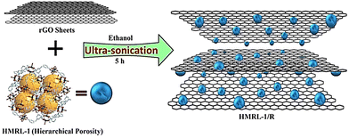 | ||
| Scheme 2 Synthesis of HMRL-1/R. Reproduced from ref. 154 with permission from Elsevier Ltd, Copyright 2021. | ||
The acoustomicrofluidic method was used by Ehrnst et al. to synthesize homogeneous quasi-2D MOF–graphene oxide (q-2D-MOF/rGO) planar heterostructures without requiring conductive binders or scaffolds.155 The quasi-2D MOFs have a high surface area to volume ratio and dense exposure of Cu sites on their surface, which increases effective Cu/GO coordination and reduces GO to reduced graphene oxide (rGO) without disturbing the structural characteristics of the MOF. A detailed characterization of the composite was performed using PXRD, FTIR, TGA, XPS, Raman spectroscopy, helium ion microscopy, and BET analyses. A three-electrode arrangement in 1 M H2SO4 electrolyte solution was used to perform the supercapacitor experiments. The composite exhibited a quasi-rectangular shape in cyclic voltammetry due to the attribution of the rGO and Cu-BTC MOF components. A deviation in GCD data from the triangular trace of double-layer capacitance was observed. The composite exhibited a gravimetric capacitance of 292 F g−1 at a current density of 1 A g−1.
Mohanadas et al. reported the preparation of a Cu-MOF and rGO composite, namely MrGO, for supercapacitor applications.156 MrGO was characterized by PXRD, FESEM, FTIR, and Raman spectroscopy. A three-electrode setup was utilized to perform supercapacitor experiments in 1 M KCl. The MrGO electrode exhibited a specific capacitance of 208.9 F g−1, which was quite large in comparison to those of Cu-MOF of 143.7 F g−1 or rGO of 100.2 F g−1. The charge transfer resistance (Rct) value of 0.95 Ω was much lower than those of Cu-MOF or rGO. An asymmetric device was prepared using vanadium oxide/reduced graphene oxide (VrGO) as the positive electrode and MrGO composite as the negative electrode. This device worked over a wide potential range (0–1.4 V) and exhibited a specific capacitance of 483.9 F g−1 at a scan rate of 5 mV s−1. It exhibited good specific energy and specific power of 31.2 W h kg−1 and 656.4 W kg−1, respectively. The asymmetric device retained 92% of its initial capacitance after performing 4000 CV cycles.
Krishnan et al. used porous piperazine (N) functionalized Cu-MOF (C) and reduced graphene oxide (R) for the fabrication of a hybrid composite Cu-MOF/rGO (CR) using simple ultrasonication.157 Cu-MOF/rGO was characterized by PXRD, FTIR, TGA, SEM, TEM, and BET analyses. CV and GCD experiments were carried out for Cu-MOF, reduced graphene oxide, and hybrid composite Cu-MOF/rGO (CR) using a three-electrode arrangement in 1 M Na2SO4 solution. A detailed description of the GCD experiments is given in Fig. 10. Fig. 10(a) compares the GCD profiles for C-GCE, R-GCE, and CR-GCE at 1 A g−1. From the charge–discharge data, the obtained values of specific capacitances were 867.09, 284.41, and 135 F g−1 for CR-GCE, R-GCE, and C-GCE at a current density of 1 A g−1 (Fig. 10(b)). Fig. 10(c) shows the GCD curves for CR-GCE at various current densities. The fluctuation in the specific capacitances for C-GCE, R-GCE, and CR-GCE depending on the current density is shown in Fig. 10(d).
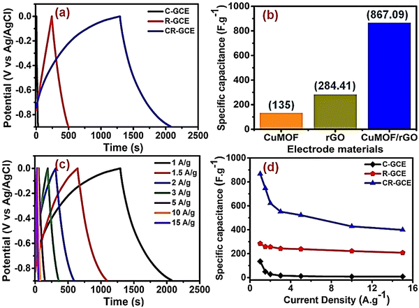 | ||
| Fig. 10 (a) Comparison of the GCD profiles of C-GCE, R-GCE, and CR-GCE at 1 A g−1 current density in 1 M Na2SO4; (b) specific capacitances of C-GCE, R-GCE, and CR-GCE electrodes at 1 A g−1; (c) GCD profiles of CR-GCE at different current densities (1–15 A g−1); and (d) specific capacitance variations of C-GCE, R-GCE, and CR-GCE with changing current densities (1–15 A g−1). Reproduced from ref. 157 with permission from Elsevier Ltd, Copyright 2022. | ||
The high specific capacitance of CR-GCE is due to the fact that the synergistic effect of R and C allows lower internal resistance, increases ion diffusion, enhances charge transfer kinetics, and provides a larger active surface area. CR showed 131.65% retention of the initial specific capacitance after performing the GCD experiments for 5000 cycles. They showed that at the time of the cycling process, electrochemical activation of the CR composite occurs, increasing the surface wettability and active electrochemical sites, resulting in a higher specific capacitance. As a result, the electrolyte–electrode interaction increases and enhances the efficient diffusion of electrolyte ions into the electrodes. For a real application, a symmetric supercapacitor device was assembled using the CR composite. This device exhibited a maximum energy density of 30.56 W h kg−1 at a power density of 0.6 kW kg−1. A maximum power density of 12 kW kg−1 was observed at an energy density of 14.59 W h kg−1. The symmetric device showed 90.07% conservation of capacitance after carrying out 10![[thin space (1/6-em)]](https://www.rsc.org/images/entities/char_2009.gif) 000 charge–discharge cycles.
000 charge–discharge cycles.
Sawangphruk and co-workers reported the synthesis of a reduced graphene oxide–MOF composite (10 wt% rGO/HKUST-1) through the utilization of 10 wt% rGO and HKUST-1.158 The BET surface area, specific pore volume, and average pore diameter of 10 wt% rGO/HKUST-1 were 1241 m2 g−1, 0.78 cm3 g−1, and 8.2 nm. This pore size is suitable for uptaking and releasing electrolytes. Here, 0.5 M Na2SO4 solution was used as an electrolyte. 10 wt% rGO/HKUST-1 coated on flexible carbon fiber paper (CFP) was used as an electrode in a three-electrode configuration. The 10 wt% rGO-HKUST-1 composite showed a specific capacitance of 385 F g−1 at a current density of 1 A g−1. This mesoporous 10 wt% rGO-HKUST-1 composite has sufficient well-ordered tunnels suitable for the insertion/extraction of hydrated Na+ and H3O+ into/from the electrode. A symmetrical supercapacitor set-up of 10 wt% rGO/HKUST-1 showed a specific energy of 42 W h kg−1 and a specific power of 3100 W kg−1. 98.5% retention of capacitance occurred after 4000 cycles.
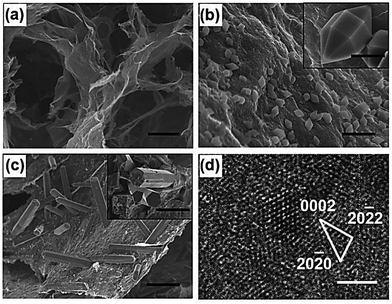 | ||
| Fig. 11 SEM and TEM images of GA, GAMOF, and GAMOF(Fe3+) composites. (a) SEM image of GA (scale bar: 20 μm). (b) Low- (scale bar: 2 μm) and high-magnification SEM images (inset; scale bar: 500 nm) of GAMOF. (c) Low- (scale bar: 2 μm) and high-magnification SEM images (inset, scale bar: 500 nm) of GAMOF(Fe3+). (d) HRTEM image of GAMOF(Fe3+) (scale bar: 2 nm). Reproduced from ref. 159 with permission from WILEY-VCH, Copyright 2018. | ||
The as-prepared materials were characterized through XRD, IR, and XPS. Cyclic voltammetry experiments were performed for GA, GAMOF, and GAMOF(Fe3+). The increased capacitance changes of GAMOF and GAMOF(Fe3+) are mainly due to the alteration of electric double-layer properties as affected by MOF. For GA and GAMOF(Fe3+), the charge–discharge profile is symmetric, while for GAMOF, the charge–discharge profile is asymmetric. The asymmetric nature comes out due to some irreversible faradaic processes. The transport of ions and channels for diffusion was found in the mesopores and micropores of GA, and the storage of ions was obtained from the micropores of MOF, where the retention ratios for GA, GAMOF, and GAMOF(Fe3+) were 66.2, 44.7 and 74.4%, respectively, after 10![[thin space (1/6-em)]](https://www.rsc.org/images/entities/char_2009.gif) 000 cycles.
000 cycles.
![[thin space (1/6-em)]](https://www.rsc.org/images/entities/char_2009.gif) :
:![[thin space (1/6-em)]](https://www.rsc.org/images/entities/char_2009.gif) 100 and 20
100 and 20![[thin space (1/6-em)]](https://www.rsc.org/images/entities/char_2009.gif) :
:![[thin space (1/6-em)]](https://www.rsc.org/images/entities/char_2009.gif) 100, and indexed as Zn-MOF–rGO10 and Zn-MOF–rGO20, respectively. The electrochemical behaviour of the composites was studied in a 3 M KOH solution using a three-electrode configuration. The Zn-MOF–rGO20 electrode showed a specific capacity of 205 C g−1 at a current density of 1 A g−1. A symmetric device with a Zn-MOF–rGO20 electrode showed a specific energy density of 7.1 W h kg−1 at a power density of 0.4 kW kg−1. A charge transfer resistance (Rct) value of 5.95 Ω was observed at the electrode–electrolyte interface of the Zn-MOF–rGO20 symmetric device. Using power law, they observed that the diffusion-controlled pathway of the electrochemical charge storage mechanism contributes more than the pseudocapacitive-controlled pathway. The authors suggested that the synergistic effect between ZnMOF and rGO is the reason behind the supercapacitance performance. Firstly, a commendable pathway for the transfer of charge and an active surface area were obtained due to the porous Ceratophyllum-like surface structure of ZnMOF. Secondly, electron transfer during the charge–discharge process is promoted by attaching electrically conductive components to the rGO sheets, resulting in good supercapacitor behaviour. In addition, the porous rGO increases the surface area for electrolyte–electrode contact, boosting the supercapacitor performance of the composite.
100, and indexed as Zn-MOF–rGO10 and Zn-MOF–rGO20, respectively. The electrochemical behaviour of the composites was studied in a 3 M KOH solution using a three-electrode configuration. The Zn-MOF–rGO20 electrode showed a specific capacity of 205 C g−1 at a current density of 1 A g−1. A symmetric device with a Zn-MOF–rGO20 electrode showed a specific energy density of 7.1 W h kg−1 at a power density of 0.4 kW kg−1. A charge transfer resistance (Rct) value of 5.95 Ω was observed at the electrode–electrolyte interface of the Zn-MOF–rGO20 symmetric device. Using power law, they observed that the diffusion-controlled pathway of the electrochemical charge storage mechanism contributes more than the pseudocapacitive-controlled pathway. The authors suggested that the synergistic effect between ZnMOF and rGO is the reason behind the supercapacitance performance. Firstly, a commendable pathway for the transfer of charge and an active surface area were obtained due to the porous Ceratophyllum-like surface structure of ZnMOF. Secondly, electron transfer during the charge–discharge process is promoted by attaching electrically conductive components to the rGO sheets, resulting in good supercapacitor behaviour. In addition, the porous rGO increases the surface area for electrolyte–electrode contact, boosting the supercapacitor performance of the composite.
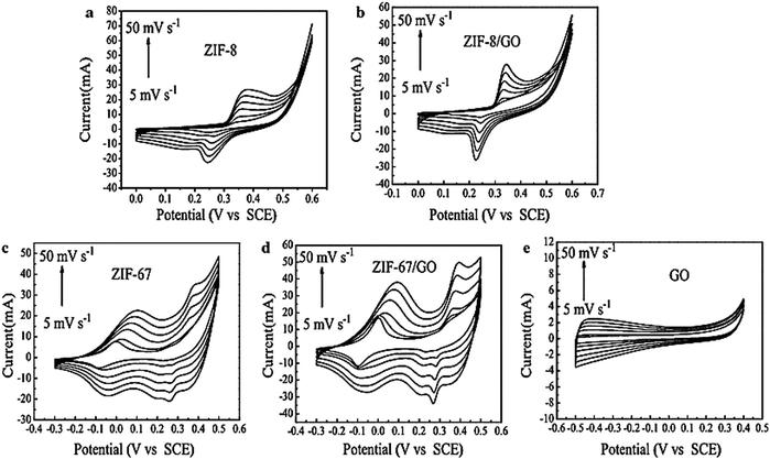 | ||
| Fig. 12 Cyclic voltammetry curves of (a) ZIF-8, (b) ZIF-8/GO, (c) ZIF-67, (d) ZIF-67/GO, and (e) GO at increasing voltage scan rates of 5, 10, 20, 30, 40, and 50 mV s−1. Reproduced from ref. 161 with permission from Springer Science, Copyright 2016. | ||
The pseudocapacitance properties of ZIF and ZIF/GO composites were confirmed from their CV curves. The shift of cathode peaks to higher voltage and the shift of anodic peaks to lower values occurred when the scan rate increased. At a higher scan rate, an increase in electric polarization and an irreversible reaction are the reasons behind the cathodic and anodic peak shifts. The specific capacitance of ZIF-8/GO was 160 F g−1 with a scan rate of 5 mV s−1. The authors observed that the specific capacitance value of the ZIF-8/GO composite increased with a rise in scan rate, which was more than twice that of ZIF-8. So, the specific capacitance of the ZIF-67/GO electrode material was 252 F g−1, greater than that of ZIF-67 of 189 F g−1. The GCD curves are nonlinear for all the samples, indicating that the samples behave like pseudocapacitors. ZIF-67/GO showed much higher (202 F g−1) capacitance at a current density of 1 A g−1 than ZIF-8/GO (95 F g−1) or GO (73 F g−1). However, two reasons are responsible for the excellent supercapacitor performance: the good conductive feature of GO assists ion diffusion and electron transport into the redox area of the composite.
Additionally, the very good porous structure and large surface area of ZIF-67 furnish high energy storage capacity. In pure ZIF, the distribution is less than that of ZIF developed on GO, and the active centres in ZIF are less than those of ZIF/GO, which enhances the capacitance of the electrode material. The ZIF-8/GO composite has a lower RS value (0.5 Ω) than ZIF-8 (0.7 Ω). The cyclic stability of the ZIF-8/GO and ZIF-67/GO electrodes was measured at a scan rate of 10 mV s−1. The excellent cyclability and good rate capability of the ZIF-67/GO composite for pseudocapacitors were confirmed by the slight increase in capacitance value during 600 cycles.
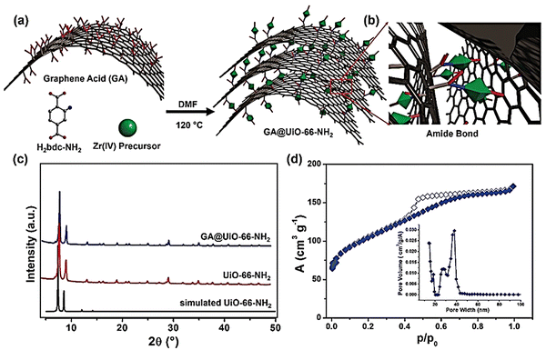 | ||
| Fig. 13 (a) Schematic illustration of the covalent assembly of GA and UiO-66-NH2 into GA@UiO-66-NH2 under solvothermal conditions via (b) amide bonds. Carbon, oxygen, and nitrogen are represented in grey, red, and blue, respectively. Hydrogens have been omitted for clarity. Green octahedra represent UiO-66-NH2 nanocrystals. (c) PXRD patterns of UiO-66-NH2 (black simulated pattern, red measured pattern) and GA@UiO-66-NH2 (blue pattern). (d) N2 adsorption isotherm of GA@UiO-66-NH2 measured at 77 K; filled symbols represent adsorption, empty symbols desorption. The inset shows the pore size distribution determined through the NLDFT method. Reproduced from ref. 162 with permission from WILEY-VCH, Copyright 2021. | ||
However, the HAADF TEM image of composite GA@UiO-66-NH2 exhibited a regular distribution of Zr, N, C, and O all over the sample. A three-electrode system was utilized to perform electrochemical experiments in 1 M Na2SO4. The shape of the CV curve is not fully rectangular, which suggests a charge contribution from the pseudocapacitive mechanism. This pseudocapacitive property may originate due to the stabilization of nitrogen-based functional amide groups on GA@UiO-66-NH2. At a current density of 2 A g−1, the obtained specific capacitance was 651 F g−1. Charge–discharge data collection at a very high current density demonstrated high rate performance. An asymmetric device was set up using Ti3C2Tx Mxene as a negative electrode and GA@UiO-66-NH2 as a positive electrode. This device showed high-energy battery-like and high-power capacitive properties with a power density of up to 16 kW kg−1 and an energy density of up to 73 W h kg−1. The devices exhibited 88% retention of their initial capacitance over 10![[thin space (1/6-em)]](https://www.rsc.org/images/entities/char_2009.gif) 000 cycles.
000 cycles.
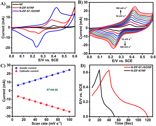 | ||
| Fig. 14 CV curves of bare NF, N-ZIF-67/NF, and N-ZIF-67·rGO/NF in 2 M KOH with a scan rate of 50 mV s−1 (A), CV curves of NZIF-67·rGO/NF in 2 M KOH at different scan rates (B), anodic and cathodic peak currents for N-ZIF-67·rGO/NF as a function of scan rate (C), and GCD curves of N-ZIF-67/NF and N-ZIF-67·rGO/NF in 2 M KOH at a current density of 20 mA (D). Reproduced from ref. 164 with permission from American Chemical Society, Copyright 2021. | ||
Here, the redox peaks and pseudocapacitive features of Co MOFs were associated with the reversible transition of Co3+ and Co2+. The following equations show the probable mechanism for the pseudocapacitance response:
| Co3O4 + OH− + H2O ↔ 3CoOOH + e− |
| CoOOH + OH− ↔ CoO2 + H2O + e− |
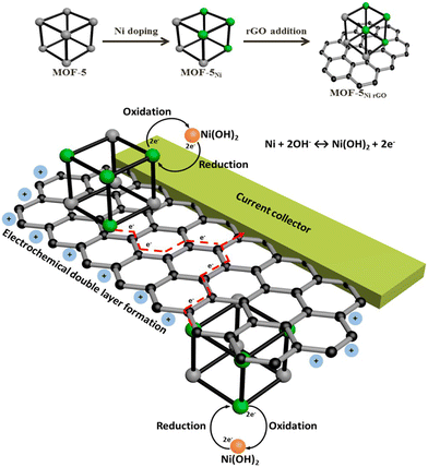 | ||
| Scheme 3 The concept for Ni doping and incorporating rGO to form a composite of rGO and Ni-doped MOF-5 and its use as an electrode material that harnesses both the electrochemical double layer performance of rGO and the reversible redox reactions of Ni metal centres with a synergy that facilitates effective and efficient charge transfer processes. Reproduced from ref. 165 with permission from American Chemical Society, Copyright 2015. | ||
MOF-5Ni50% and MOF-5Ni50%rGO50% were used for electrochemical performance. MOF-5Ni50% showed well-separated redox peaks, but for MOF-5Ni50%rGO50%, an anodic peak and a broad cathodic response were observed. The double-layer charging behaviour from the rGO nanosheets covers the faradaic region, resulting in a broad cathodic response. The capacitance value of MOF-5Ni50%rGO50% was found to be 758 F g−1 due to the synergistic interaction between rGO and MOF. The redox peak separation is about 122 mV, suggesting that the mechanism is the two-electron pathway. An efficient charge transfer occurred due to the combined effort of interconnected graphene nanosheets and distributed Ni centres in MOF-5.
| Cr(III) + OH− = Cr(II) |
| Mg2+ + 2OH− = Mg |
| Cr2+ + 2OH− = Cr |
Kim and co-workers prepared Ni–Co-MOF/GO via a one-pot solvothermal process (Fig. 15).168 Three samples were synthesized depending on the amount of graphene oxide, namely Ni–Co-MOF/GO1, Ni–Co-MOF/GO2, and Ni–Co-MOF/GO3.
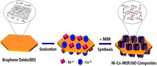 | ||
| Fig. 15 The scheme for the preparation process of Ni–Co-MOF/graphene oxide composites. Reproduced from ref. 168 with permission from Elsevier Ltd, Copyright 2019. | ||
Three-electrode configurations were used to study the electrochemical property in 6 M KOH. The values of specific capacitance obtained from the GCD data were 120 and 230.9 F g−1 for Ni–Co-MOF and Ni–Co-MOF/GO1, respectively, at a current density of 1 A g−1. Ni–Co-MOF/GO1, Ni–Co-MOF/GO2, and Ni–Co-MOF/GO3 demonstrated specific capacitances of 230.9, 447.2, and 341.8 F g−1 at a current density of 1 A g−1. The capacitive performance of the composite electrode can be associated with the synergistic effect of M-MOF, where Co partly takes the place of nickel and graphene oxide. Graphene oxide with a 2D layer structure produces a good amount of area for intercalation and deintercalation of OH−. The 3D structure of the composite gained by the synthesis of Ni–Co-MOF with the porous microstructure of the graphene oxide sheet able to assist the progress of high-speed charge transfer and the exposure of active sites to the electrolyte. This increases the capacitance value, where 99.6% reservation of capacitance value occurred for Ni–Co-MOF/GO2 after 3000 cycles.
Andikaey et al. synthesized another NiCo MOF via the solvothermal method using Co(NO3)2·6H2O, Ni(NO3)2·6H2O, and 1,4-benzene dicarboxylic acid.169 Liquid-phase exfoliated graphene (LEG) was prepared from a natural graphite shell using a green, cheap, and facile method. van der Waals and hydrophobic forces allow the adsorption of glucose derivatives on the LEG surface, and the connection of Ni and Co precursors is possible as the –OH and –COOH groups supply the active sites. This nanocomposite exhibited a 154.9 m2 g−1 surface area with an average pore diameter of 7.23 nm. The CV curve of the GM-LEG@NiCo-MOF electrode showed two redox peaks, which came from the redox reactions of Co(IV)/Co(III) and Ni(II)/Ni(III). The higher capacitance of GM-LEG@NiCo-MOF than NiCo-MOF or GM-LEG results from the synergistic effect of NiCo-MOF and GM-LEG in the nanocomposite. From the GCD curve, the obtained value of specific capacitance for GM-LEG@NiCo-MOF was 4077.3 F g−1. The good electrical conductivity of GM-LEG and the quasi-capacitive character of NiCo-MOF were the reasons behind the superb capacitance of GM-LEG@NiCo-MOF.
Mousavi and co-workers developed an Ni,Co-based MOF and reduced graphene oxide nanocomposite Ni/Co-MOF–rGO for use in supercapacitor applications.170 Electrochemical measurements were conducted in a 6 M KOH solution. Ni/Co-MOF–rGO exhibited a specific capacitance of 860 F g−1 at a current density of 1 A g−1, which is higher than that of Ni/Co-MOF, Ni-MOF, or Co-MOF. The authors suggested three reasons behind the higher capacitance value: (i) the higher surface area with a smaller particle size of the Co MOF favours capacitive charge storage; (ii) efficient synergistic effects among the Ni and Co metals are possible due to the homogeneous distribution of the MOF particles in the dual Ni/Co MOF composite, resulting in better capacitance performance; and (iii) synergistic effects among the MOF and rGO can act as a current collector at a nanoscale level and support the composite. The charge transfer resistance value from the EIS measurement for the Ni/Co-MOF–rGO electrode was the lowest (<5 Ω) among all the materials used in this study. A two-electrode asymmetric device was assembled for real utilization. The device delivered a specific energy of 72.8 W h kg−1 with a specific power of 850 W kg−1 at a current density of 1 A g−1. The asymmetric device showed 91.6% retention of capacitance value after carrying out 6000 GCD cycles. For practical application purposes, the authors tried to turn on a clock and light up blue, green, and red LEDs using this prototype device (Fig. 16).
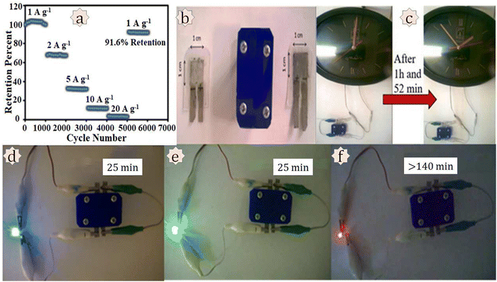 | ||
| Fig. 16 Investigation of practical applications. (a) Long-term cycling stability of the AC//Ni/CoMOF–rGO device at different current densities. Practical applications of the AC//Ni/Co-MOF–rGO device: (b) a simple laboratory prototype of the fabricated device; (c) turning on a clock for 1 h and 52 min; sequential lighting up of (d) blue, (e) green, and (f) red LEDs for a definite time. Reproduced from ref. 170 with permission from Elsevier Ltd, Copyright 2018. | ||
An Ni/Co-MOF/rGO composite with spherical particles decorated with rod-like morphology was synthesized by Kumaraguru et al. for electrochemical supercapacitor performance.171 Three-electrode configurations were utilized to perform electrochemical experiments on Ni/Co-MOF and Ni/Co-MOF/rGO in a 1 M KOH solution. Using the CV approach, the electrochemical activity of Ni/Co-MOF and Ni/Co-MOF/rGO composites was evaluated at various sweep rates varying from 5 to 100 mV s−1 (Fig. 17(A) and (B)). The presence of a redox peak in the CV curve indicated the pseudocapacitive nature of the Ni/Co-MOF and Ni/Co-MOF/rGO composites. At a scan rate of 5 mV s−1, Fig. 17(C) shows the CV profiles of composite electrodes made of Ni/Co-MOF and Ni/Co-MOF/rGO. Ni/Co-MOF and Ni/Co-MOF/rGO showed specific capacitances of 678 and 1162 F g−1 at a scan rate of 5 mV s−1. Specific capacitance is depicted against scan rate in Fig. 17(D), where there is an opposite correlation. The higher capacitance of Ni/Co-MOF/rGO in comparison to Ni/Co-MOF was explained by the following facts: (i) the rod-like morphology bearing high surface area helps by providing an electrical pathway for electron transport, facilitation of electron conduction, shortening of the diffusion path length of ions, and giving more pathways for ion diffusion; and (ii) the synergetic effect of rod-like Ni/Co-MOF and electronically conducting rGO furnish efficient and quick charge transfer features, boosting the overall electronic conductivity.
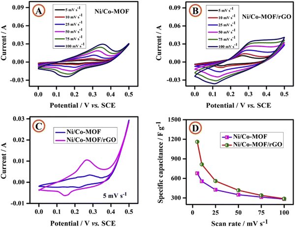 | ||
| Fig. 17 Cyclic voltammetric curves of (A) Ni/Co-MOF and (B) the Ni/Co-MOF/rGO composite at various scan rates; (C) cyclic voltammetric curves of Ni/Co-MOF and the Ni/CoMOF/rGO composite at a scan rate of 5 mV s−1 and (D) specific capacitance vs. scan rate. Reproduced from ref. 171 with permission from Elsevier Ltd, Copyright 2020. | ||
From the GCD data, the calculated specific capacitances of Ni/Co-MOF and Ni/CoMOF/rGO electrodes were 565 and 958 F g−1, respectively, at a current density of 1 A g−1. 109% conservation of capacitance occurred after performing 5000 cycles at a scan rate of 100 mV s−1. The higher stability was associated with two reasons: (i) enhancement in fast electron transfer over the Ni/Co-MOF rods occurs owing to the conductive network of rGO; and (ii) aggregation of the rod-like morphology of Ni/Co-MOF is prevented due to the presence of the rGO matrix, which provides ample surface area for electrochemical redox reactions.
Shi et al. fabricated flexible and highly conductive two-dimensional nickel cobalt MOFs/reduced graphene oxide hybrid films (2D/2D NiCo-MOFs/rGO) using a simple vacuum filtration method followed by calcination at different temperatures.172 The authors found that the suitable ratio of MOF and graphene oxide was 2![[thin space (1/6-em)]](https://www.rsc.org/images/entities/char_2009.gif) :
:![[thin space (1/6-em)]](https://www.rsc.org/images/entities/char_2009.gif) 1 as precursor materials for supercapacitor applications and denoted it as NCM/GO-2, as a higher content of NiCo-MOF resulted in the destruction of the hybrid film. Then NCM/GO-2 was treated at 200 °C, 300 °C, and 400 °C and named NCM/rGO-200, NCM/rGO-300, and NCM/rGO-400, respectively. The heat treatment process was performed to make ion diffusion feasible, resulting in the creation of active sites in the MOFs by removing the residual solvent present in them and reducing the graphene oxide to increase the conductivity of the composite material. PXRD, SEM, TEM, FTIR, Raman, BET, and XPS analyses were performed to characterize the composites. The supercapacitor performances of the synthesized materials were studied in a three-electrode arrangement using 2 M KOH as an electrolyte. The results showed that the NCM/rGO-300 hybrid film had a higher areal capacitance of 4.31 F cm−2 at 1 mA cm−2. The higher areal capacitance NCM/rGO-300 was due to the higher conductivity and greater active sites in the MOFs of the composite material. Furthermore, an asymmetric two-electrode set-up was fabricated using NCM/rGO-300 as cathode material and activated carbon as anode material for real application. The asymmetric device achieved a higher value of areal energy density of 199.4 μW h cm−2 at a power density of 801.9 μW cm−2. Also, the two-electrode assembly exhibited an outstanding cyclic stability of 92.51% after 5000 cycles.
1 as precursor materials for supercapacitor applications and denoted it as NCM/GO-2, as a higher content of NiCo-MOF resulted in the destruction of the hybrid film. Then NCM/GO-2 was treated at 200 °C, 300 °C, and 400 °C and named NCM/rGO-200, NCM/rGO-300, and NCM/rGO-400, respectively. The heat treatment process was performed to make ion diffusion feasible, resulting in the creation of active sites in the MOFs by removing the residual solvent present in them and reducing the graphene oxide to increase the conductivity of the composite material. PXRD, SEM, TEM, FTIR, Raman, BET, and XPS analyses were performed to characterize the composites. The supercapacitor performances of the synthesized materials were studied in a three-electrode arrangement using 2 M KOH as an electrolyte. The results showed that the NCM/rGO-300 hybrid film had a higher areal capacitance of 4.31 F cm−2 at 1 mA cm−2. The higher areal capacitance NCM/rGO-300 was due to the higher conductivity and greater active sites in the MOFs of the composite material. Furthermore, an asymmetric two-electrode set-up was fabricated using NCM/rGO-300 as cathode material and activated carbon as anode material for real application. The asymmetric device achieved a higher value of areal energy density of 199.4 μW h cm−2 at a power density of 801.9 μW cm−2. Also, the two-electrode assembly exhibited an outstanding cyclic stability of 92.51% after 5000 cycles.
![[thin space (1/6-em)]](https://www.rsc.org/images/entities/char_2009.gif) 000 cycles, suggesting the superior performance of the electrode towards energy storage devices.
000 cycles, suggesting the superior performance of the electrode towards energy storage devices.
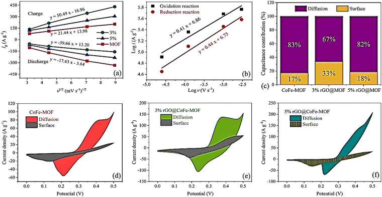 | ||
Fig. 18 (a) The curves of the peak current versus the square root of sweep rate (Randles–Sevcik plot). (b) The plots of log![[thin space (1/6-em)]](https://www.rsc.org/images/entities/char_2009.gif) i versus log i versus log![[thin space (1/6-em)]](https://www.rsc.org/images/entities/char_2009.gif) ν. (c) Capacitance contribution for three electrodes, the capacitive contribution of CV curves at 10 mV s−1 for (d) CoFe-MOF, (e) 3% rGO@CoFe-MOF, and (f) 5% rGO@CoFe-MOF. Reproduced from ref. 173 with permission from Elsevier Ltd, Copyright 2023. ν. (c) Capacitance contribution for three electrodes, the capacitive contribution of CV curves at 10 mV s−1 for (d) CoFe-MOF, (e) 3% rGO@CoFe-MOF, and (f) 5% rGO@CoFe-MOF. Reproduced from ref. 173 with permission from Elsevier Ltd, Copyright 2023. | ||
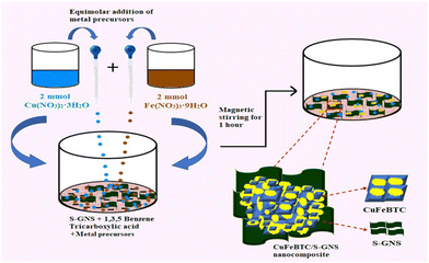 | ||
| Scheme 4 Schematic illustration of the synthesis procedure of CuFeBTC/S-GNS nanocomposite. Reproduced from ref. 175 with permission from Elsevier Ltd, Copyright 2019. | ||
The TEM study revealed that the surface of graphene was changed with the sulfur atoms. In CuFeBTC/S-GNS, the distinctive characteristics of CuBTC and S-GNS were finely displayed where the heavy CuFeBTC particles were routinely arranged on the surface of S-GNS. The BET-surface areas for the CuFeBTC/S-GNS composite and CuFeBTC were found to be 568.75 m2 g−1 and 313.54 m2 g−1, respectively, with large pore volumes of 0.52 cm3 g−1 and 0.24 cm3 g−1. The surface area of CuFeBTC increased upon the addition of S-GNS, which provides better electrochemical charge storage properties. The CuFeBTC/S-GNS composite in 1 M Na2SO4 exhibited a rectangular shape under the CV curve, indicating high charge storage ability. The synergy of S-GNS and CuFeBTC MOF proceeds with the EDLC charge storage mechanism from S-GNS and pseudocapacitance from the redox process in the MOF (Scheme 5). Cyclic voltammetry experiments were performed at different scan rates for CuFeBTC nanopowder and CuFeBTC/S-GNS nanocomposite electrodes. CuFeBTC showed two redox peaks even at a high scan rate, suggesting good reversibility in electrochemical performance and rate performance. However, in the case of CuFeBTC/S-GNS, the supercapacitor behaviour of the composite increased with increasing scan rate owing to the steep rise in specific current.
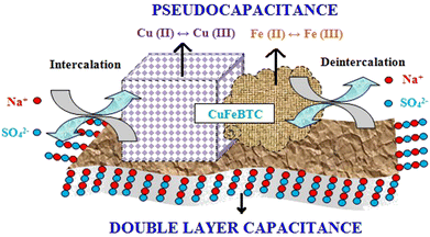 | ||
| Scheme 5 Pictorial representation of charge storage in the CuFeBTC/S-GNS nanocomposite. Reproduced from ref. 175 with permission from Elsevier Ltd, Copyright 2019. | ||
The addition of S-GNS to CuFeBTC provides maximum EDLC effect to pristine CuFeBTC, which improves its supercapacitor behaviour. From the GCD plot, the specific capacitance value was 1164.3 F g−1 at a current density of 0.5 A g−1 for CuFeBTC/S-GNS. The authors suggested some reasons behind the high specific capacitance of the hybrid composite: (i) instant contact between the CuFeBTC network and high-surface-area S-GNS sheets is possible due to the typical structure of CuFeBTC/S-GNS; (ii) the heterobimetallic structure of CuFeBTC with sufficient porosity provides high charge storage, and destruction of the heterobimetallic MOF is prevented due to the presence of S-GNS; (iii) the penetrated S-GNS sheets reveal discrete CuFeBTC particles and this connection increases the conductivity, ultimately providing efficient transportation of charge across the structure; and (iv) electrical double layer charge storage is possible with S-GNS through the adsorption of electrolyte ions on its surface. The heterobimetallic MOF gathered on the surface of S-GNS with a tunable porous structure provides high surface area and electronic conductivity. These are the reasons behind the good supercapacitance performance. An improvement in electrochemical kinetics is possible as the interconnected structure allows swift electron and electrolyte transport at the time of the charge–discharge process. This interconnected structure permits electrolyte transport and swift electrons during the charge–discharge process, enhancing the electrochemical kinetics. The cycle life of CuFeBTC and CuFeBTC/S-GNS electrodes was measured by collecting consecutive GCD cycles at 0.5 A g−1, where 90.2% and 79.4% retention of initial capacitance occurred after 4500 cycles for CuFeBTC/S-GNS and CuFeBTC, respectively. To apply CuFeBTC/S-GNS in a real application, a two-electrode symmetric supercapacitor device was assembled using CuFeBTC/S-GNS as cathode and anode.
A summary of supercapacitor performance using MOF–graphene composite is provided in Table 1.
| Composite | Electrolyte | Specific capacitance (F g−1) | Scan rate/current density | Energy density (W h kg−1) | Power density (W kg−1) | Ref. |
|---|---|---|---|---|---|---|
| ZIF-67/rGO | 0.2 M K3[Fe(CN)6] in 1 M Na2SO4 | 1453 | 4.5 A g−1 | 25.5 | 2700 | 141 |
| ZIF-67/GO-2 | 6 M KOH | 100.47 | 5 mV s−1 | — | — | 142 |
| CoMG5 | 6 M KOH | 549.96 | 10 mV s−1 | 8.10 | 850 | 143 |
| CoBTC/GNS | 1 M KOH | 608.2 | 0.25 A g−1 | 49.8 | 1025.8 | 144 |
| G@Ni-MOF | 6 M KOH | 1017 | 10 mV s−1 | 39.43 | 34.29 | 145 |
| Ni-MOF/rGO-300 | 6 M KOH | 954 | 1 A g−1 | 17.13 | 750 | 146 |
| GM-LEG@Ni-MOF | 3 M KOH | 987.6 | 0.5 A g−1 | 32.7 | 750 | 147 |
| Ni-MOF/rGO | 6 M KOH | 1154.4 | 0.66 A g−1 | 0.82 | 20 | 148 |
| Ni-BPDC/GO-3 | 6 M KOH | 630 | 1 A g−1 | 16.5 | 250 | 149 |
| IITKGP-20A-GO3 | 6 M KOH | ∼840 | 2 A g−1 | 30.7 | 388.5 | 150 |
| Ni-BTC@GO 2 | 3 M KOH | 1199 | 1 A g−1 | 40.89 | 800 | 151 |
| Ni-MOF–graphene nanocomposite | 2 M NaCl | 111.68 | 0.3 A g−1 | 14.68 | 291.82 | 152 |
| Cu-MOF/G | 6 M KOH | 482 | 10 mV s−1 | 34.5 | 1350 | 153 |
| HMRL-1/R | 1 M Na2SO4 | 366.6 | 1 A g−1 | 14.66 | 21![[thin space (1/6-em)]](https://www.rsc.org/images/entities/char_2009.gif) 100 100 |
154 |
| q-2D-MOF/rGO | 1 M H2SO4 | 292 | 1 A g−1 | — | — | 155 |
| MrGO | 1 M KCl | 208.9 | — | 31.2 | 656.4 | 156 |
| Cu-MOF/rGO (CR) | 1 M Na2SO4 | 867.09 | 1 A g−1 | 30.56 | 12![[thin space (1/6-em)]](https://www.rsc.org/images/entities/char_2009.gif) 000 000 |
157 |
| 10 wt% rGO and HKUST-1 | 0.5 M Na2SO4 | 385 | 1 A g−1 | 42 | 3100 | 158 |
| GAMOF(Fe3+) | 1 M H2SO4 | 353 | 20 A g−1 | 36 | 588 | 159 |
| Zn-MOF–rGO | 3 M KOH | 205 C g−1 | 1 A g−1 | 7.1 | 400 | 160 |
| ZIF-8/GO | 6 M KOH | 160 | 5 mV s−1 | — | — | 161 |
| GA@UiO-66-NH2 | 1 M Na2SO4 | 651 | 2 A g−1 | 73 | 16![[thin space (1/6-em)]](https://www.rsc.org/images/entities/char_2009.gif) 000 000 |
162 |
| MIL-53(Al)@rGO | 1 M KOH | 280 | 0.5 A g−1 | 6.66 | 200 | 163 |
| N-ZIF-67·rGO/NF | 2 M KOH | 962 | 20 mA cm−2 | — | — | 164 |
| MOF-5 Ni50%rGO50% | 1 M KOH | 758 | — | 37.8 | 226.7 | 165 |
| MIL-101(Cr,Mg)/rGO | 6 M KOH | 261.41 | 1 A g−1 | 4.65 | 7653 | 166 |
| NiCo-MOF/rGO-2 | — | 1553 | 1 A g−1 | 44 | 3168 | 167 |
| Ni–Co-MOF/GO2 | 6 M KOH | 447.2 | 1 A g−1 | — | — | 168 |
| GM-LEG@NiCo-MOF | Mixture of 3 M aqueous KOH and 0.1 M K4Fe(CN)6 | 4077.3 | 2.5 A g−1 | 76.3 | 2250 | 169 |
| Ni/Co-MOF–rGO | 6 M KOH | 860 | 1 A g−1 | 72.8 | 850 | 170 |
| Ni/Co-MOF/rGO | 1 M KOH | 1162 | 5 mV s−1 | — | — | 171 |
| 2D/2D NiCo-MOFs/rGO | 2 M KOH | 4.31 F cm−2 | 1 mA cm−2 | 199.4 μW h cm−2 | 801.9 μW cm−2 | 172 |
| rGO@CoFe-MOF | 3 M KOH | 2069.1 | 0.5 A g−1 | 75.8 | 700 | 173 |
| ZnCo-MOF/GS | 3 M KOH | 695 | 1 A g−1 | 108 | 5037 | 174 |
| CuFeBTC/S-GNS | 1 M Na2SO4 | 1164.3 | 0.5 A g−1 | 96.57 | 1595.12 | 175 |
4.4 Various Other MOF-based composites and their derivatives
For an improvement in the conductivity issue, several other MOF-based composites and their derivatives were prepared and utilized for supercapacitor purposes. In composites, synergistic effects between two interconnected materials can be employed to maximize the benefits of single materials or to get around their drawbacks.176 Thus, one may create hybrid electrodes for applications involving supercapacitors using the composite construction technique. The EDLC and pseudocapacitive characteristics of the relevant individual substances can be retained via hybrid electrodes. This hybrid approach contributes to the delivery of exceptional specific capacitance, a prolonged lifespan, good energy, and high power densities. Compared to pure MOFs, MOF derivatives not only substantially maintain their primary porous framework architecture but also display enhanced stability, a void distribution that is tunable, and sufficient electroactive locations where energy-related technology may be developed.177 A detailed review of MOF-MXene composites and their derivatives with respect to electrochemical applications has been provided by Pang and coworkers.177 The quick transfer of electrons and ions could be efficiently accelerated by the proposed hierarchical arrangement, conductive support, high active area, and enhanced interlayer spacing of MXene/MOF hybrids and their derivatives. Additionally, the interfacial contacts generated in the composites increased their chemical durability and reduced volume growth during the quick charge–discharge mechanism. Hybridization with MXene in the 3D porous structure has been studied for a high-performance asymmetric supercapacitor device using Ni-based MOF [Ni(Tdc)(Bpy)]n with a porous framework and good structural durability.178 Rapid ion transport was made possible by the incorporation of Ni-MOF since it considerably enhanced the interlamellar gap of MXene. A highly stable Ni-Bpy linear chain may be responsible for the improved cycling stability of MXene@Ni-MOF. Compared to the electrochemical performance of MXene, MXene + Ni-MOF, and pure MOF, MXene@Ni-MOF displayed noticeably increased electrochemical performance. The presence of a highly stable Ni-Bpy linear chain was responsible for the remarkable cyclic performance of the built ASC device, with 98% retention of specific capacitance after 5000 cycles. Hierarchical nickel phosphates-MXene (MXene/NPO) were made by phosphorylating an Ni-BDC/MXene composite in a KH2PO4 aqueous solution for electrode materials in supercapacitor applications.179 The electrode materials exhibited exceptional cycling stability, with 85% retention of capacity after 10![[thin space (1/6-em)]](https://www.rsc.org/images/entities/char_2009.gif) 000 cycles and a high specific capacity of 639 C g−1 at 0.5 A g−1. The nickel phosphate-derived in situ MOFs were decorated, strengthening the bonds between MXene and nickel phosphate and encouraging electron transport. Luo et al. prepared a Co3S4/Ti3C2Tx composite through the sulfidation of a cobalt-based ZIF-67/Ti3C2Tx composite in the presence of thioacetamide (TAA) under hydrothermal conditions.180 In a 3 M KOH solution, an electrode with Co3S4/Ti3C2Tx as its active substance had a very high specific capacitance of 602 F g−1 at a current density of 1 A g−1, which was 2.6 times greater than that of an electrode with ZIF-67/Ti3C2Tx and 4.5 times higher than that of electrodes with ZIF-67. At 10 A g−1, Co3S4/Ti3C2Tx exhibited 81.6% retention of capacitance, which was larger than those of ZIF-67 of 67.7% or ZIF-67/Ti3C2Tx of 75.8%. The authors suggested that the greater effectiveness of the Co3S4/Ti3C2Tx-based electrode can be attributed to (1) its greater reactivity and pseudocapacitance, which, when combined with (2) its substantial porosity, are very helpful for the quick insertion–extraction of OH− from the electrolyte. (3) The third component is a three-dimensional (3D) structure that offers simple conductive routes for effective transport of charges and electrolyte infiltration. (4) The final, but certainly not least reason is the existence of Ti3C2Tx, which offered stability and support to the composite and protected the entire structure from harm caused by the ongoing electrochemical processes between oxidation and reduction. The Co3S4/Ti3C2Tx-based electrode performed excellently in terms of rate thanks to every one of these features. MOF–carbon nanotube (CNT) composites have also been explored by many researchers.181 Ni-MOF was directly grown on the surface of CNTs by Wang and coworkers to create Ni-MOF@CNT.182 Ni-MOF@CNTs provided a specific capacitance of 1765 F g−1 at 0.5 A g−1 in 6 M KOH, which was 1.6 times the capacitance of 1080 F g−1 for pure Ni-MOF. Furthermore, 95% of the capacitance was present in Ni-MOF@CNT after 5000 charge–discharge cycles. This dominance is due to the synergistic interaction between Ni-MOF and CNTs. The porous structure of Ni MOF can facilitate the entrance of electrolytes, while CNT may substantially boost the conductivity of the entire composite capacitor. MOF–conductive polymer composites have also been applied for supercapacitor applications. Neisi et al. prepared PANI/Cu-MOF at room temperature to study its supercapacitor behaviour.183 In 6 M KOH electrolyte, with a scan rate of 5 mV s−1, the composite displayed pseudocapacitance behaviour, and its specific capacitance (734 F g−1) was larger than that of pure Cu-MOF of 558 F g−1. By supplying ion channels and electron transport pathways, polyaniline is thought to enhance the number of sites for activity in the redox procedure, enhancing the specific capacitance. So, creating Cu-MOF hybrids with polyaniline as the polymer that conducts electricity is a successful way to raise the specific capacitance and cycle life of Cu-MOF. An Ni3(NO3)2(OH)4@ZrMOF composite with a flower-like morphology was prepared by Tang and coworkers to study its supercapacitor performance.184 In 6 M KOH, Ni3(NO3)2(OH)4@ZrMOF displayed a higher specific capacitance of 992 F g−1 at a scan rate of 5 mV s−1 compared to 134 F g−1 for Zr-MOF and 753 F g−1 for Ni3(NO3)2(OH)4. After 3000 cycles, the Ni3(NO3)2(OH)4@ZrMOF electrode showed outstanding capacitance retention, suggesting good cycling stability. The large specific surface area of Zr-MOF, which maximizes Ni3(NO3)2(OH)4 dispersion on Zr-MOF, is credited for the high specific capacitance. Additionally, the porous structure of Zr-MOF offers ions easy paths to travel. Yao et al. prepared a K0.5Mn2O4@Mn-MOF-8 nanosheet array composite to perform a supercapacitor study.185 K0.5Mn2O4@Mn-MOF-8 exhibited a remarkable capacitance of 886.9 F g−1 at 1 A g −1 current density. The asymmetric device (ASC) comprised K0.5Mn2O4@Mn-MOF-8 and WO3, which had a potential window of 2 V and remarkable cycling stability. The authors suggested three reasons for the better performance of K0.5Mn2O4@Mn-MOF-8. First, by adding or removing the hydrated cations (K+) of K0.5Mn2O4, the conductivity of the electrode materials is improved, and the capacitance is increased. Also, the synergistic as well as annealing effect of various metals are the driving forces to enhance the electrochemical performance towards supercapacitor applications.186–188 In the electrochemical examination, the added crystal water supports a stable structure and inhibits the dissolution of manganese oxide. Second, K0.5Mn2O4 nanosheets with a vertical orientation and an interlayer spacing of 7.2 Å offer a large number of places for the storage of electrolyte ions and improve the efficiency of electrolyte uptake on the electrochemical interface. Third, the contact surface of the vertically co-oriented K0.5Mn2O4@Mn-MOF-8 nanosheets enhances the utilization rate of the electrode material and contains a large number of active sites.
000 cycles and a high specific capacity of 639 C g−1 at 0.5 A g−1. The nickel phosphate-derived in situ MOFs were decorated, strengthening the bonds between MXene and nickel phosphate and encouraging electron transport. Luo et al. prepared a Co3S4/Ti3C2Tx composite through the sulfidation of a cobalt-based ZIF-67/Ti3C2Tx composite in the presence of thioacetamide (TAA) under hydrothermal conditions.180 In a 3 M KOH solution, an electrode with Co3S4/Ti3C2Tx as its active substance had a very high specific capacitance of 602 F g−1 at a current density of 1 A g−1, which was 2.6 times greater than that of an electrode with ZIF-67/Ti3C2Tx and 4.5 times higher than that of electrodes with ZIF-67. At 10 A g−1, Co3S4/Ti3C2Tx exhibited 81.6% retention of capacitance, which was larger than those of ZIF-67 of 67.7% or ZIF-67/Ti3C2Tx of 75.8%. The authors suggested that the greater effectiveness of the Co3S4/Ti3C2Tx-based electrode can be attributed to (1) its greater reactivity and pseudocapacitance, which, when combined with (2) its substantial porosity, are very helpful for the quick insertion–extraction of OH− from the electrolyte. (3) The third component is a three-dimensional (3D) structure that offers simple conductive routes for effective transport of charges and electrolyte infiltration. (4) The final, but certainly not least reason is the existence of Ti3C2Tx, which offered stability and support to the composite and protected the entire structure from harm caused by the ongoing electrochemical processes between oxidation and reduction. The Co3S4/Ti3C2Tx-based electrode performed excellently in terms of rate thanks to every one of these features. MOF–carbon nanotube (CNT) composites have also been explored by many researchers.181 Ni-MOF was directly grown on the surface of CNTs by Wang and coworkers to create Ni-MOF@CNT.182 Ni-MOF@CNTs provided a specific capacitance of 1765 F g−1 at 0.5 A g−1 in 6 M KOH, which was 1.6 times the capacitance of 1080 F g−1 for pure Ni-MOF. Furthermore, 95% of the capacitance was present in Ni-MOF@CNT after 5000 charge–discharge cycles. This dominance is due to the synergistic interaction between Ni-MOF and CNTs. The porous structure of Ni MOF can facilitate the entrance of electrolytes, while CNT may substantially boost the conductivity of the entire composite capacitor. MOF–conductive polymer composites have also been applied for supercapacitor applications. Neisi et al. prepared PANI/Cu-MOF at room temperature to study its supercapacitor behaviour.183 In 6 M KOH electrolyte, with a scan rate of 5 mV s−1, the composite displayed pseudocapacitance behaviour, and its specific capacitance (734 F g−1) was larger than that of pure Cu-MOF of 558 F g−1. By supplying ion channels and electron transport pathways, polyaniline is thought to enhance the number of sites for activity in the redox procedure, enhancing the specific capacitance. So, creating Cu-MOF hybrids with polyaniline as the polymer that conducts electricity is a successful way to raise the specific capacitance and cycle life of Cu-MOF. An Ni3(NO3)2(OH)4@ZrMOF composite with a flower-like morphology was prepared by Tang and coworkers to study its supercapacitor performance.184 In 6 M KOH, Ni3(NO3)2(OH)4@ZrMOF displayed a higher specific capacitance of 992 F g−1 at a scan rate of 5 mV s−1 compared to 134 F g−1 for Zr-MOF and 753 F g−1 for Ni3(NO3)2(OH)4. After 3000 cycles, the Ni3(NO3)2(OH)4@ZrMOF electrode showed outstanding capacitance retention, suggesting good cycling stability. The large specific surface area of Zr-MOF, which maximizes Ni3(NO3)2(OH)4 dispersion on Zr-MOF, is credited for the high specific capacitance. Additionally, the porous structure of Zr-MOF offers ions easy paths to travel. Yao et al. prepared a K0.5Mn2O4@Mn-MOF-8 nanosheet array composite to perform a supercapacitor study.185 K0.5Mn2O4@Mn-MOF-8 exhibited a remarkable capacitance of 886.9 F g−1 at 1 A g −1 current density. The asymmetric device (ASC) comprised K0.5Mn2O4@Mn-MOF-8 and WO3, which had a potential window of 2 V and remarkable cycling stability. The authors suggested three reasons for the better performance of K0.5Mn2O4@Mn-MOF-8. First, by adding or removing the hydrated cations (K+) of K0.5Mn2O4, the conductivity of the electrode materials is improved, and the capacitance is increased. Also, the synergistic as well as annealing effect of various metals are the driving forces to enhance the electrochemical performance towards supercapacitor applications.186–188 In the electrochemical examination, the added crystal water supports a stable structure and inhibits the dissolution of manganese oxide. Second, K0.5Mn2O4 nanosheets with a vertical orientation and an interlayer spacing of 7.2 Å offer a large number of places for the storage of electrolyte ions and improve the efficiency of electrolyte uptake on the electrochemical interface. Third, the contact surface of the vertically co-oriented K0.5Mn2O4@Mn-MOF-8 nanosheets enhances the utilization rate of the electrode material and contains a large number of active sites.
5 Conclusions and future perspectives
In this review article, we have discussed the synthesis of different kinds of MOF–graphene composites and explored them in supercapacitor applications. Different types of transition-metal-based MOFs have been discussed with MOF–graphene composites in the field of supercapacitor application with their working principles. Recently, MOFs have been suffering from conductivity issues in their pristine form, so this limitation will be improved through the development of MOF–graphene composites. The mechanisms of supercapacitor behaviour using different metal-based MOF–graphene composites have also been addressed. The benefit of using a MOF–graphene composite compared to a pure MOF has been well explained. The exploration, emerging applications, key challenges, and future perspectives of MOF–graphene composites have been demonstrated in Fig. 19.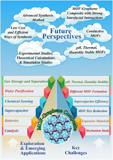 | ||
| Fig. 19 The exploration, emerging applications, key challenges, and future perspective of MOF–graphene composites. | ||
Despite significant advances in the research and development of MOF–graphene composite-based supercapacitor electrode materials, there are still a number of obstacles to be overcome before supercapacitors based on this technology may be commercialized with these resources. The following are the difficulties:
(a) For exceptionally well-suited applications, it is crucial to reduce the size of MOFs on graphene in order to provide additional active regions for effective electrochemical reactions while avoiding agglomeration.
(b) Currently, there are just a few reported varieties of MOFs, mostly from the ZIF, MIL, UiO, and HKUST-1 series. More optimized MOFs and their graphene composites can be produced by carefully controlling their makeup and composition.
(c) In addition to significantly impacting charge transfer, the strength of the surface among MOFs and graphene also influences ion adsorption energy and diffusion kinetics, which in turn affects supercapacitor efficiency.
(d) MOF–graphene composites need to work in severe environments and function at their peak under particular circumstances (pH, temperature, humidity, etc.) for supercapacitor applications; their potential for advancement is somewhat constrained.
(e) Despite the fact that the materials used in electrodes made of MOF–graphene composites exhibit favourable properties, it is unclear exactly how these structural modifications and their effects on the electrochemical process work. It is essential to understand the electrochemical activities for designing high-performance electrode materials.
(f) The biggest issue with the broad acceptance of MOF–graphene composite electrodes is expense. Using expensive ligands, solvents, and laborious preparation methods has made massive production difficult in several ways.
Even though MOF–graphene composites face the aforementioned difficulties, the following modifications could be made to address these problems and enhance the supercapacitor performance of MOF–graphene composites.
(a) To create these incredibly small-sized MOFs, a novel and efficient method of synthesis must be developed.
(b) Additional MOF-based functional materials, like conductive MOFs, may be advantageous for electrochemical applications. Besides that, certain MOFs with excellent conductivity, chemical, thermal, and mechanical stability may be used in combination with graphene to create composites.
(c) Developing materials that use MOF–graphene composites with strong interfacial interactions thus becomes crucial for improving supercapacitor efficiency.
(d) In this respect, MOF–graphene composites still have opportunities for advancement. By using highly charged metal ions with oxygen donor sites of carboxylate ligands, a viable dual-ligand method can be constructed to improve building unit connections, enhance the framework hydrophobicity, and increase the rigidity of ligand-stable MOFs. Besides that, post-synthetic modifications (PSMs) could be undertaken to substitute the labile components with stable ones, increasing the stability of the framework.
(e) Extensive studies are required using experimental measurements, theoretical calculations, and simulation studies with the objective of learning more about the electrochemical mechanism of a supercapacitor. Furthermore, sophisticated characterization tools are also necessary.
(f) It is vitally necessary to develop innovative kinds of synthetic techniques in order to streamline the process and improve the uniformity of the composites that are produced. Large-scale manufacturing of MOFs and MOF–graphene composites could be made feasible at a relatively low cost due to the discovery of a range of straightforward and efficient methods of synthesis, like the one-pot solvent approach.
In conclusion, MOF–graphene composite materials have the potential for the extension of the usage of MOF-based materials despite the fact that there remain some obstacles to be overcome. We think that the information presented in this review will be useful for gaining an insight into how MOF–graphene composites are being used as potential materials in the area of supercapacitors and will serve as a useful resource for further investigation.
Abbreviations
| ZIF | Zeolitic imidazolate framework |
| G | Graphene |
| MIL | Materials Institute Lavoisier |
| UiO | Universitetet i Oslo |
Conflicts of interest
There are no conflicts to declare.Acknowledgements
D. K. S. acknowledges NALCO for the financial support. B. K. J. acknowledges NALCO (SSP 422) BRNS, Mumbai, India (No-2013/37P/67/BRNS), MNRE, New Delhi, India (No-102/87/2011-NT), and CSIR, New Delhi, India (HCP-42, OLP-48, OLP-95) for the financial support. P. B. thanks to DST-SERB, India, for Ramanujan fellowship (RJF/2020/000049) for the financial support.References
- X. Mu, H. Pan, P. He and H. Zhou, Adv. Mater., 2020, 32, 1903790 CrossRef CAS PubMed.
- S. Liu, L. Kang and S. C. Jun, Adv. Mater., 2021, 33, 2004689 CrossRef CAS PubMed.
- Y. Cao, J. Liang, X. Li, L. Yue, Q. Liu, S. Lu, A. M. Asiri, J. Hu, Y. Luo and X. Sun, Chem. Commun., 2021, 57, 2343 RSC.
- S. Zheng, H. Xue and H. Pang, Coord. Chem. Rev., 2018, 373, 2 CrossRef CAS.
- D. P. Dubal, P. Gomez-Romero, B. R. Sankapal and R. Holze, Nano Energy, 2015, 11, 377 CrossRef CAS.
- D. P. Dubal, J. G. Kim, Y. Kim, R. Holze, C. D. Lokhande and W. B. Kim, Energy Technol., 2014, 2, 325 CrossRef.
- A. Agarwal and B. R. Sankapal, J. Mater. Chem. A, 2021, 9, 20241 RSC.
- S. Liang, H. Wang, Y. Li, H. Qin, Z. Luo, B. Huang, X. Zhao, C. Zhao and L. Chen, Sustainable Energy Fuels, 2020, 4, 3825 RSC.
- T. Guo, D. Zhou, L. Pang, S. Sun, T. Zhou and J. Su, Small, 2022, 18, 2106360 CrossRef CAS PubMed.
- C. Zhong, Y. Deng, W. Hu, J. Qiao, L. Zhang and J. Zhang, Chem. Soc. Rev., 2015, 44, 7484 RSC.
- L. Wang, Y. Han, X. Feng, J. Zhou, P. Qi and B. Wang, Coord. Chem. Rev., 2016, 307, 361 CrossRef CAS.
- M. Rajkumar, C.-T. Hsu, T.-H. Wu, M.-G. Chen and C.-C. Hu, Prog. Nat. Sci.: Mater. Int., 2015, 25, 527 CrossRef CAS.
- I. Hussain, C. Lamiel, M. Ahmad, Y. Chen, S. Shuang, M. S. Javed, Y. Yang and K. Zhang, J. Energy Storage, 2021, 44, 103405 CrossRef.
- Y. Zeng, M. Yu, Y. Meng, P. Fang, X. Lu and Y. Tong, Adv. Energy Mater., 2016, 6, 1601053 CrossRef.
- S. Liu, L. Kang, J. Henzie, J. Zhang, J. Ha, M. A. Amin, M. S. A. Hossain, S. C. Jun and Y. Yamauchi, ACS Nano, 2021, 15, 18931 CrossRef CAS PubMed.
- Z. Yang, J. Tian, Z. Yin, C. Cui, W. Qian and F. Wei, Carbon, 2019, 141, 467 CrossRef CAS.
- S. Kumar, G. Saeed, L. Zhu, K. N. Hui, N. H. Kim and J. H. Lee, Chem. Eng. J., 2021, 403, 126352 CrossRef CAS.
- Z. Yu, L. Tetard, L. Zhai and J. Thomas, Energy Environ. Sci., 2015, 8, 702 RSC.
- J. Huang, K. Yuan and Y. Chen, Adv. Funct. Mater., 2022, 32, 2108107 CrossRef CAS.
- J. Yan, Q. Wang, T. Wei and Z. Fan, Adv. Energy Mater., 2014, 4, 1300816 CrossRef.
- A. Velasco, Y. K. Ryu, A. Boscá, A. Ladrón-de-Guevara, E. Hunt, J. Zuo, J. Pedrós, F. Calle and J. Martinez, Sustainable Energy Fuels, 2021, 5, 1235 RSC.
- C. Yuan, L. Yang, L. Hou, L. Shen, X. Zhang and X. W. Lou, Energy Environ. Sci., 2012, 5, 7883 RSC.
- Y. Zhu, S. Murali, M. D. Stoller, K. J. Ganesh, W. Cai, P. J. Ferreira, A. Pirkle, R. M. Wallace, K. A. Cychosz, M. Thommes, D. Su, E. A. Stach and R. S. Ruoff, Science, 2011, 332, 1537 CrossRef CAS PubMed.
- M. Winter and R. J. Brodd, Chem. Rev., 2004, 104, 4245 CrossRef CAS PubMed.
- X. Yang, C. Cheng, Y. Wang, L. Qiu and D. Li, Science, 2013, 341, 534 CrossRef CAS PubMed.
- L. L. Zhang and X. S. Zhao, Chem. Soc. Rev., 2009, 38, 2520 RSC.
- P.-C. Chen, G. Shen, Y. Shi, H. Chen and C. Zhou, ACS Nano, 2010, 4, 4403 CrossRef CAS PubMed.
- A. Burke, J. Power Sources, 2000, 91, 37 CrossRef CAS.
- S. Liu, L. Kang, J. Hu, E. Jung, J. Henzie, A. Alowasheeir, J. Zhang, L. Miao, Y. Yamauchi and S. C. Jun, Small, 2022, 18, 2104507 CrossRef CAS PubMed.
- J. Yang, P. Xiong, C. Zheng, H. Qiu and M. Wei, J. Mater. Chem. A, 2014, 2, 16640 RSC.
- A. S. Aricò, P. Bruce, B. Scrosati, J.-M. Tarascon and W. van Schalkwijk, Nat. Mater., 2005, 4, 366 CrossRef PubMed.
- V. Subramanian, H. Zhu, R. Vajtai, P. M. Ajayan and B. Wei, J. Phys. Chem. B, 2005, 109, 20207 CrossRef CAS PubMed.
- S. Sarangapani, B. V. Tilak and C. P. Chen, J. Electrochem. Soc., 1996, 143, 3791 CrossRef CAS.
- S. Sanati, R. Abazari, A. Morsali, A. M. Kirillov, P. C. Junk and J. Wang, Inorg. Chem., 2019, 58, 16100 CrossRef CAS PubMed.
- R. Zeng, Z. Li, L. Li, Y. Li, J. Huang, Y. Xiao, K. Yuan and Y. Chen, ACS Sustainable Chem. Eng., 2019, 7, 11540 CrossRef CAS.
- M. Yi, C. Zhang, C. Cao, C. Xu, B. Sa, D. Cai and H. Zhan, Inorg. Chem., 2019, 58, 3916 CrossRef CAS PubMed.
- A. Mohanty, D. Jaihindh, Y.-P. Fu, S. P. Senanayak, L. S. Mende and A. Ramadoss, J. Power Sources, 2021, 488, 229444 CrossRef CAS.
- Z. Sun, K. Qu, Y. You, Z. Huang, S. Liu, J. Li, Q. Hu and Z. Guo, J. Mater. Chem. A, 2021, 9, 7278 RSC.
- N. H. N. Azman, M. S. M. Mat Nazir, L. H. Ngee and Y. Sulaiman, Int. J. Energy Res., 2018, 42, 2104 CrossRef CAS.
- Y. Huang, H. Li, Z. Wang, M. Zhu, Z. Pei, Q. Xue, Y. Huang and C. Zhi, Nano Energy, 2016, 22, 422 CrossRef CAS.
- M. Sajjad, M. I. Khan, F. Cheng and W. Lu, J. Energy Storage, 2021, 40, 102729 CrossRef.
- Q. Yang, Z. Li, R. Zhang, L. Zhou, M. Shao and M. Wei, Nano Energy, 2017, 41, 408 CrossRef CAS.
- D. Pech, M. Brunet, H. Durou, P. Huang, V. Mochalin, Y. Gogotsi, P.-L. Taberna and P. Simon, Nat. Nanotechnol., 2010, 5, 651 CrossRef CAS PubMed.
- X. Chu, F. Meng, T. Deng and W. Zhang, Nanoscale, 2021, 13, 5570 RSC.
- S. Liu, L. Kang, J. Zhang, S. C. Jun and Y. Yamauchi, NPG Asia Mater., 2023, 15, 9 CrossRef CAS.
- S. Liu, D. Ni, H.-F. Li, K. N. Hui, C.-Y. Ouyang and S. C. Jun, J. Mater. Chem. A, 2018, 6, 10674 RSC.
- S. Liu, L. Kang, J. Zhang, E. Jung, S. Lee and S. C. Jun, Energy Storage Mater., 2020, 32, 167 CrossRef.
- M. Kandasamy, S. Sahoo, S. K. Nayak, B. Chakraborty and C. S. Rout, J. Mater. Chem. A, 2021, 9, 17643 RSC.
- Y. Liu, Q. Wu, L. Liu, P. Manasa, L. Kang and F. Ran, J. Mater. Chem. A, 2020, 8, 8218 RSC.
- N. Kumar, L. Pradhan and B. K. Jena, Wiley Interdiscip. Rev.: Energy Environ., 2022, 11, e415 CAS.
- S. Kamila, P. Mane, R. I. Mohanty, B. Chakraborty and B. K. Jena, Electrochim. Acta, 2021, 399, 139357 CrossRef CAS.
- B. Mohanty, L. Giri and B. K. Jena, Energy Fuels, 2021, 35, 14304 CrossRef CAS.
- S. K. Das, S. Kamila, B. Satpati, M. Kandasamy, B. Chakraborty, S. Basu and B. K. Jena, J. Power Sources, 2020, 471, 228465 CrossRef CAS.
- S. Kamila, M. Kandasamy, B. Chakraborty and B. K. Jena, New J. Chem., 2020, 44, 1418 RSC.
- S. Kamila, B. Chakraborty, S. Basu and B. K. Jena, J. Phys. Chem. C, 2019, 123, 24280 CrossRef CAS.
- S. Kamila, B. K. Jena and S. Basu, Energy Storage, 2021, p. 119 DOI:10.1002/9781119555599.ch4.
- L. L. Zhang, R. Zhou and X. S. Zhao, J. Mater. Chem., 2010, 20, 5983 RSC.
- Y. B. Tan and J.-M. Lee, J. Mater. Chem. A, 2013, 1, 14814 RSC.
- C. Pei, M. S. Choi, X. Yu, H. Xue, B. Y. Xia and H. S. Park, J. Mater. Chem. A, 2021, 9, 8832 RSC.
- Z. Bi, Q. Kong, Y. Cao, G. Sun, F. Su, X. Wei, X. Li, A. Ahmad, L. Xie and C.-M. Chen, J. Mater. Chem. A, 2019, 7, 16028 RSC.
- D. Ghosh, A. Pal, D. K. Singha, S. Ghosh, O. I. Lebedev, M. M. Seikh and P. Mahata, ACS Appl. Nano Mater., 2020, 3, 10105 CrossRef CAS.
- L. Li, F. Lu, R. Xue, B. Ma, Q. Li, N. Wu, H. Liu, W. Yao, H. Guo and W. Yang, ACS Appl. Mater. Interfaces, 2019, 11, 26355 CrossRef CAS PubMed.
- A. Halder, M. Ghosh, A. Khayum M, S. Bera, M. Addicoat, H. S. Sasmal, S. Karak, S. Kurungot and R. Banerjee, J. Am. Chem. Soc., 2018, 140, 10941 CrossRef CAS PubMed.
- L. Pradhan, B. Nayak, A. Mukherjee, S. Basu, P. Bhanja and B. K. Jena, ACS Appl. Energy Mater., 2023, 6, 3347 CrossRef CAS.
- S. K. Das, L. Pradhan, B. K. Jena and S. Basu, Carbon, 2023, 201, 49 CrossRef CAS.
- A. K. Samantara, S. Chandra Sahu, A. Ghosh and B. K. Jena, J. Mater. Chem. A, 2015, 3, 16961 RSC.
- O. M. Yaghi and H. Li, J. Am. Chem. Soc., 1995, 117, 10401 CrossRef CAS.
- H. Li, M. Eddaoudi, M. O’Keeffe and M. Yaghi, Nature, 1999, 402, 276 CrossRef CAS.
- M. Li, D. Li, M. O’Keeffe and O. M. Yaghi, Chem. Rev., 2014, 114, 1343 CrossRef CAS PubMed.
- M. O’Keeffe and O. M. Yaghi, Chem. Rev., 2012, 112, 675 CrossRef PubMed.
- T. R. Cook, Y.-R. Zheng and P. J. Stang, Chem. Rev., 2013, 113, 734 CrossRef CAS PubMed.
- T. Chen, F. Wang, S. Cao, Y. Bai, S. Zheng, W. Li, S. Zhang, S.-X. Hu and H. Pang, Adv. Mater., 2022, 34, 2201779 CrossRef CAS PubMed.
- D. K. Singha, P. Majee, S. K. Mondal and P. Mahata, RSC Adv., 2015, 5, 102076 RSC.
- B. Xu, H. Zhang, H. Mei and D. Sun, Coord. Chem. Rev., 2020, 420, 213438 CrossRef CAS.
- Y. Zhao, J. Liu, M. Horn, N. Motta, M. Hu and Y. Li, Sci. China Mater., 2018, 61, 159 CrossRef CAS.
- H. Zhou, G. Zhu, S. Dong, P. Liu, Y. Lu, Z. Zhou, S. Cao, Y. Zhang and H. Pang, Adv. Mater., 2023, 35, 2211523 CrossRef CAS PubMed.
- C. Liu, Y. Bai, W. Li, F. Yang, G. Zhang and H. Pang, Angew. Chem., Int. Ed., 2022, 61, e202116282 CrossRef CAS PubMed.
- Y. Zheng, S. Zheng, H. Xue and H. Pang, Adv. Funct. Mater., 2018, 28, 1804950 CrossRef.
- H.-j Qu, L.-j Huang, Z.-y Han, Y.-x Wang, Z.-j Zhang, Y. Wang, Q.-r Chang, N. Wei, M. J. Kipper and J.-g Tang, J. Porous Mater., 2021, 28, 1837 CrossRef CAS.
- Z. Wang, J. Huang, J. Mao, Q. Guo, Z. Chen and Y. Lai, J. Mater. Chem. A, 2020, 8, 2934 RSC.
- X. Zhang, S. Zhang, Y. Tang, X. Huang and H. Pang, Composites, Part B, 2022, 230, 109532 CrossRef CAS.
- K. Jayaramulu, S. Mukherjee, D. M. Morales, D. P. Dubal, A. K. Nanjundan, A. Schneemann, J. Masa, S. Kment, W. Schuhmann, M. Otyepka, R. Zbořil and R. A. Fischer, Chem. Rev., 2022, 122, 17241 CrossRef CAS PubMed.
- Y. Ren and Y. Xu, Chem. Commun., 2023, 59, 6475 RSC.
- V. Kumari, P. Pal Singh and S. Kaushal, Polyhedron, 2022, 214, 115645 CrossRef CAS.
- L. Liu, Z. Niu and J. Chen, Chem. Soc. Rev., 2016, 45, 4340 RSC.
- A. G. Pandolfo and A. F. Hollenkamp, J. Power Sources, 2006, 157, 11 CrossRef CAS.
- P. Sharma and T. S. Bhatti, Energy Convers. Manage., 2010, 51, 2901 CrossRef CAS.
- Y. Bai, C. Liu, T. Chen, W. Li, S. Zheng, Y. Pi, Y. Luo and H. Pang, Angew. Chem., Int. Ed., 2021, 60, 25318 CrossRef CAS PubMed.
- Q. Ke and J. Wang, J. Materiomics, 2016, 2, 37 CrossRef.
- W. Shi, J. Zhu, D. H. Sim, Y. Y. Tay, Z. Lu, X. Zhang, Y. Sharma, M. Srinivasan, H. Zhang, H. H. Hng and Q. Yan, J. Mater. Chem., 2011, 21, 3422 RSC.
- M. Lu, F. Beguin and E. Frackowiak, Supercapacitors: Materials, Systems, and Applications, Wiley, 2013 Search PubMed.
- M. S. Halper and J. C. Ellenbogen, Supercapacitors: A Brief Overview, The MITRE Corporation, McLean, 2006 Search PubMed.
- B. Garai, A. Mallick and R. Banerjee, Chem. Sci., 2016, 7, 2195 RSC.
- M. S. Deenadayalan, N. Sharma, P. K. Verma and C. M. Nagaraja, Inorg. Chem., 2016, 55, 5320 CrossRef CAS PubMed.
- H. Kim, S. Yang, S. R. Rao, S. Narayanan, E. A. Kapustin, H. Furukawa, A. S. Umans, O. M. Yaghi and E. N. Wang, Science, 2017, 356, 430 CrossRef CAS PubMed.
- P. Mahata, S. Natarajan, P. Panissod and M. Drillon, J. Am. Chem. Soc., 2009, 131, 10140 CrossRef CAS PubMed.
- P. Ramaswamy, N. E. Wong and G. K. H. Shimizu, Chem. Soc. Rev., 2014, 43, 5913 RSC.
- P. Ji, K. Manna, Z. Lin, A. Urban, F. X. Greene, G. Lan and W. Lin, J. Am. Chem. Soc., 2016, 138, 12234 CrossRef CAS PubMed.
- C. He, D. Liu and W. Lin, Chem. Rev., 2015, 115, 11079 CrossRef CAS PubMed.
- L. J. Murray, M. Dinca and J. R. Long, Chem. Soc. Rev., 2009, 38, 1294 RSC.
- J.-R. Li, R. J. Kuppler and H.-C. Zhou, Chem. Soc. Rev., 2009, 38, 1477 RSC.
- R. Banerjee, A. Phan, B. Wang, C. Knobler, H. Furukawa, M. O'Keeffe and O. M. Yaghi, Science, 2008, 319, 939 CrossRef CAS PubMed.
- D.-X. Xue, Y. Belmabkhout, O. Shekhah, H. Jiang, K. Adil, A. J. Cairns and M. Eddaoudi, J. Am. Chem. Soc., 2015, 137, 5034 CrossRef CAS PubMed.
- D. K. Singha, P. Majee, S. Mandal, S. K. Mondal and P. Mahata, Inorg. Chem., 2018, 57, 12155 CrossRef CAS PubMed.
- D. K. Singha, P. Majee, S. Hui, S. K. Mondal and P. Mahata, Dalton Trans., 2020, 49, 829 RSC.
- P. Daga, S. Sarkar, P. Majee, D. K. Singha, S. Hui, P. Mahata and S. K. Mondal, Mater. Adv., 2021, 2, 985 RSC.
- P. Majee, P. Daga, D. K. Singha, D. Saha, P. Mahata and S. K. Mondal, J. Photochem. Photobiol., A, 2020, 402, 112830 CrossRef CAS.
- Y. Ban, Y. Li, X. Liu, Y. Peng and W. Yang, Microporous Mesoporous Mater., 2013, 173, 29 CrossRef CAS.
- N. Stock and S. Biswas, Chem. Rev., 2012, 112, 933 CrossRef CAS PubMed.
- P. Majee, D. K. Singha, P. Daga, S. Hui, P. Mahata and S. K. Mondal, CrystEngComm, 2021, 23, 4160 RSC.
- S. Henke, A. Schneemann, S. Kapoor, R. Winter and R. A. Fischer, J. Mater. Chem., 2012, 22, 909 RSC.
- Y. Sun and H.-C. Zhou, Sci. Technol. Adv. Mater., 2015, 16, 054202 CrossRef PubMed.
- M. Klimakow, P. Klobes, A. F. Thünemann, K. Rademann and F. Emmerling, Chem. Mater., 2010, 22, 5216 CrossRef CAS.
- B. Szczęśniak, S. Borysiuk, J. Choma and M. Jaroniec, Mater. Horiz., 2020, 7, 1457 RSC.
- N. K. Singh, M. Hardi and V. P. Balema, Chem. Commun., 2013, 49, 972 RSC.
- D. Chen, J. Zhao, P. Zhang and S. Dai, Polyhedron, 2019, 162, 59 CrossRef CAS.
- A. Martinez Joaristi, J. Juan-Alcañiz, P. Serra-Crespo, F. Kapteijn and J. Gascon, Cryst. Growth Des., 2012, 12, 3489 CrossRef CAS.
- S. Khazalpour, V. Safarifard, A. Morsali and D. Nematollahi, RSC Adv., 2015, 5, 36547 RSC.
- H. Ren and T. Wei, ChemElectroChem, 2022, 9, e202200196 CrossRef CAS.
- H. Al-Kutubi, J. Gascon, E. J. R. Sudhölter and L. Rassaei, ChemElectroChem, 2015, 2, 462 CrossRef CAS.
- W.-J. Son, J. Kim, J. Kim and W.-S. Ahn, Chem. Commun., 2008, 6336, 10.1039/B814740J.
- K. Yu, Y.-R. Lee, J. Y. Seo, K.-Y. Baek, Y.-M. Chung and W.-S. Ahn, Microporous Mesoporous Mater., 2021, 316, 110985 CrossRef CAS.
- T. Wiwasuku, J. Othong, J. Boonmak, V. Ervithayasuporn and S. Youngme, Dalton Trans., 2020, 49, 10240 RSC.
- J. H. Lee, Y. Ahn and S.-Y. Kwak, ACS Omega, 2022, 7, 23213 CrossRef CAS PubMed.
- J. Klinowski, F. A. Almeida Paz, P. Silva and J. Rocha, Dalton Trans., 2011, 40, 321 RSC.
- M. Taddei, P. V. Dau, S. M. Cohen, M. Ranocchiari, J. A. van Bokhoven, F. Costantino, S. Sabatini and R. Vivani, Dalton Trans., 2015, 44, 14019 RSC.
- R. Babu, R. Roshan, A. C. Kathalikkattil, D. W. Kim and D.-W. Park, ACS Appl. Mater. Interfaces, 2016, 8, 33723 CrossRef CAS PubMed.
- Z.-J. Lin, Z. Yang, T.-F. Liu, Y.-B. Huang and R. Cao, Inorg. Chem., 2012, 51, 1813 CrossRef CAS PubMed.
- S. Parshamoni and S. Konar, CrystEngComm, 2016, 18, 4395 RSC.
- K. Tomar, R. Rajak, S. Sanda and S. Konar, Cryst. Growth Des., 2015, 15, 2732 CrossRef CAS.
- A. Halder, A. Maiti, S. Dinda, B. Bhattacharya and D. Ghoshal, Cryst. Growth Des., 2021, 21, 6110 CrossRef CAS.
- G. Pahari, S. Ghosh, A. Halder and D. Ghoshal, Cryst. Growth Des., 2021, 21, 2633 CrossRef CAS.
- P. Daga, P. Manna, P. Majee, D. K. Singha, S. Hui, A. K. Ghosh, P. Mahata and S. K. Mondal, Dalton Trans., 2021, 50, 7388 RSC.
- C. Petit and T. J. Bandosz, Adv. Mater., 2009, 21, 4753 CrossRef CAS.
- K. Jayaramulu, K. K. R. Datta, C. Rösler, M. Petr, M. Otyepka, R. Zboril and R. A. Fischer, Angew. Chem., Int. Ed., 2016, 55, 1178 CrossRef CAS PubMed.
- Y. Chen, Y. Xie, S. A. Yang, H. Pan, F. Zhang, M. L. Cohen and S. Zhang, Nano Lett., 2015, 15, 6974 CrossRef CAS PubMed.
- Y. Fu, J. Zhang, H. Liu, W. C. Hiscox and Y. Gu, J. Mater. Chem. A, 2013, 1, 2663 RSC.
- D. R. Dreyer, H.-P. Jia and C. W. Bielawski, Angew. Chem., Int. Ed., 2010, 49, 6813 CAS.
- P. Kumar, G. Singh, D. Tripathi and S. L. Jain, RSC Adv., 2014, 4, 50331 RSC.
- M. Mahyari and A. Shaabani, Appl. Catal., A, 2014, 469, 524 CrossRef CAS.
- S. Sundriyal, V. Shrivastav, H. Kaur, S. Mishra and A. Deep, ACS Omega, 2018, 3, 17348 CrossRef CAS PubMed.
- W. Cao, M. Han, L. Qin, Q. Jiang, J. Xu, Z. Lu and Y. Wang, J. Solid State Electrochem., 2019, 23, 325 CrossRef CAS.
- M. Azadfalah, A. Sedghi, H. Hosseini and H. Kashani, J. Energy Storage, 2021, 33, 101925 CrossRef.
- N. S. Punde, C. R. Rawool, A. S. Rajpurohit, S. P. Karna and A. K. Srivastava, ChemistrySelect, 2018, 3, 11368 CrossRef CAS.
- M. Azadfalah, A. Sedghi and H. Hosseini, J. Mater. Sci.: Mater. Electron., 2019, 30, 12351 CrossRef CAS.
- Y. Zhong, X. Cao, L. Ying, L. Cui, C. Barrow, W. Yang and J. Liu, J. Colloid Interface Sci., 2020, 561, 265 CrossRef CAS PubMed.
- Y. Xiao, W. Wei, M. Zhang, S. Jiao, Y. Shi and S. Ding, ACS Appl. Energy Mater., 2019, 2, 2169 CrossRef CAS.
- J. Kim, S.-J. Park, S. Chung and S. Kim, J. Nanosci. Nanotechnol., 2020, 20, 2750 CrossRef CAS PubMed.
- F. He, N. Yang, K. Li, X. Wang, S. Cong, L. Zhang, S. Xiong and A. Zhou, J. Mater. Res., 2020, 35, 1439 CrossRef CAS.
- R. Sahoo, S. Ghosh, S. Chand, S. Chand Pal, T. Kuila and M. C. Das, Composites, Part B, 2022, 245, 110174 CrossRef CAS.
- T. Chen, T. Shen, Y. Wang, Z. Yu, W. Zhang, Y. Zhang, Z. Ouyang, Q. Cai, Y. Ji and S. Wang, ACS Omega, 2023, 8, 10888 CrossRef CAS PubMed.
- S. Qiang Zheng, S. Shee Lim, C. Yi Foo, C. Yian Haw, W. Siong Chiu, C. Hua Chia and P. Sim Khiew, J. Electroanal. Chem., 2022, 925, 116860 CrossRef CAS.
- M. Azadfalah, A. Sedghi and H. Hosseini, J. Electron. Mater., 2019, 48, 7011 CrossRef CAS.
- M. K. Singh, A. K. Gupta, S. Krishnan, N. Guha, S. Marimuthu and D. K. Rai, J. Energy Storage, 2021, 43, 103301 CrossRef.
- Y. Ehrnst, H. Ahmed, R. Komljenovic, E. Massahud, N. A. Shepelin, P. C. Sherrell, A. V. Ellis, A. R. Rezk and L. Y. Yeo, J. Mater. Chem. A, 2022, 10, 7058 RSC.
- D. Mohanadas, M. A. A. Mohd Abdah, N. H. N. Azman, J. Abdullah and Y. Sulaiman, Int. J. Hydrogen Energy, 2021, 46, 35385 CrossRef CAS.
- S. Krishnan, A. K. Gupta, M. K. Singh, N. Guha and D. K. Rai, Chem. Eng. J., 2022, 435, 135042 CrossRef CAS.
- P. Srimuk, S. Luanwuthi, A. Krittayavathananon and M. Sawangphruk, Electrochim. Acta, 2015, 157, 69 CrossRef CAS.
- L. Liu, Y. Yan, Z. Cai, S. Lin and X. Hu, Adv. Mater. Interfaces, 2018, 5, 1701548 CrossRef.
- Q. V. Thi, S. A. Patil, P. K. Katkar, I. Rabani, A. S. Patil, J. Ryu, G. Kolekar, N. T. Tung and D. Sohn, Synth. Met., 2022, 290, 117155 CrossRef CAS.
- W. Zhang, Y. Tan, Y. Gao, J. Wu, J. Hu, A. Stein and B. Tang, J. Appl. Electrochem., 2016, 46, 441 CrossRef CAS.
- K. Jayaramulu, M. Horn, A. Schneemann, H. Saini, A. Bakandritsos, V. Ranc, M. Petr, V. Stavila, C. Narayana, B. Scheibe, Š. Kment, M. Otyepka, N. Motta, D. Dubal, R. Zbořil and R. A. Fischer, Adv. Mater., 2021, 33, 2004560 CrossRef CAS PubMed.
- M. Majumder, R. B. Choudhary, A. K. Thakur, A. Khodayari, M. Amiri, R. Boukherroub and S. Szunerits, Electrochim. Acta, 2020, 353, 136609 CrossRef CAS.
- S. A. Hira and K. H. Park, ACS Appl. Nano Mater., 2021, 4, 7870 CrossRef CAS.
- P. C. Banerjee, D. E. Lobo, R. Middag, W. K. Ng, M. E. Shaibani and M. Majumder, ACS Appl. Mater. Interfaces, 2015, 7, 3655 CrossRef CAS PubMed.
- A. Farisabadi, M. Moradi, S. Borhani, S. Hajati, M. A. Kiani and S. A. Tayebifard, J. Mater. Sci.: Mater. Electron., 2018, 29, 8421 CrossRef CAS.
- L. G. Beka, X. Bu, X. Li, X. Wang, C. Han and W. Liu, RSC Adv., 2019, 9, 36123 RSC.
- J. Hong, S.-J. Park and S. Kim, Electrochim. Acta, 2019, 311, 62 CrossRef CAS.
- Z. Andikaey, A. A. Ensafi and B. Rezaei, Int. J. Hydrogen Energy, 2020, 45, 32059 CrossRef CAS.
- M. S. Rahmanifar, H. Hesari, A. Noori, M. Y. Masoomi, A. Morsali and M. F. Mousavi, Electrochim. Acta, 2018, 275, 76 CrossRef CAS.
- S. Kumaraguru, J. Yesuraj and S. Mohan, Composites, Part B, 2020, 185, 107767 CrossRef CAS.
- C. Shi, H. Cao, S. Li, L. Guo, Y. Wang and J. Yang, J. Energy Storage, 2022, 54, 105270 CrossRef.
- M. Safari and J. Mazloom, J. Energy Storage, 2023, 58, 106390 CrossRef.
- E. Erçarıkcı, K. Dağcı Kıranşan and E. Topçu, Energy Fuels, 2022, 36, 1735 CrossRef.
- A. S. Rajpurohit, N. S. Punde and A. K. Srivastava, J. Colloid Interface Sci., 2019, 553, 328 CrossRef CAS PubMed.
- S. Sundriyal, H. Kaur, S. K. Bhardwaj, S. Mishra, K.-H. Kim and A. Deep, Coord. Chem. Rev., 2018, 369, 15 CrossRef CAS.
- H. Yang, G.-X. Zhang, H.-J. Zhou, Y.-Y. Sun and H. Pang, Energy Mater. Adv., 2023, 4, 0033 CrossRef CAS.
- S. Zheng, H. Zhou, H. Xue, P. Braunstein and H. Pang, J. Colloid Interface Sci., 2022, 614, 130 CrossRef CAS PubMed.
- H. Zhang, Z. Li, Z. Hou, H. Mei, Y. Feng, B. Xu and D. Sun, Chem. Eng. J., 2021, 425, 130602 CrossRef CAS.
- L. Luo, Y. Zhou, W. Yan, G. Du, M. Fan and W. Zhao, J. Colloid Interface Sci., 2022, 615, 282 CrossRef CAS PubMed.
- Z. Cao, R. Momen, S. Tao, D. Xiong, Z. Song, X. Xiao, W. Deng, H. Hou, S. Yasar, S. Altin, F. Bulut, G. Zou and X. Ji, Nano-Micro Lett., 2022, 14, 181 CrossRef CAS PubMed.
- P. Wen, P. Gong, J. Sun, J. Wang and S. Yang, J. Mater. Chem. A, 2015, 3, 13874 RSC.
- Z. Neisi, Z. Ansari-Asl and A. S. Dezfuli, J. Inorg. Organomet. Polym. Mater., 2019, 29, 1838 CrossRef CAS.
- Z. Li, Y. Tan, W. Zhang and B. Tang, Ionics, 2016, 22, 2545 CrossRef CAS.
- S. Yao, Y. Jiao, S. Sun, L. Wang, P. Li and G. Chen, ACS Sustainable Chem. Eng., 2020, 8, 3191 CrossRef CAS.
- R. Patil, L. Pradhan, B. M. Matsagar, O. Agrawal, K. C. W. Wu, B. K. Jena and S. Dutta, Energy Adv., 2023 10.1039/d3ya00206c.
- R. I. Mohanty, A. Mukherjee, P. Bhanja and B. K. Jena, J. Energy Storage, 2023, 72, 108730 CrossRef.
- B. Mohanty, L. Pradhan, M. Kandasamy, B. Chakraborty and B. K. Jena, Energy Fuels, 2023, 37, 7530 CrossRef CAS.
| This journal is © The Royal Society of Chemistry 2023 |


